Page 17 of 28
AIRBAGS
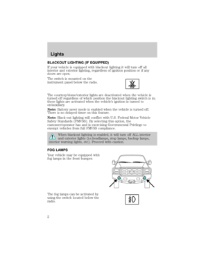
Refer to the label on the front of the sun visors regarding airbag and
seatbelt usage.
This vehicle is not equipped with airbags. Always wear your
seatbelt.
Safety Restraints
17
Page 18 of 28
 DEACTIVATION IN 4WD
(IF EQUIPPED)
Refer to the label on the back of the sun visor mirror regarding Anti-lock
Brake System (ABS) operation.
Your vehicle may be equipped wit")
ANTI-LOCK BRAKE SYSTEM (ABS) DEACTIVATION IN 4WD
(IF EQUIPPED)
Refer to the label on the back of the sun visor mirror regarding Anti-lock
Brake System (ABS) operation.
Your vehicle may be equipped with a feature that deactivates the
Anti-lock Brake System (ABS) when 4WD Low is engaged. The ABS
indicator (
ABS) illuminates, to indicate that ABS is deactivated, and
stays on as long as 4WD Low is engaged.
When 4WD Low is disengaged, the ABS light turns off and the system is
active again.
SUSPENSION UPGRADE PACKAGE
Your vehicle is equipped with a special suspension package that will
enhance the vehicle's off-road performance. The vehicle will handle
differently, both on and off-road, from a factory-equipped passenger car
or truck.
Vehicles with a higher center of gravity such as utility and
four-wheel drive vehicles handle differently than vehicles with a
lower center of gravity. Utility and four-wheel drive vehicles are not
designed for cornering at speeds as high as passenger cars any more
than low-slung sports cars are designed to perform satisfactorily under
off-road conditions. Avoid sharp turns, excessive speed and abrupt
maneuvers in these vehicles. Failure to drive cautiously could result in
an increased risk of loss of vehicle control, vehicle rollover, personal
injury and death.
Dual action remote control suspension
To operate the system:
1. Push the red button to pressurize the system for a firmer ride.
Driving
18
Page 19 of 28

2. Push the black buttons on the bleed valves for a softer ride. Separate
bleed valves allow independent adjustment of front and rear shocks.
Note:Do not operate the compressor for more than 30 seconds at a
time. Allow the compressor to cool down for one minute between
operations.
Note:Stop compressor operation when the arrow on the gauge reaches
maximum. Continuing to supply pressure will not make the shocks any
firmer and damage to the system will occur.
The following table is an example of typical settings for the suspension.
Setting Front Rear
High-speed firm ride 8 6
Slow-speed soft ride 2 2
Towing 5 8
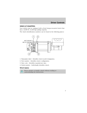
LOCKING REAR DIFFERENTIAL
General information
Your vehicle may be equipped with a locking rear differential; vehicles
equipped with this differential should be identified by a ªCautionº label
mounted on the instrument panel. Vehicle handling characteristcs will be
different than a conventional differential. Examples of this would be:
²When turning a corner, the sound of component disengagement and
re-engagement may be audible, and the transfer of driving torque from
both wheels to one wheel may be noticeable.
²When going from drive (acceleration) to coast (deceleration) in a
turn, a ªmetallicº sound may be heard as torque flow is reversed
(inside wheel engaged during acceleration; outside wheel engaged
during deceleration).
²When negotiating a turn (outside wheel disengaged), the inside wheel
under conditions of poor traction may receive excessive torque, which
could cause it to break traction momentarily until its speed is equal to
the outside wheel. This will result in re-engagement of the outside
wheel thus allowing both wheels to be driven. This condition is most
noticeable with lightly loaded axles.
Driving
19
Page 20 of 28

Use extreme caution when accelerating or decelerating on
slippery or unstable surfaces. Vehicles/axles equipped with
traction differentials are inherently more sensitive to side-slip than
vehicles equipped with conventional differentials. Stability can be
retained if side-slip occurs by decelerating (letting off the accelerator).
Do not apply the brake. To do so may result in loss of vehicle control.
The vehicle's braking capacity is reduced when a turn is made while
coasting downhill because the inside wheel is then disconnected from the
driveline. Operating in low gear will allow the engine to act as a retarder
and will improve braking capacity.
Inspection and lubrication
When servicing any driveline components on a vehicle equipped
with a locking rear differential, ensure that the engine is off and
all wheels are off the ground to prevent the vehicle from moving. Axles
equipped with a locking rear differential deliver power to both wheels,
even when only one wheel is on the ground. Failure to observe these
cautionary measures may cause the vehicle to move which can result
in property damage, personal injury, even death.
This differential is designed to operate in the lubricant recommended by
the vehicle/axle manufacturer; no special lubricant is needed. Refer to
theLubricant Specificationsin yourOwner's Guidefor the proper axle
lubricant. For very cold weather applications, use the lightest oil the axle
manufacturer will allow to overcome possible sluggish reengagement of
the driven clutch assemblies.
No adjustments or alterations should be made to the differential. Refer to
the vehicle/axle manufacturer's instructions for adjustments to other
components in the axle.
SAND INGESTION
When driving through sand, traction or brake capability may be limited.
Also, sand may enter your engine's air intake and severely damage your
engine or your vehicle may stall. Driving through sand where the
transmission vent tube or external breather kit is submerged may allow
sand into the transmission and cause internal transmission damage.
Driving
20
Page 21 of 28

WHEELS
Your vehicle may be equipped with two-piece bolt-together beadlock
rims. Beadlock rims allow the tires to survive operating at lower air
pressure which provide greater traction due to the larger tire-to-ground
contact area during slow, off-road operation. Always reinflate the tires to
the tire manufacturer's recommendations when no longer in slow,
off-road driving conditions. The beadlock also acts as a safety device
ensuring that the tire does not unseat from the rim or rotate on the
wheel when tire pressure is reduced, while also preventing the entry of
foreign objects, debris or water into the tire's air chamber.
Note:The wheel/tire assemblies should be serviced only by trained
personnel who have read and understand the wheel
assembly/disassembly information contained within theWorkshop
Manual.
TIRES
Each tire is equipped with a Variable Function Insert (VFI) which is
mounted into the tire. The VFI insert and tire are then fitted around the
beadlock rim assembly, providing a higher level of tire protection due to
the dense rubber material in the tire assembly and maximum all-terrain
mobility.
SNOW CHAINS
Tire chains cannot be used on vehicles equipped with M/TR tires.
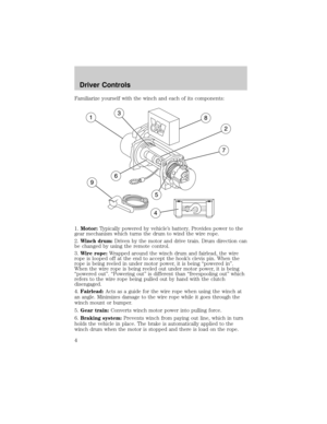
ON-BOARD AIR SYSTEM (IF EQUIPPED)
Your vehicle may be equipped with an on-board air system which has
been designed to provide compressed air for multiple uses, including the
addition of air to the vehicle's tires. The system uses a 25 ft. (7.6m)
length of air hose equipped with a clamp-on style air chuck. When not in
use, this hose is secured to the floor of the truck. A compressor,
mounted to the frame under the truck on the passenger side frame rail,
is included along with an air reservoir on the driver side. When the
compressor is on, the output pressure at the air tank is limited to 80 psi
(552 kPa).
Tires, Wheels and Loading
21
Page 22 of 28

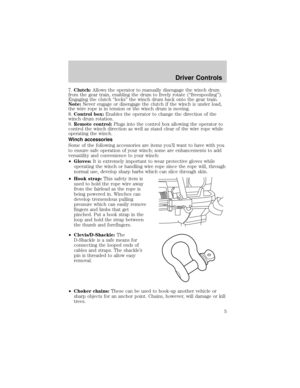
The air coupling, to which the hose
is to be connected, is located just
above the floor behind the driver's
seat.
The compressor is controlled by an
instrument panel mounted switch
below the radio. The compressor
cannot be turned on unless the
vehicle ignition is in the ON position
Note:The air compressor uses significant electrical current when
operating. It is recommended that the engine be running when the
compressor is in use to avoid discharging the battery.
When the compressor is switched to the on position, a light in the switch
will be illuminated and the reservoir pressure will increase until it
reaches the pre-set limit. The light will remain on even when the pre-set
pressure limit is reached and the compressor turns off. With the switch
turned on, the compressor may start at any time the ignition switch is in
the ON position. You should turn the compressor switch off until you
plan on using compressed air to avoid possible injuries and minimize
wear on the compressor and system.
Note:When the system is pressurized, all air lines from the compressor
to the outlet chuck are pressurized as well. Do not attempt to work on
the system or loosen any fittings unless you have drained all pressure
from the system by opening the drain on the air reservoir.
Whenever the air compressor has been used, be sure to drain the air
system of all pressure by opening the drain valve at the front of the
reservoir until air no longer escapes.Do not leave the system
pressurized when the vehicle is not in use.This will help to assure
the safety of those who may need to work on the truck and prevent the
condensation of water in the reservoir, extending the life of air system
components.
The air compressor inlet is equipped with a filter to prevent the
ingestion of contamination into the compressor and air system. This filter
Tires, Wheels and Loading
22
Page 23 of 28

is located underneath the truck, by the forward stake pocket on the left
side of the bed. If operating the air system in dusty areas, periodically
inspect this filter and replace it if found to be clogged or damaged, or if
the time needed to pressurize the system starts to become extended.
Using the air system to fill tires
To fill your tires, first be sure to stop the truck in a safe place. You
should be far enough off the road that passing traffic will not be a danger
to you. You should have an accurate tire pressure gauge to measure the
pressure in the tires and inflate them to the settings on the tire pressure
placard, which is usually inside the door on the truck.
Remove the air hose from under the clamp on the floor of the truck.
Attach the connector end of the hose to the coupling in the trim panel
behind the driver's seat by using one hand to slide the coupling collar
toward the trim panel and the other to insert the fitting on the end of
the hose into the coupling. When the fitting is seated in the coupling,
slide the collar back to its original position.
Extend the hose to reach the tire needing air. Remove the cap from the
tire valve stem and attach the clamp-on air chuck by squeezing the
locking mechanism while placing the chuck over the valve stem. Release
the locking mechanism when the air chuck is seated on the stem. Air will
flow from the system to the tire until you remove the chuck. Be sure to
use your gauge to set the pressure according to the placard. When the
tire pressure is correct, disconnect the hose and re-stow it under the
clamp on the floor behind the passenger seat. Do not forget to re-install
the cap on the valve stem.
CENTRAL TIRE INFLATION SYSTEM (CTIS) (IF EQUIPPED)
Your vehicle may be equipped with a
Central Tire Inflation System
(CTIS). The CTIS adjusts and
maintains tire pressure for enhanced
vehicle traction, reduced vehicle
maintenance and improved driver
comfort. The system is operated
through instrument panel-mounted
controls.
Operating the CTIS
The CTIS is operated and observed through the Driver Display Module
(DDM) and the LOAD AND TERRAIN controls.
Tires, Wheels and Loading
23
Page 24 of 28
 for operation on
improved surfaces
²CC (Cross Country) for operation
on secondary roads
²SS (Sand) for operation on san")
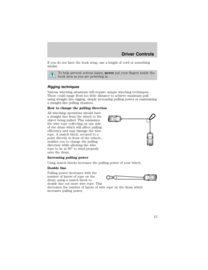
DDM
Displays current CTIS status and
alerts.
1.TERRAIN display:
²HY (Highway) for operation on
improved surfaces
²CC (Cross Country) for operation
on secondary roads
²SS (Sand) for operation on sand,
trails and unimproved surfaces
²E (Emergency) for selection of extremely low tire pressures to help
free stuck vehicle or to traverse bad terrain
Dashes displayed in DDM Terrain display
²CTIS system fault
²CTIS has shut off at least one channel due to fault tolerance
²System may periodically check to see if fault still exists
²Operation may be allowed on unaffected channels
²Check tires for proper pressure and get service at earliest opportunity
2.LOAD bar graph display:
²Off: Unloaded
²On: Loaded
3.Channel display:
²FRT: Front axle
²RR: Rear axle
When the terrain channel is flashing, the CTIS is working to achieve
pressures that are appropriate with the indicated terrain or checking
pressure.
When the terrain channel is solid, the tires are at the appropriate
pressure, the CTIS is in maintenance mode and the wheel valves are
closed.
4.OVERSPEED
²Flashing or buzzer activated:Vehicle speed has exceeded the
programmed speed limit for the current tire pressure.
Tires, Wheels and Loading
24