2007 FORD FIESTA break
[x] Cancel search: breakPage 21 of 1226

100-00-5 General Information 100-00-5
DESCRIPTION AND OPERATION
Component Tests
' A component test is used when a component is
tested in multiple pinpoint tests, or if a procedure
is too complicated to be formatted within a single
page of the pinpoint test.
Graphics
Test graphics show the measurement or test to be
performed in a test step.
A representative tester graphic is used for
voltmeters and ohmmeters.
If multiple measurements are made in a single
graphic, the test leads are drawn with a solid line
until the test lead splits to indicate the multiple
measurements, at which point dashed lines are
used.
Breakout box-type testers are represented by a
double circle test pin. Test pins are labeled with
the pin number.
Special Tools and Torque Figures
Any requirement for special tools will picture the
tool, showing it in use and with its tool number
( ' shown. Torque settings will be given at the relevant
point in the procedure.
2006.0 Fiesta 1212006 GI 7371 en
procarmanuals.com
Page 25 of 1226

100-00-9 General Information 100-00-9
DESCRIPTION AND OPERATION
Chemical Materials - Do's
/ I - Do carefully read and observe hazard and
precaution warnings given on material
containers (labels) and in any accompanying
leaflets, posters or other instructions. Material
health and safety data sheets can be obtained
from manufacturers.
- Do remove chemical materials from the skin
and clothing as soon as practicable after soiling.
Change heavily soiled clothing and have it
cleaned.
- Do organize work practices and protective
clothing to avoid soiling of the skin and eyes;
breathing vapors, aerosols, dusts or fumes;
inadequate container labeling; fire and explosion
hazards.
- Do wash before job breaks, before eating,
smoking, drinking or using toilet facilities when
handling chemical materials.
- Do keep work areas clean, uncluttered and free
of spills.
- Do store chemical materials according to
national and local regulations.
- Do keep chemical materials out of the reach of
( ' children.
- Do not clean hands or clothing with chemicals.
Chemicals, particularly solvents and fuels, will
dry the skin and may cause irritation leading to
dermatitis or be absorbed through the skin in
toxic or harmful quantities.
- Do not use emptied containers for other
materials except when they have been cleaned
under supervised conditions.
- Do not sniff or smell chemical materials. Brief
exposure to high concentrations of fumes can
be toxic or harmful.
Chlorofluorocarbons (CFC)
There is concern in the scientific community that
CFCs and Halons are depleting the upper ozone
layer which filters out harmful ultraviolet radiation.
Decreased filtration of ultraviolet radiation may
result in increases in skin cancer, cataracts and
immune system suppression in humans, as well
as decreased productivity of crops and aquatic
systems.
CFCs are used primarily as refrigerants in vehicle
air conditioning systems and as aerosol
propellants. Halons are used as fire extinguishants.
Clutch Fluids
Chemical Materials - Do Nots
See Brake fluids.
- Do not mix chemical materials except under the
manufacturers instructions; some chemicals can
form other toxic or harmful chemicals, give off
toxic or harmful fumes or become explosive
when mixed together.
- Do not spray chemical materials, particularly
those based on solvents, in confined spaces,
for example when people are inside a vehicle.
- Do not apply heat or flame to chemical materials
except under the manufacturers instructions. Some are highly flammable and some may
release toxic or harmful fumes.
- Do not leave containers open. Fumes given off
can build up to toxic, harmful or explosive
concentrations. Some fumes are heavier than
air and will accumulate in confined areas such
as pits.
- Do not transfer chemical materials to unlabelled
containers.
Clutch Linings and Pads
See Asbestos.
Corrosion Protection Materials
See also Solvents, Fire.
Highly flammable, flammable
- observe No
Smoking policy.
These materials are varied and the manufacturers instructions must be followed. They may contain
solvents, resins or petroleum products. Skin and
eye contact should be avoided. They should only be sprayed in conditions of adequate ventilation
and not in confined spaces.
Cutting
See Welding.
2006.0 Fiesta 1212006 GI 7372en
procarmanuals.com
Page 1004 of 1226
Automatic Transmission/Transaxle -
Vehicles With: 4-Speed Automatic
307-01
-44 Transmission (AW81-40) 307-01 -44
DESCRIPTION AND OPERATION
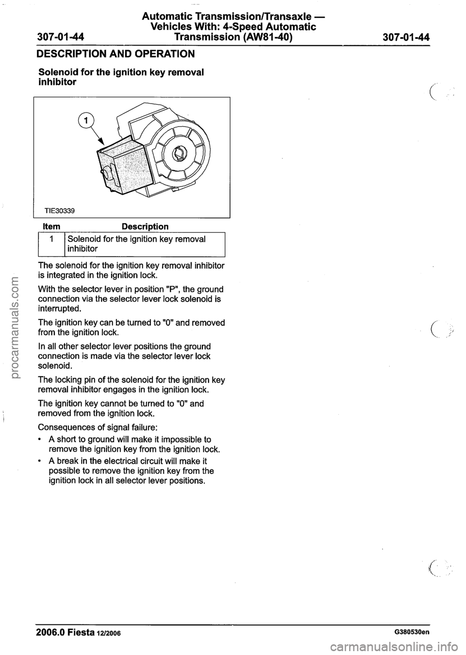
Solenoid for the ignition key removal
inhibitor
Solenoid for the ignition key removal
inhibitor
The solenoid for the ignition key removal inhibitor
is integrated in the ignition lock.
With the selector lever in position
"P", the ground
connection via the selector lever lock solenoid is
interrupted.
The ignition key can be turned to
"0" and removed
from the ignition lock.
In all other selector lever positions the ground
connection is made via the selector lever lock
solenoid.
The locking pin of the solenoid for the ignition key
removal inhibitor engages in the ignition lock.
The ignition key cannot be turned to
"0" and
removed from the ignition lock.
Consequences of signal failure:
A short to ground will make it impossible to
remove the ignition key from the ignition lock.
A break in the electrical circuit will make it
possible to remove the ignition key from the
ignition lock in all selector lever positions.
2006.0 Fiesta 12/2006 G380530en
procarmanuals.com
Page 1218 of 1226

Acceleration Control - 1.3L Duratec-8V
(Rocam)llI25L Duratec-1 6V (Sigma)llI4L
31 0-02A-4 Duratec-1 6V (Sigma)/l .6L
Duratec-1 6V (Sigma)
31 0-02A-4
DIAGNOSIS AND TESTING
Electronic Throttle Body
The electronic throttle body is similar to a
mechanical throttle body used on a cable
accelerator system. Instead of the cable moving
the throttle plate open and closed, it uses an
internal electrical motor that is driven by the PCM.
The electronic throttle body has two sensors that
measure the throttle plate position. The sensors
output a voltage to the PCM corresponding to the
plate position.
When the electronic throttle body motor is not in
use, the throttle plate sits slightly open in a default
position (not idle position). This position is
maintained by two internal springs. One acts
upwards and one downwards. Screws on the
electronic throttle body will not adjust the idle
speed, the idle speed is controlled by the PCM.
PCM
The PCM reads the voltage from the pedal and
converts this signal into a driver request. The driver
request is realized by opening or closing the throttle
body. To do this, the PCM increases or decreases
power to the electronic throttle body motor. The
PCM then checks the signal from the electronic
throttle body throttle position (TP) sensor, to make
sure that the requested position has been
achieved. The PCM also monitors all the sensors
to make sure that the system is functioning as
expected. All electronic accelerator control system
faults will be detected by the PCM and set a
diagnostic trouble code (DTC) which triggers the
electronic accelerator control fail message
accordingly. For safety reasons, some faults will
also reduce the vehicle performance.
Diagnostic Trouble Codes
Description
When a component electrical error is set it means
that the PCM is not receiving the expected signal.
This means that the concern may lie between the
component and the PCM. All wiring and electrical
connectors should be checked before a new
component is installed. Also note that general
vehicle electrical issues can have an effect on other
systems. Battery voltage and relay concerns should
be rectified first.
Accelerator Pedal Codes
These are the DTCs relating to the pedal circuit.
They do not imply necessarily that the accelerator
pedal is at fault, but it will in any case relate to area
"A (see system overview).
P2120 - Accelerator pedal sensor 1 electrical
error
P2122 - Accelerator pedal sensor I electrical
error short to ground or open circuit
P2123 - Accelerator pedal sensor I electrical
error short to battery
P2125 - Accelerator pedal sensor 2 electrical
error
P2127 - Accelerator pedal sensor 2 electrical
error short to ground or open circuit
P2128 - Accelerator pedal sensor 2 electrical
error short to battery
P2138 - Accelerator pedal sensor 1 & 2 ratio
error
Electronic Throttle Body Circuit Codes
These are the DTCs relating to the electronic
throttle body circuit. They do not imply necessarily
( ,)
that the electronic throttle body is the concern, but
it will in any case relate to area "B" (see system
overview).
PO1 20 - Throttle position (TP) sensor 1
electrical error
PO122 - (TP) sensor 1 electrical error short to
ground
PO123 - (TP) sensor 1 electrical error short to
battery or line break
PO220 - (TP) sensor 2 electrical error
PO222 - (TP) sensor 2 electrical error short to
ground or open circuit
PO223 - (TP) sensor 2 electrical error short to
battery
P2135 - (TP) sensor ratio error
P21
I 9 - Throttle plate convergence error
- This is when the throttle plate has not moved
to the requested position in the required time.
This could be caused by the following:
- The electronic throttle body motor is not
receiving the necessary voltage. Check the
--
electronic throttle body motor wiring. The ( PCM is not receiving the correct throttle plate '
position signal from the electronic throttle
body. Check the TP sensor wiring from the
2006.0 Fiesta 1212006 G356253en
procarmanuals.com