2007 FORD FIESTA brakes
[x] Cancel search: brakesPage 961 of 1226

Automatic Transmission/Transaxle .
Vehicles With: 4-Speed Automatic
Transmission
(AW81-40)
SECTION 307-01 Automatic Transmission/Transaxle
. Vehicles With: 4-Speed Automatic Transmission
(AW81-40)
VEHICLE APPLICATION:2006.0 Fiesta
CONTENTS PAGE
SPECIFICATIONS
Specifications
........................................................................\
.............................................. 307-0 1 -3
DESCRIPTION AND OPERATION
Automatic Transaxle
........................................................................\
...................................
Transmission cross-section ........................................................................\
........................
Torque converter with Torque Converter Clutch (TCC) ......................................................
Fluid pump and stator shaft ........................................................................\
........................
........................................................................\
......... Planetary gearset ......................... .:
Clutches and brakes ........................................................................\
...................................
Intermediate gear stage and differential assembly .............................................................
Main control body ........................................................................\
.......................................
Internal' gearshift mechanism ........................................................................\
.....................
Fluid circuit ........................................................................\
.................................................
........................................................................\
....................................... Identification Tags
Type plate
........................................................................\
...................................................
Transmission Ranges and Power Flow ........................................................................\
......
Transmission ratio and power flow route - 1st gear ............................................................
Transmission ratio and power flow route - 2nd gear ..........................................................
Transmission ratio and power flow route . 3rd gear ...........................................................
Transmission ratio and power flow route . 4th gear ...........................................................
Transmission ratio and power flow route . reverse gear ....................................................
Transaxle Electronic Control System ........................................................................\
..........
........................................................................\
..................................................... Overview
Transmission control unit
........................................................................\
............................
........................................................................\
.................................... Gearshift strategies
Selector lever positions
........................................................................\
..............................
Signal transmission on the CAN databus ........................................................................\
...
........................................................................\
...................................................... Sensors
........................................................................\
.................................................... Actuators
DIAGNOSIS AND TESTING
Automatic Transaxle
........................................................................\
................................... 307-01
Inspection and Verification ........................................................................\
.................... 307-01
Diagnostic Trouble Code Chart
........................................................................\
.................. 307-01
........................................................................\
...................................... Line Pressure Test 307-01
Stall Speed Test
........................................................................\
....................................... 307-01
Time Lag Test
........................................................................\
............................................. 307-01
procarmanuals.com
Page 968 of 1226

Automatic Transmission/Transaxle -
Vehicles With: 4-Speed Automatic
Transmission
(AW81-40) 307-01 -8
DESCRIPTION AND OPERATION
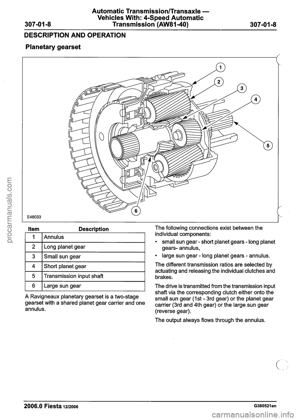
Planetary
gearset
Description The following connections exist between the
/ individual components:
small sun gear - short planet gears - long planet
Long planet gear gears- annulus,
3 Small sun gear large sun gear - long planet gears - annulus.
4
5
The output always flows through the annulus.
6
2006.0 Fiesta 1212006 ~380521 en
Short planet gear
Transmission input shaft The different transmission ratios
are selected by
actuating and releasing the individual clutches and
brakes.
shaft via the corresponding clutch either onto the
A Ravigneaux planetary gearset is a two-stage
small sun gear (1st - 3rd gear) or the planet gear gearset with a shared planet gear carrier and one carrier (3rd and 4th gear) or the large sun gear annulus. (reverse gear).
Large sun gear
The drive is transmitted from the transmission input
procarmanuals.com
Page 969 of 1226

Automatic Transmission/Transaxle -
Vehicles With: 4-Speed Automatic
Transmission
(AW81-40)
DESCRIPTION AND OPERATION
Clutches and brakes
/
Description The clutches are multi-plate clutches.
I 1 I I st - 3rd gear clutch I
1 2 14th gear brake I
1 3 1 Reverse gear clutch I
1 4 12nd - 4th gear brake I
1 6 1 3rdl4th gear clutch I
1 7 1 1st gear one-way clutch I
1 8 12nd gear one-way clutch I
The transmission is equipped with three clutches
and five brakes. The brakes
are three multi-plate brakes and two
one-way sprag clutches.
The clutches serve to transmit the torque from the
transmission input
shaft to certain components of
the planetary
gearset.
The brakes serve to hold certain components of
the planetary
gearset.
In order to achieve a given transmission ratio, it is
necessary for at least one component of the
planetary
gearset to be held while the torque is
transmitted to another component.
These combinations produce the different
transmission ratios for the individual gears.
2006.0 Fiesta 1212006 G380521 en
procarmanuals.com
Page 972 of 1226

Automatic Transmission/Transaxle -
Vehicles With: 4-Speed Automatic
307-01 -1 2 Transmission (AW81-40) 307-01 -1 2 --
DESCRIPTION AND OPERATION
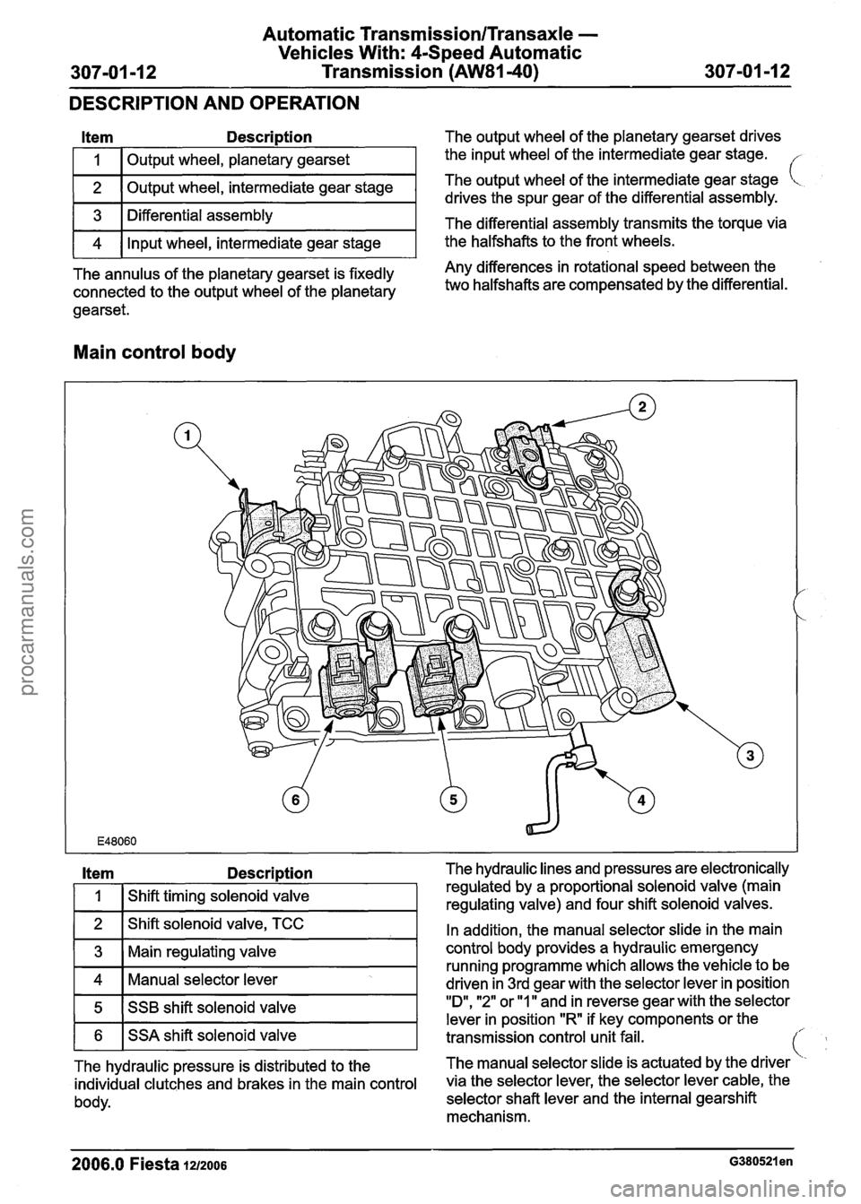
Item Description The output wheel of the planetary gearset drives
I 1 I Output wheel, planetary gearset
2
I I 1
The annulus of the planetary gearset is fixedly Any differences in rotational speed between the
connected to the output
wheel of the planetary two halfshafts are compensated by the differential.
gearset.
the input wheel of the intermediate gear stage.
3
4
Main control body
Output wheel, intermediate gear stage
Item Descri~tion The hydraulic lines and pressures are electronically
The output
wheel of
the intermediate gear stage [<.
drives the spur gear of the differential assembly.
Differential assembly
Input wheel, intermediate gear stage The
differential assembly transmits the torque
via
the halfshafts to the front wheels.
In addition, the manual selector slide in the main
control body provides a hydraulic emergency
running programme which
allows the vehicle to be
Manual selector lever driven in 3rd aear with the selector lever in position
.
1
Shift timing solenoid valve
5
2006.0 Fiesta 1212006 ~380521 en
regulated by a proportional solenoid valve (main
regulating valve) and four shift solenoid valves.
1 6 1 SSA shift solenoid valve
SSB
shift solenoid valve
transmission control unit-fail. -
"D", "2" or "ll'and in reverse gear with the selector
lever in position "R if key components or the
The hydraulic pressure is distributed to the The
manual selector slide is actuated by the driver
individual clutches and brakes in the main control via the selector lever, the selector lever cable, the
body. selector shaft lever and the internal gearshift
mechanism.
procarmanuals.com
Page 974 of 1226

Automatic Transmission/Transaxle -
Vehicles With: 4-Speed Automatic
Transmission
(AW81-40)
DESCRIPTION AND OPERATION
Fluid circuit
Item Description
I 1 I Transmission control unit
1 2 1 Solenoid valves and main control body I
1 3 I Clutches and brakes I
1 4 1 Planetary gearset
1 5 1 Fluid pump I
1 6 1Oil pan I
1 7 1 Fluid cooler I
Item Description
1 8 I Torque converter I
I A I Electric actuation of the solenoid valves I
B Actuating pressure of the clutches and
1 lbrakes
I C ITo the oil pan I
I D I From the oil pan I
I E I Fluid pump pressure I
2006.0 Fiesta 121~006 ~380521 en
procarmanuals.com
Page 992 of 1226

Automatic Transmission/Transaxle -
Vehicles With: 4-Speed Automatic
307-01 -32 Transmission
(AW81-40) 307-01 -32
DESCRIPTION AND OPERATION
This is influenced by the following variables:
Engine speed,
Engine load,
Transmission input speed,
Vehicle speed.
The following are actuated:
PCM (torque reduction request signal via the
CAN databus).
Pressure control during gearshifts
In order to ensure that the engagement of the
clutches and brakes is as judder-free as possible,
the main line pressure is reduced during gearshifts.
This is influenced by the following variables:
Enginespeed,
Engine load,
Transmission input speed,
Vehicle speed.
The following are actuated:
Main regulating valve.
Shift timing adaptation during upshifts
In order to ensure that the engagement of the
clutches and brakes is as judder-free as possible,
the timing of the gearshift processes is monitored
during upshifts.
In the event of any discrepancy from the target
values, the main line pressure is adapted
accordingly during the next gearshift.
The shift timing adaptation during upshifts is only
active at transmission fluid temperatures between
50
"C and 120 "C.
This is influenced by the following variables:
Engine load,
Accelerator pedal position,
Transmission input speed,
Vehicle speed,
Transmission fluid temperature,
Selector lever position.
The following are actuated:
Main regulating valve.
Shift timing adaptation during shifts from
3rd to 4th gear
The shift from 3rd gear into 4th gear is the only
gearshift during which a clutch is disengaged and
a brake is engaged simultaneously.
In order to control the synchronized switching of
the two components as exactly as possible, the
shifl timing solenoid valve is actuated accordingly.
In order to ensure that this particular gearshift is
performed as judder-free as possible throughout
the service life of the transmission, the gearshift is
monitored by the two rotational speed sensors and
the actuation of the shift timing solenoid valve is
adapted accordingly.
The shift timing adaptation for gearshifts from 3rd
gear into 4th gear is only active at transmission
fluid temperatures between 30
"C and 120 "C.
This is influenced by the following variables:
Engine load,
Accelerator pedal position,
Transmission input speed,
Vehicle speed,
Transmission fluid temperature,
Selector lever position.
The following are actuated:
Shift timing solenoid valve.
Shift timing adaptation during shifts from
4th to 3rd gear
The shift from 4th gear into 3rd gear is the only
gearshift during which a brake is disengaged and
a clutch is engaged simultaneously.
In order to control the engagement of the clutch as
precisely as possible, the main regulating valve is
actuated accordingly in order to build up the
actuating pressure at exactly the right time.
In order to ensure that this particular gearshift is
performed as judder-free as possible throughout
the service life of the transmission, the gearshift is
monitored by the two rotational speed sensors and
the actuation of the main regulating valve is
adapted accordingly.
The shift timing adaptation for gearshifts from 4th
-
gear into 3rd gear is only active at transmission (
fluid temperatures between 20 "C and 120 "C. .
2006.0 Fiesta 1212006 G380530en
procarmanuals.com
Page 1000 of 1226

Automatic Transmission/Transaxle -
Vehicles With: 4-Speed Automatic
307-01 -40 Transmission (AW81-40)
307-01 -40
DESCRIPTION AND
OPEMION
Driver's side door ajar switch
The door ajar switch is located in the door lock on
the driver's side.
When the door is closed a ground connection is
signalled to the transmission control unit.
When the door is opened this ground connection
is interrupted.
The transmission control unit uses the signal from
the driver's side door ajar switch to warn the driver
if the selector lever is not in position
"P" and the
driver's door is open.
In this case the transmission control unit transmits
the warning tone request via the CAN
databus to
the instrument cluster.
The instrument cluster passes this request on to
the GEM, which then generates a warning tone.
Consequences of signal failure:
no warning tone request.
Actuators
Main regulating valve
Item Description
I 1 I Main regulating valve I
The main regulating valve is a proportional valve
which converts the applied electric current into a
proportional hydraulic pressure.
The currentless state corresponds to maximum
pressure.
/
The main regulating valve is used to determine the
main line pressure and therefore the actuating
pressure for the clutches and brakes.
Consequences of signal failure:
hydraulic emergency running mode.
SSA and SSB shift solenoid valves
Item Description
2006.0 Fiesta 1212006 G380530en
1
2
SSA
SSB
(- t..
procarmanuals.com