Page 796 of 1226

303-03B-26 Engine Cooling - 2.OL Duratec-HE (M14) 303-03B-26
REMOVAL AND INSTALLATION
Removal 2. Push the cooling fan motor and shroud l.
upwards and then downwards to remove.
1. Disconnect the battery ground cable. I
For additional information, refer to: Battery
Disconnect
(414-01 Battery, Mounting and
Cables, General Procedures).
2. Drain the cooling system.
For additional information, refer to: Cooling
System Draining, Filling and Bleeding
(303-03 Engine Cooling - 2.OL Duratec-HE
(M14), General Procedures).
3. Disconnect the cooling fan motor and
cooling fan resistor electrical connectors.
4. Remove
the air cleaner intake pipe resonator.
5. Remove the cooling fan motor and shroud.
1. Release the cooling fan motor and shroud
from the retaining brackets.
6. Disconnect the radiator upper hose.
1. Pull out the quick release spring clip.
2. Pull the radiator upper hose from the quick
release connector.
7. Disconnect the radiator degas hose from the
radiator.
Release the locking tangs.
8. Remove the radiator retainers.
2006.0 Fiesta 1212006 G457934en
procarmanuals.com
Page 797 of 1226
303-03B-27 Engine Cooling - 2.OL Duratec-HE (M14) 303-03B-27
REMOVAL AND INSTALLATION
I. Remove the radiator retainer locking screws.
2. Remove the radiator retainers and grommets.
9. Detach the radiator and the air conditioning
(NC) condenser from the support panel.
Om ACAUTION:S~~~~~~ the AIC condenser
by positioning it on the support panel.
Slide the
NC condenser to detach it from the
radiator
, 11. Remove the radiator. I
Installation
I. To install, reverse the removal procedure.
2006.0 Fiesta 1212006 G457934en
procarmanuals.com
Page 814 of 1226

Fuel Charging and Controls - 2.OL
303-04B-6 Duratec-HE (M14) 303-04B-6
DIAGNOSIS AND TESTING
1 6 1 Heated Oxygen sensor (H02s) I
Item Description Fuel supply
1 7 1 Intake manifold I
5
Fuel injectors
Throttle body
The fuel supply for all petrol fueled variants is
equipped with a return-less fuel system. This
means that the fuel delivery pressure at the fuel
injectors, is monitored and controlled by the fuel
tank module. This control is achived by switching
the fuel pump on and off.
The fuel pump module for both the Ethanol E85
TO maintain the same or similar power output to variant vehicle and the unleaded fueled vehicle are
that of the unleaded fuel vehicle, the fuel injectors
very similar, visual^ the only difference is the fuel
have been replaced with high flow fuel injectors. pump electrical connections which on the Ethanol
E85 variant is sealed. This is not the only
differance, both fuel pump modules have different
(
Fuel composition monitoring fuel level sensor resistor card values.
The quantity of Ethanol E85 in relation to the
quantity of unleaded fuel contained in the fuel tank
at any one time is not monitored at the fuel tank.
The Ethanol percentage volume can only decrease
from its maximum 85% (pure Ethanol
E85), to zero
(1 00% unleaded fuel).
The fuel charging system compensates for the
changes in fuel composition using the signal
received by the power train control module (PCM)
from the
H02s. The PCM adapts the fueling and
ignition calibrations to suit the current fuel tank
content composition.
Cold start
To overcome the problems relating to cold start
inherent with Ethanol E85 vehicles (temperatures
down to -29 degrees centigrade), a block heater
has been installed into the engine coolant system.
The block heater is located to the rear of the engine
under the exhaust manifold. The block heater is
fitted with a dedicated harness which terminates at an external plug connector fitted into the radiator
grill.
2006.0 Fiesta 1212006
procarmanuals.com
Page 902 of 1226
Engine Emission Control - 2.OL Duratec-HE
(MI41
REMOVAL AND INSTALLATION
Exhaust Gas Recirculation (EGR) Valve
1. Drain the cooling system.
For additional information, refer to: Cooling
Special
Tool(s) 3.
Remove the air cleaner intake tube.
System Draining, Filling and Bleeding
24003
(303-03 Engine cooling - 2.01 Duratec-HE
(M14), General Procedures).
4. Using the special tool, disconnect the
2. Remove the air cleaner outlet pipe.
radiator upper coolant hose from the coolant
outlet connector.
Removerllnstaller, Coolant
Hose Clamp
303-397
5. Remove the components in the order
indicated in the following
illustration(s) and
table(s).
2006.0 Fiesta 1212006 G421887en
procarmanuals.com
Page 906 of 1226
303-1 2-2 Intake Air Distribution and Filtering 303-1 2-2
SPECIFICATIONS
Toraue S~ecifications
1 1.4L Duratorq-TDCi (DV) diesel engine I I I I
Description
Air cleaner intake pipe retaining bolt
- vehicles with
Air cleaner retaining screws
- vehicles with 1.4L
Duratorq-TDCi (DV) diesel engine
Air cleaner outlet hose retaining clip
- vehicles with
1.6L Duratorq-TDCi (DV) diesel engine
Nm
4
Air cleaner intake pipe duct retaining bolts - vehicles
with
I .6L Duratorq-TDCi (DV) diesel engine
Charge air cooler hose retaining clamps
- 1.6L
Duratorq-TDCi (DV) diesel engine
I b-ft
-
Charge air cooler retaining bolts - 1.6L Duratorq-
TDCi (DV) diesel engine
I b-in
35
Radiator support bracket retaining bolts - 1.6L
Duratorq-TDCi (DV) diesel engine
2006.0 Fiesta 1212006 G148224en
procarmanuals.com
Page 1039 of 1226

Transmission/Transaxle Cooling - Vehicles
With: 4-Speed Automatic Transmission
307-0213 (AW81-40) 307-02-3
DESCRIPTION AND OPERATION
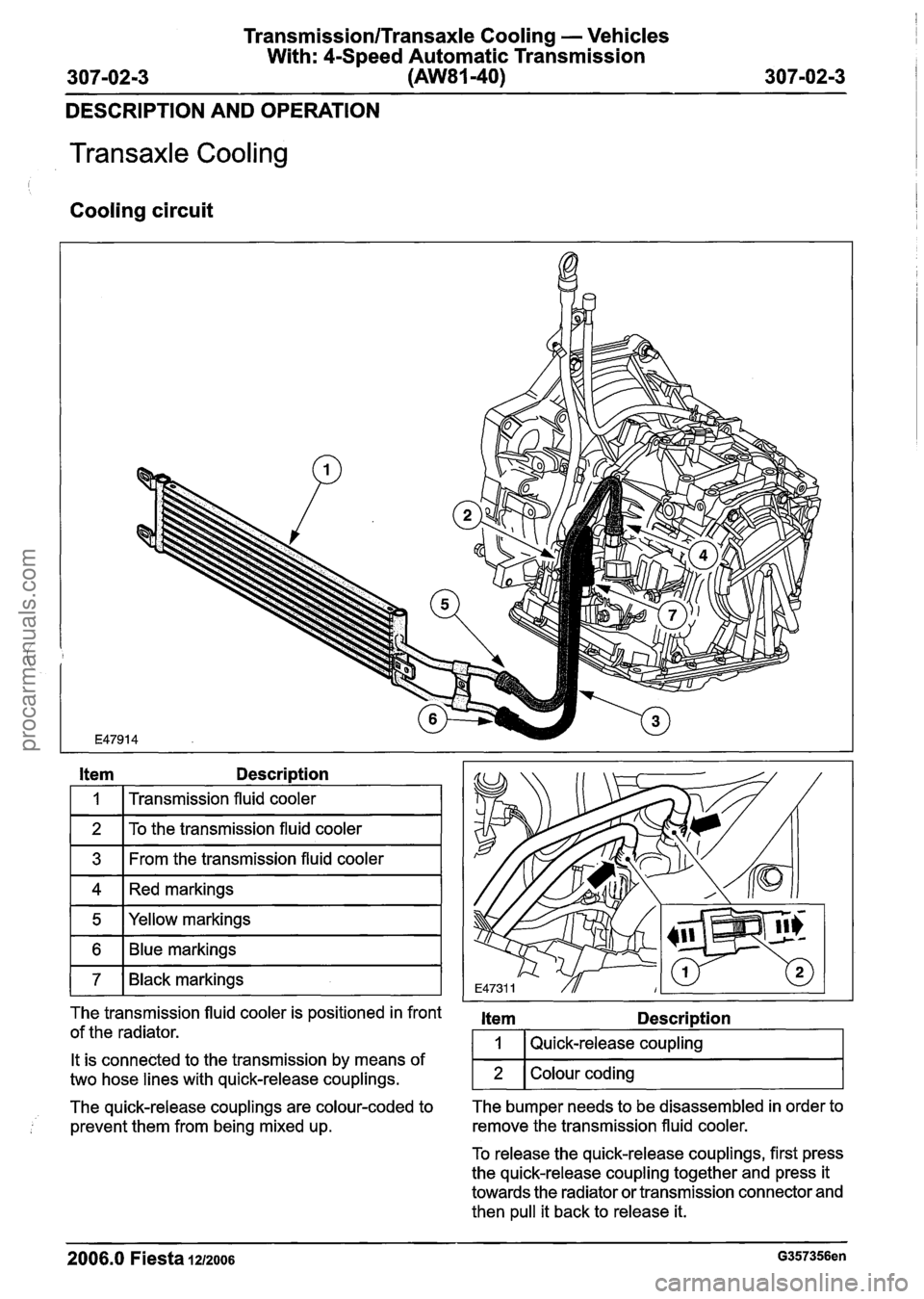
Transaxle Cooling
Cooling circuit
I I
Item Description
I 1 I Transmission fluid cooler I
11 To the transmission fluid cooler I
1 3 1 From the transmission fluid cooler I
ml~ed markings I
1 5 I Yellow markings I
1 7 1 Black markings I
The transmission fluid cooler is positioned in front item Description
of the radiator. I 1 I Quick-release coupling
The quick-release couplings are colour-coded to The
bumper needs to be disassembled in order to
prevent them from being mixed up. remove
the transmission fluid cooler.
It is
connected to the transmission by means of
two hose lines with quick-release couplings.
To release the quick-release couplings, first press
the quick-release coupling together and press it
towards the radiator or transmission connector and
then pull it back to release it.
2006.0 Fiesta IZIZOO~ G357356en
2
. -
Colour coding
procarmanuals.com
Page 1040 of 1226

TransmissionlTransaxle Cooling - Vehicles
With: 4-Speed Automatic Transmission
307-0214 (AW81-40) 307-02-4
REMOVAL AND INSTALLATION
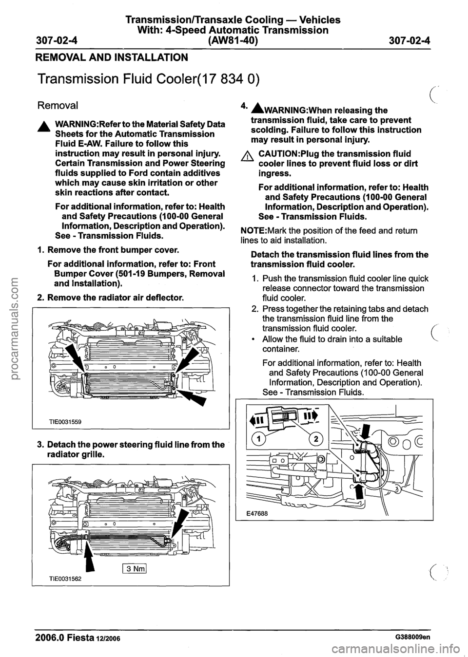
Transmission Fluid Cooler(l7 834 0)
Removal
A WARN1NG:Refer to the Material Safety Data
Sheets for the Automatic Transmission
Fluid E-AW. Failure to follow this
instruction. may result in personal injury.
Certain Transmission and Power Steering
fluids supplied to Ford contain additives
which may cause skin irritation or other
skin reactions after contact.
For additional information, refer to: Health
and Safety Precautions (1 00-00 General
4m AWARNING:~~~~ releasing the
transmission fluid, take care to prevent
scolding. Failure to follow this instruction
may result in personal injury.
A CAUTI0N:PIug the transmission fluid
cooler lines to prevent fluid loss or dirt
ingress.
For additional information, refer to: Health
and Safety Precautions (1 00-00 General
Information, Description and Operation).
See
- Transmission Fluids.
Information, and Operation)' NOTE:Mark the position of the feed and return See - Transmission Fluids. lines to aid installation.
1. Remove the front bumper cover.
Detach the transmission fluid lines from the
For additional information, refer to: Front
transmission fluid cooler.
Bumper Cover (501-19 Removal 1. Push the transmission fluid cooler line quick and Installation). release connector toward the transmission
2. Remove the radiator air deflector. fluid cooler.
3. Detach the power steering fluid line from the
radiator grille.
2. Press together the retaining tabs and detach
the transmission fluid line from the
transmission fluid cooler.
Allow the fluid to drain into a suitable
container.
For additional information, refer to: Health
and Safety Precautions
(1 00-00 General
Information, Description and Operation).
See
- Transmission Fluids.
2006.0 Fiesta 1~12006 G388009en
procarmanuals.com