Page 944 of 1226

303-1 4-20 Electronic Engine Controls 303-1 4-20
DIAGNOSIS AND TESTING
1 PO643 1 Transmission sensor power supply 1 high voltage I
MIL Code
PO641
PO642
1 PO646 1 Air conditioning (NC) clutch relay circuit low voltage I
1 PO647 1 NC clutch relay circuit high voltage I
Description
Transmission sensor power supply 1 noisy signal
Transmission sensor power supply
I low voltage
I PO651 I Transmission sensor power supply 2 noisy signal I
i
PO652
PO653
Transmission sensor power supply 2 low voltage
Transmission sensor power supply
2 high voltage
PO654
PO686
1 PO692 1 Cooling fan 1 control circuit high voltage I
Engine run output circuit malfunction
Main relay malfunction low voltage
PO687
PO691
1 PO693 1 Cooling fan 2 control circuit low voltage I
Main relay malfunction high voltage
Cooling fan
1 control circuit low voltage
1 PO694 1 Cooling fan 2 control circuit high voltage I
I PI500 I Vehicle speed sensor (VSS) output circuit malfunction I
PO704
PI 000
Generator command malfunction I
Clutch switch implausible signal
EOBD system readiness test not complete
I P2107 I Safety failure level 3 I
PI 794
P2100
I P2108 I Safety failure level 2 error I
Battery voltage malfunction too high or too low
Engine throttle body H-bridge malfunction
APP sensor circuit 1 high input I
P2119
P2122
1 P2127 1 APP sensor circuit 2 low input I
Engine throttle body throttle flap malfunction
Accelerator pedal position (APP) sensor circuit
1 low input
1 P2128 1 APP sensor circuit 2 high input I
1 P2176 1 Engine throttle body adaptive algorithm failed 1
P2128
P2135
APP sensor circuits I and 2 plausibility error
TP sensor circuits 1 and 2 plausibility error
I UOOOl I Control Area Network (CAN) bus-off or mute I
P2280
P2282
I UOlOl I CAN missing frame from TCU I
Air cleaner obstruction or leakage
Air leakage between throttle and inlet valves
2006.0 Fiesta 1212006 G384566en
procarmanuals.com
Page 948 of 1226

303-1 4-24 Electronic Engine Controls 303-1 4-24
Powertrain Control Module (PCM) - 2.OL Duratec-HE (M14),
Vehicles With: PCM Security Shield c
N0TE:lf a new PCM is being installed connect the 4. Remove the PCM mounting bracket lower
Worldwide Diagnostic System (WDS). Upload the retaining bolt.
PCM configuration information using the
programmable modules installation routine prior to
commencing the removal of the PCM.
1. Remove the battery tray.
For additional information, refer to: Battery
Tray
(414-01, Removal and Installation).
2. Raise and support the vehicle.
For additional information, refer to: Lifting
(1 00-02 Jacking and Lifting, Description
and Operation).
3. Disconnect the ambient air temperature
sensor electrical connector and detach the
wiring harness from the retaining clip.
5. Lower the vehicle.
6. Remove the PCM mounting bracket upper
retaining bolt.
7. Position the PCM, PCM retaining bracket and
PCM mounting bracket on the battery tray
support panel.
8. Remove the components in the order
indicated in the following
illustration(s) and
table(s).
2006.0 Fiesta 1212006 G422234en
procarmanuals.com
Page 951 of 1226
303-1 4-27 Electronic Engine Controls 303-1 4-27
REMOVAL AND INSTALLATION
Powertrain Control Module (PCM) - 2.OL Duratec-HE (M14),
Vehicles Without: PCM Security Shield
N0TE:lf a new PCM is being installed connect 2. Disconnect the ambient air temperature
WDS. Upload the PCM configuration information sensor electrical connector and detach the
using the programmable modules installation wiring harness from the retaining clip.
routine prior to commencing the removal of the
PCM.
1. Disconnect the battery ground cable.
For additional information, refer to: Battery
Disconnect
(414-01 Battery, Mounting and
Cables, General Procedures).
3. Remove the components in the order
indicated in the following
illustration(s) and
table(s).
2006.0 Fiesta 1212006 G422233en
procarmanuals.com
Page 954 of 1226
303-1 4-30 Electronic Engine Controls 303-1 4-30
REMOVAL AND INSTALLATION
Heated Oxygen Sensor (H02S)(29 220 0) /
Removal
Special Tool(s) 4. Disconnect the H02S electrical connector. (. .. >k,
1. Remove the air cleaner. For additional
information, refer to Section 303-1 2 [Intake
Air Distribution and Filtering].
5. Remove the exhaust manifold heat shield.
2. Disconnect the ignition coil pack electrical
connector.
23050
3. Detach the ignition coil pack and position it
to one side
Socket, Fuel Injector (22mm)
31 0-063 (23-050)
6. Using the special tool, remove the H02S.
Installation
A CAUTI0N:When installing a new H02S, it
is possible that the new component will be (- supplied with a longer cable than the one ,
removed. It is important that the cable is
routed and secured in such a way that
it
2006.0 Fiesta 1212006 G210054en
procarmanuals.com
Page 959 of 1226
303-1 4-35 Electronic Engine Controls 303-1 4-35
REMOVAL AND INSTALLATION
Knock Sensor (KS)
1. Detach the KS electrical connector from the 2, Remove the intake manifold. intake manifold.
For additional information, refer to: Intake
1 Manifold (303-01 Engine - 2.OL Duratec-HE
(M14), Invehicle Repair).
3. Remove the components in the order
indicated in the following
illustration(s) and
table(s).
Item Description Item Description
2 Coolant hose
I I See Removal Detail
1
I I
4. To install, reverse the removal procedure.
KS electrical connector
Removal Details
; I I
See Removal Detail
See Installation Detail
2006.0 Fiesta 1212006 G426587en
procarmanuals.com
Page 1007 of 1226

Automatic Transmission/Transaxle -
Vehicles With: 4-Speed Automatic
307-01 47 Transmission (AW81-40) 307-01 -47
DIAGNOSIS AND TESTING
Symptom Possible Sources Action
'
U2516 CAN bus off transmit
error
I 5750 Throttle open malfunction 1 . CAN bus. 1. REFER to WDS. I
CAN bus.
U1900 CAN Communication
bus fault error
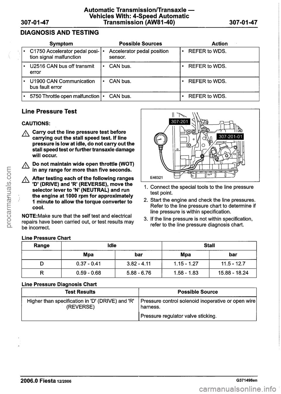
Line Pressure Test
C1750 Accelerator pedal posi-
tion signal malfunction
. CAN bus.
CAUTIONS:
A Carry out the line pressure test before
carrying out the stall speed test.
If line
pressure is low at idle, do not carry out the
stall speed test or further transaxle damage
will occur.
Accelerator pedal position
sensor.
A Do not maintain wide open throttle (WOT)
in any range for more than five seconds.
REFER to WDS.
A After testing each of the following ranges
ID' (DRIVE) and 'R' (REVERSE)r move the 1. Connect the special tools to the line pressure selector lever to 'N' (NEUTRAL) and run
the engine at
I000 rpm for approximately test point.
i, 1 minute to allow the torque converter to 2. Start the engine and check the line pressures.
cool. Refer to the line pressure chart to determine if -- --- line pressure is within specification. N0TE:Make sure that the self test and electrical 3m If the line pressure is not within specification, repairs have been carried out, or test results may
be incorrect. refer to the
line pressure diagnosis chart.
Line Pressure Chart
Range
Idle Stall
R 0.59 - 0.68 5.88 - 6.76 1.58 - 1.83 15.88 - 18.24
Line Pressure Diagnosis Chart
I I Pressure regulator valve sticking. I
Test Results
Higher than specification in 'D' (DRIVE) and 'R'
(REVERSE)
2006.0 Fiesta 1212006 G371498en
Possible Source
Pressure control solenoid inoperative or open wire
harness.
procarmanuals.com
Page 1015 of 1226

Automatic Transmission/Transaxle -
Vehicles With: 4-Speed Automatic
307101 -55 Transmission (AW81-40) 307-01 -55
IN-VEHICLE REPAIR
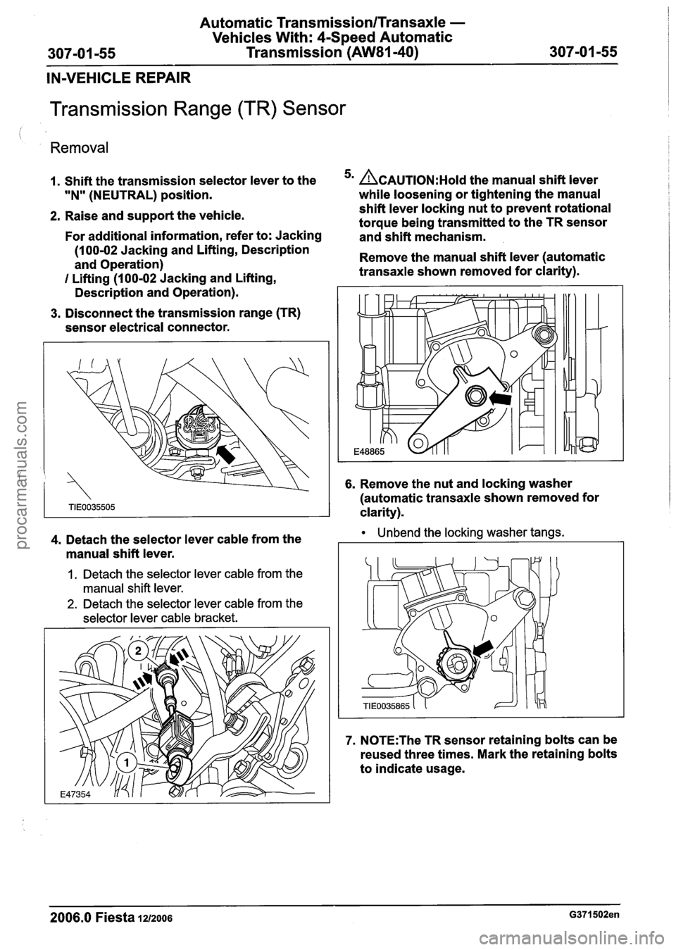
Transmission Range (TR) Sensor
Removal
1. Shift the transmission selector lever to the ACAUTION:H~I~ the manual shift lever
"N" (NEUTRAL) position. while loosening
or tightening the manual - -
2. Raise and support the vehicle. shift
lever locking nut to prevent rotational
torque being transmitted to the TR sensor
For additional information, refer to: Jacking
and shift mechanism.
(1
00-02 Jacking and Lifting, Description
and Operation) Remove
the manual shift lever (automatic
I Lifting (1 00-02 Jacking and Lifting, transaxle
shown removed for clarity).
Description and Operation).
3. Disconnect the transmission range (TR)
sensor electrical connector.
6. Remove the nut and locking washer
(automatic transaxle shown removed for
clarity).
4. Detach the selector lever cable from the Unbend the locking washer tangs.
manual shift lever.
1. Detach the selector lever cable from the
manual shift lever.
2. Detach the selector lever cable from the
selector lever cable bracket.
7. N0TE:The TR sensor retaining bolts can be
reused three times. Mark the retaining bolts
to indicate usage.
2006.0 Fiesta 1212006 G371502en
procarmanuals.com
Page 1017 of 1226
Automatic Transmission/Transaxle -
Vehicles With: 4-Speed Automatic
307-01 -57 Transmission (AW81-40) 307-01 -57
IN-VEHICLE REPAIR
A~old the manual shift lever while 8. Lower the vehicle.
' tightening the manual shift lever locking nut 9. Check the selector lever cable adjustment to prevent rotational torque being by
moving the transmission selector lever
transmitted to the
TR sensor and shift through
all gear ranges.
mechanism.
Install the manual shift lever (automatic
transaxle shown removed for clarity).
6. Connect the TR sensor electrical connector.
7. Attach the selector lever cable to the manual
shift lever.
1. Attach the selector lever cable to the selector
lever cable bracket.
2. Attach the selector lever cable to the manual
shift lever.
2006.0 Fiesta 1212006 G371502en
procarmanuals.com