2007 FORD FIESTA body system
[x] Cancel search: body systemPage 814 of 1226

Fuel Charging and Controls - 2.OL
303-04B-6 Duratec-HE (M14) 303-04B-6
DIAGNOSIS AND TESTING
1 6 1 Heated Oxygen sensor (H02s) I
Item Description Fuel supply
1 7 1 Intake manifold I
5
Fuel injectors
Throttle body
The fuel supply for all petrol fueled variants is
equipped with a return-less fuel system. This
means that the fuel delivery pressure at the fuel
injectors, is monitored and controlled by the fuel
tank module. This control is achived by switching
the fuel pump on and off.
The fuel pump module for both the Ethanol E85
TO maintain the same or similar power output to variant vehicle and the unleaded fueled vehicle are
that of the unleaded fuel vehicle, the fuel injectors
very similar, visual^ the only difference is the fuel
have been replaced with high flow fuel injectors. pump electrical connections which on the Ethanol
E85 variant is sealed. This is not the only
differance, both fuel pump modules have different
(
Fuel composition monitoring fuel level sensor resistor card values.
The quantity of Ethanol E85 in relation to the
quantity of unleaded fuel contained in the fuel tank
at any one time is not monitored at the fuel tank.
The Ethanol percentage volume can only decrease
from its maximum 85% (pure Ethanol
E85), to zero
(1 00% unleaded fuel).
The fuel charging system compensates for the
changes in fuel composition using the signal
received by the power train control module (PCM)
from the
H02s. The PCM adapts the fueling and
ignition calibrations to suit the current fuel tank
content composition.
Cold start
To overcome the problems relating to cold start
inherent with Ethanol E85 vehicles (temperatures
down to -29 degrees centigrade), a block heater
has been installed into the engine coolant system.
The block heater is located to the rear of the engine
under the exhaust manifold. The block heater is
fitted with a dedicated harness which terminates at an external plug connector fitted into the radiator
grill.
2006.0 Fiesta 1212006
procarmanuals.com
Page 874 of 1226

303-06-1 0 Starting System 303-06-1 0
DIAGNOSIS AND TESTING
TEST CONDITIONS DETAILSIRESULTSIACTIONS
Measure the voltage between the starter motor
terminal 30, component side and the battery
positive
terminal.
Is the voltage less than 0.5 volts?
+ Yes
GO to C2.
+ No
CLEAN and TIGHTEN all battery positive
cable connections. TEST the system for
normal operation. If the concern persists,
INSTALL a new battery to starter motor
solenoid cable.
REFER to: Battery to Starter Motor Solenoid
Cable - 1.3L Duratec-8V (Rocam) (41 4-01
Battery, Mounting and
Cables, Removal and
Installation)
1 Battery to Starter Motor Solenoid Cable -
1.25L Duratec-1 6V (Sigma)/l.4L Duratec-
16V (Sigma)/l.6L Duratec-1 6V (Sigma)
(414-01 Battery, Mounting and
Cables,
Removal and Installation).
Test the system for normal operation. - - ---
I C2: CHECK FOR GROUND CONNECTION
-
I f
Ignition switch in position Ill.
Is the voltage less than 0.5 volts?
-, Yes
CHECK the battery.
REFER to: Charging System (414-00 Char-
ging System
- General Information,
Diagnosis and Testing).
TEST the system for
normal operation.
+ No
CLEAN and TIGHTEN all battery ground cable
connections, starter motor mounting and body
to ground straps. TEST the system for
normal
operation. If the concern persists, INSTALL a
new battery ground
cable. Testlhe system for
normal operation.
2006.0 Fiesta 1212006 GI 51 301 en
procarmanuals.com
Page 941 of 1226

303-1 4-1 7 Electronic Engine Controls 303-1 4-1 7
DIAGNOSIS AND TESTING
The DTC is always a 5 digit alphanumerical
code, for example
"POI 00".
The first digit of a code (letter) identifies the
system which has set the code. Provision has
been made for a total of four systems to be
identified although only the
'PI code is required
for EOBD.
- 'B' for the body
- 'C' for the chassis
- 'P' for the powertrain
- 'U' for the network communications systems
All of the
"xOxxxW codes are standardized codes.
However, any manufacturer can use additional
codes over and above the standardized codes.
These will be labelled
"xlxxx"
The third digit of a code (numeric) identifies the
sub-system which has set the code.
- 'Pxlxx' for metering of fuel and air supply
- 'Px2xx' for metering of fuel and air supply
- 'Px3xx' for ignition system - combustion
misfires
- 'Px4xx' for auxiliary emission control
equipment
- 'Px5xx' for vehicle speed, idle setting and
other related inputs
- 'Px6xx' for trip computer and other related
outputs
- 'Px7xx' for transmission.
- 'Px8xx' for transmission.
- 'Px9xx' category to be determined
- 'PxOxx' category to be determined
When a concern occurs, the actions taken
include storage of the relevant information and
actuation of the MIL occurs in line with the
relevant legislation.
MIL Code List
I PO030 I Heated oxygen sensor (H02S) heater open circuit I
! '
-1 H02S heater low voltage I
I PO032 I H02S heater high voltage I
MILCode
PO036 1- ' Catalyst monitor sensor heater open circuit I
Description
PO037
I PO054 I Catalyst monitor sensor heater resistance out of limits I
Catalyst monitor sensor heater low voltage
PO038
PO053
I PO106 I Manifold absolute pressure (MAP) sensor plausibility malfunction I
-
Catalyst monitor sensor heater high voltage
H02S heater resistance out of limits
I PO107 I MAP sensor circuit low input I
PO108
PO1 09 MAP sensor
circuit high input
MAP sensor temporary malfunction
PO1 12
PO113
I PO117 I ECT circuit low input I
Intake air temperature (IAT) circuit low input
IAT circuit high input
I
2006.0 Fiesta 1212006 G384566en
PO114
PO1 16
PO118
IAT intermittent failure
Engine coolant temperature (ECT) signal stuck at low level
ECT circuit high input
procarmanuals.com
Page 944 of 1226

303-1 4-20 Electronic Engine Controls 303-1 4-20
DIAGNOSIS AND TESTING
1 PO643 1 Transmission sensor power supply 1 high voltage I
MIL Code
PO641
PO642
1 PO646 1 Air conditioning (NC) clutch relay circuit low voltage I
1 PO647 1 NC clutch relay circuit high voltage I
Description
Transmission sensor power supply 1 noisy signal
Transmission sensor power supply
I low voltage
I PO651 I Transmission sensor power supply 2 noisy signal I
i
PO652
PO653
Transmission sensor power supply 2 low voltage
Transmission sensor power supply
2 high voltage
PO654
PO686
1 PO692 1 Cooling fan 1 control circuit high voltage I
Engine run output circuit malfunction
Main relay malfunction low voltage
PO687
PO691
1 PO693 1 Cooling fan 2 control circuit low voltage I
Main relay malfunction high voltage
Cooling fan
1 control circuit low voltage
1 PO694 1 Cooling fan 2 control circuit high voltage I
I PI500 I Vehicle speed sensor (VSS) output circuit malfunction I
PO704
PI 000
Generator command malfunction I
Clutch switch implausible signal
EOBD system readiness test not complete
I P2107 I Safety failure level 3 I
PI 794
P2100
I P2108 I Safety failure level 2 error I
Battery voltage malfunction too high or too low
Engine throttle body H-bridge malfunction
APP sensor circuit 1 high input I
P2119
P2122
1 P2127 1 APP sensor circuit 2 low input I
Engine throttle body throttle flap malfunction
Accelerator pedal position (APP) sensor circuit
1 low input
1 P2128 1 APP sensor circuit 2 high input I
1 P2176 1 Engine throttle body adaptive algorithm failed 1
P2128
P2135
APP sensor circuits I and 2 plausibility error
TP sensor circuits 1 and 2 plausibility error
I UOOOl I Control Area Network (CAN) bus-off or mute I
P2280
P2282
I UOlOl I CAN missing frame from TCU I
Air cleaner obstruction or leakage
Air leakage between throttle and inlet valves
2006.0 Fiesta 1212006 G384566en
procarmanuals.com
Page 961 of 1226

Automatic Transmission/Transaxle .
Vehicles With: 4-Speed Automatic
Transmission
(AW81-40)
SECTION 307-01 Automatic Transmission/Transaxle
. Vehicles With: 4-Speed Automatic Transmission
(AW81-40)
VEHICLE APPLICATION:2006.0 Fiesta
CONTENTS PAGE
SPECIFICATIONS
Specifications
........................................................................\
.............................................. 307-0 1 -3
DESCRIPTION AND OPERATION
Automatic Transaxle
........................................................................\
...................................
Transmission cross-section ........................................................................\
........................
Torque converter with Torque Converter Clutch (TCC) ......................................................
Fluid pump and stator shaft ........................................................................\
........................
........................................................................\
......... Planetary gearset ......................... .:
Clutches and brakes ........................................................................\
...................................
Intermediate gear stage and differential assembly .............................................................
Main control body ........................................................................\
.......................................
Internal' gearshift mechanism ........................................................................\
.....................
Fluid circuit ........................................................................\
.................................................
........................................................................\
....................................... Identification Tags
Type plate
........................................................................\
...................................................
Transmission Ranges and Power Flow ........................................................................\
......
Transmission ratio and power flow route - 1st gear ............................................................
Transmission ratio and power flow route - 2nd gear ..........................................................
Transmission ratio and power flow route . 3rd gear ...........................................................
Transmission ratio and power flow route . 4th gear ...........................................................
Transmission ratio and power flow route . reverse gear ....................................................
Transaxle Electronic Control System ........................................................................\
..........
........................................................................\
..................................................... Overview
Transmission control unit
........................................................................\
............................
........................................................................\
.................................... Gearshift strategies
Selector lever positions
........................................................................\
..............................
Signal transmission on the CAN databus ........................................................................\
...
........................................................................\
...................................................... Sensors
........................................................................\
.................................................... Actuators
DIAGNOSIS AND TESTING
Automatic Transaxle
........................................................................\
................................... 307-01
Inspection and Verification ........................................................................\
.................... 307-01
Diagnostic Trouble Code Chart
........................................................................\
.................. 307-01
........................................................................\
...................................... Line Pressure Test 307-01
Stall Speed Test
........................................................................\
....................................... 307-01
Time Lag Test
........................................................................\
............................................. 307-01
procarmanuals.com
Page 1063 of 1226

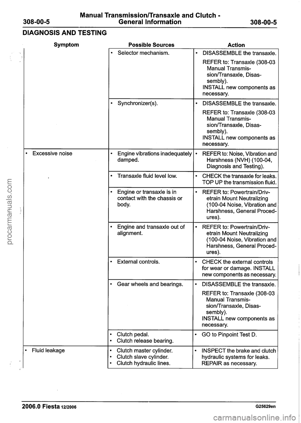
Manual Transmission/Transaxle and Clutch -
308-00-5 General Information 308-00-5
DIAGNOSIS AND TESTING
Symptom
Excessive noise Possible Sources
Action
Selector mechanism.
DISASSEMBLE the transaxle.
REFER to: Transaxle (308-03 Manual Transmis-
sionITransaxle, Disas-
sem bly).
INSTALL new components as
necessary.
DISASSEMBLE the transaxle.
REFER to: Transaxle (308-03 Manual Transmis-
sionITransaxle, Disas-
sem bly).
INSTALL new components as
necessary.
Engine vibrations inadequately
damped.
REFER to: Noise, Vibration and
Harshness (NVH) (1 00-04,
Diagnosis and Testing).
Transaxle fluid level low. CHECK the transaxle for leaks.
I TOP UP the transmission fluid.
Engine or transaxle is in
contact with the chassis or
body. REFER
to:
PowertrainIDriv-
etrain Mount Neutralizing
(1 00-04 Noise, Vibration and
Harshness, General Proced-
u res)
.
Engine and transaxle out of
alignment. REFER
to: PowertrainIDriv-
etrain Mount Neutralizing
(I 00-04 Noise, Vibration and
Harshness, General Proced-
u res)
.
External controls. CHECK the external controls
for wear or damage. INSTALL
new components as necessary.
Gear wheels and bearings.
DISASSEMBLE the transaxle.
REFER to: Transaxle (308-03
Manual Transmis-
sion/-rransaxle, Disas-
sem bly).
INSTALL new components as
necessary.
Clutch pedal. I GO to Pinpoint Test D.
Clutch release bearing.
Fluid leakage Clutch master cylinder.
Clutch slave cylinder.
Clutch hydraulic lines.
INSPECT the brake and clutch
hydraulic systems for leaks.
REPAIR as necessary.
2006.0 Fiesta 1212006 G25629en
procarmanuals.com
Page 1193 of 1226

31 0-00-7 Fuel System - General Information 31 0-00-7
GENERAL PROCEDURES
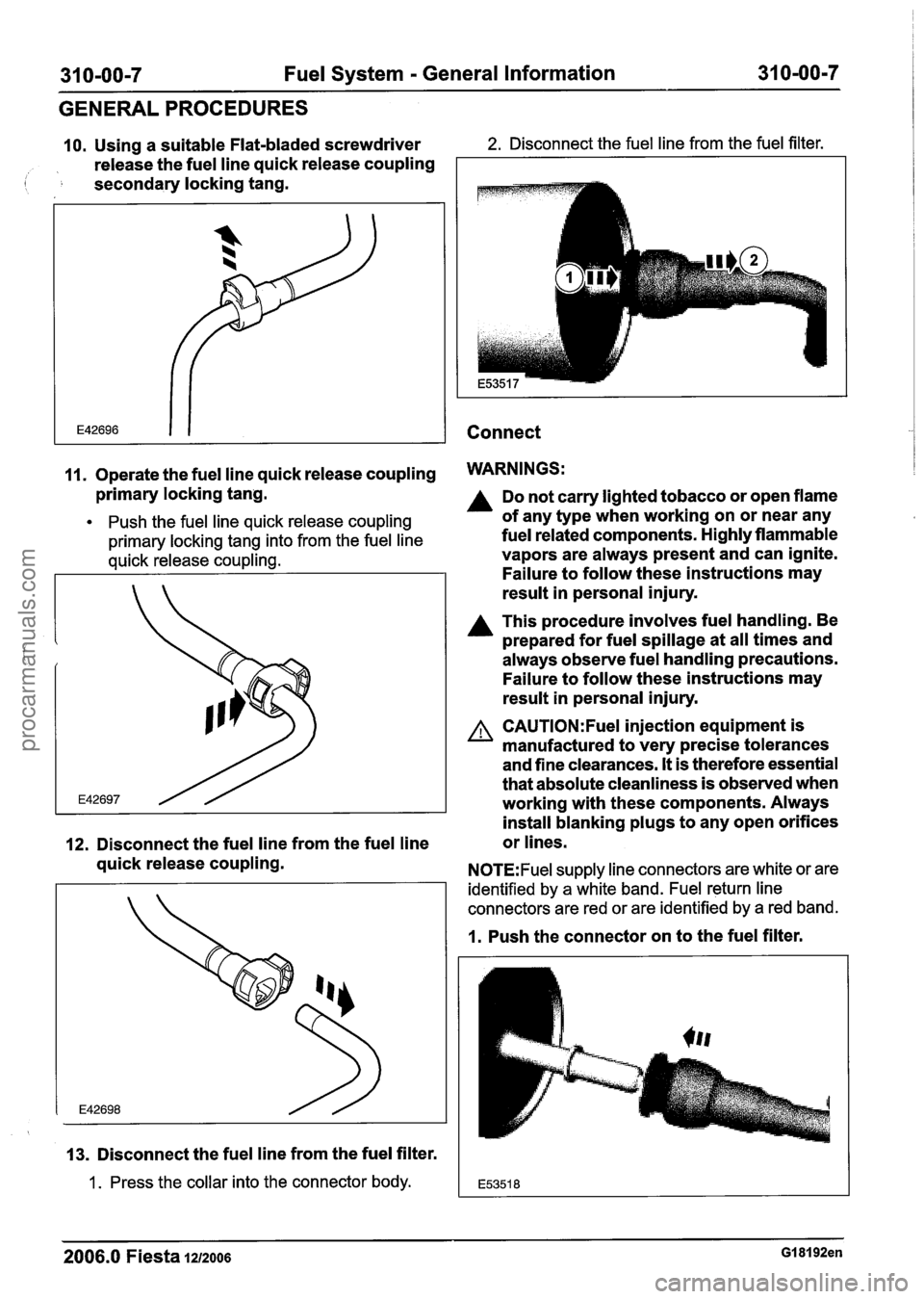
10. Using a suitable Flat-bladed screwdriver 2. Disconnect the fuel line from the fuel filter.
release the fuel line quick release coupling
( secondary locking tang.
Connect
11. Operate the fuel line quick release coupling WARNINGS:
primary locking tang.
Push the fuel line quick release coupling
primary locking tang into from the fuel line
quick release coupling.
12. Disconnect the fuel line from the fuel line
quick release coupling.
13. Disconnect the fuel line from the fuel filter.
1 . Press the collar into the connector body.
Do not carry lighted tobacco or open flame
of any type when working on or near any
fuel related components. Highly flammable
vapors are always present and can ignite.
Failure to follow these instructions may
result in personal injury.
A This procedure involves fuel handling. Be
prepared for fuel spillage at all times and
always observe fuel handling precautions.
Failure to follow these instructions may
result in personal injury.
A CAUTI0N:Fuel injection equipment is
manufactured to very precise tolerances
and fine clearances.
It is therefore essential
that absolute cleanliness is observed when
working with these components. Always
install blanking plugs to any open orifices
or lines.
N0TE:Fuel supply line connectors are white or are
identified by a white band. Fuel return line
connectors are red or are identified by a red band.
1. Push the connector on to the fuel filter.
2006.0 Fiesta 1212006 GI 81 92en
procarmanuals.com
Page 1217 of 1226

Acceleration Control - I .3L Duratec-8V
(Rocam)llI25L Duratec-I 6V (Sigma)ll.4L
Duratec-1 6V (Sigma)ll .6L Duratec-1 6V (Sigma)
DIAGNOSIS AND TESTING
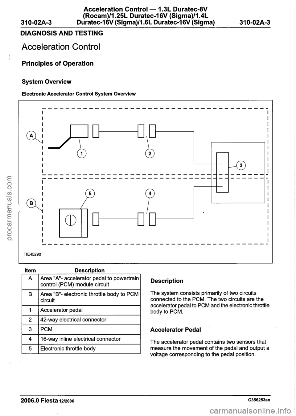
Acceleration Control
Principles of Operation
System Overview
Electronic Accelerator Control System Overview
Item Description
A Area "A- accelerator pedal
to powertrain
1 I control (PCM) module circuit Description
B Area "B"- electronic throttle body to PCM
I I circuit
I 1 I Accelerator pedal I
The system consists primarily of two circuits
connected to the PCM. The two circuits are the
accelerator pedal to PCM and the electronic throttle
body to PCM.
1 3 ~PCM I Accelerator Pedal
2006.0 Fiesta 1212006 G356253en
4
5
voltage corresponding to the pedal position.
16-way
inline electrical connector
Electronic throttle body The accelerator pedal contains two sensors
that
measure the movement of the pedal and output a
procarmanuals.com