Page 921 of 1226
303-1 3-3 Evaporative Emissions 303-1 3-3
DIAGNOSIS AND TESTING
Evaporative Emissions
i
Inspection and Verification
1. Verify the customer concern.
2. Visually inspect for obvious signs of mechanical
or electrical damage.
Visual Inspection Chart
I Mechanical I Electrical I
- Vacuum line(s)
- Evaporative emis-
sion (EVAP) system
canister
- EVAP system
hose(s)
- EVAP system
canister purge valve
I - Fuse(s) I I - Wiring harness
- Electrical
connector(s)
3. If an obvious cause for an observed or reported
concern is found, correct the cause (if possible)
before proceeding to the next step.
4. If the cause is not visually evident, verify the
i
' symptom and refer to WDS to diagnose the
' system.
2006.0 Fiesta 12/2006 G28748en
procarmanuals.com
Page 1005 of 1226

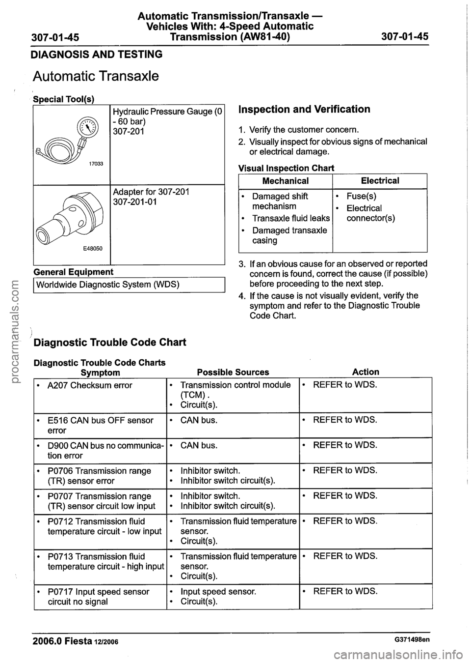
Automatic Transmission/Transaxle -
Vehicles With: 4-Speed Automatic Transmission
(AW81-40)
DIAGNOSIS AND TESTING
Automatic Transaxle
Special Tool(s)
Hydraulic Pressure Gauge (0
- 60 bar)
307-20 1
General Equipment Worldwide
~ia~noitic System (WDS)
Inspection and Verification
1. Verify the customer concern.
2. Visually inspect for obvious signs of mechanical
or electrical damage.
Visual
lns~ection Chart
I Mechanical I Electrical I
3. If an obvious cause for an observed or reported
concern is found, correct the cause (if possible)
before proceeding to the next step.
4. If the cause is not visually evident, verify the
symptom and refer to the Diagnostic Trouble
Code Chart.
Damaged shift
mechanism
Transaxle fluid leaks
Damaged transaxle
casing
.I
- Diagnostic Trouble Code Chart
Fuse(s)
Electrical
connector(s)
Diagnostic Trouble Code Charts
Symptom Possible Sources Action
I A207 Checksum error I Transmission control module I REFER to WDS.
E516 CAN bus OFF sensor
error CAN bus.
D9OO CAN bus no communica-
tion error
PO706 Transmission range
(TR) sensor error
PO707 Transmission range
(TR) sensor circuit low input
CAN bus.
Inhibitor switch.
Inhibitor switch circuit(s).
lnhibitor switch.
lnhibitor switch circuit(s).
PO712 Transmission fluid
temperature circuit
- low input
REFER to WDS.
REFER to WDS.
3 Transmission fluid
temperature circuit
- high input
2006.0 Fiesta 1212006 G371498en
Transmission fluid temperature
sensor.
Circuit(s).
PO71 7 lnput speed sensor
circuit no signal
REFER to WDS.
Transmission fluid temperature
sensor.
e Circuit(s).
lnput speed sensor.
Circuit(s).
REFER to WDS.
procarmanuals.com
Page 1189 of 1226
31 0-00-3 Fuel System - General Information 31 0-00-3
GENERAL PROCEDURES
/'
Fuel System Pressure Release(23 420 0)
i
Release
I. WARNINGS:
ADO not smoke or carry lighted tobacco or
open flame of any type when working on or
near any fuel related components. Highly
flammable vapors are always present and
may ignite. Failure to follow these
instructions may result in personal injury.
A~he fuel system remains pressurized for
a long time after the ignition is switched off.
The fuel pressure must be released before
attempting any repairs. Failure to follow this
instruction may result in personal injury.
Remove the fuel pump fuse.
2. Start the engine and allow to idle until the
engine stalls.
3. Crank the engine for approximately five
seconds to make sure the fuel injection
supply manifold pressure has been released.
,1 4. Install the fuel pump fuse.
2006.0 Fiesta 1212006 GI 81 91 en
procarmanuals.com
Page 1220 of 1226

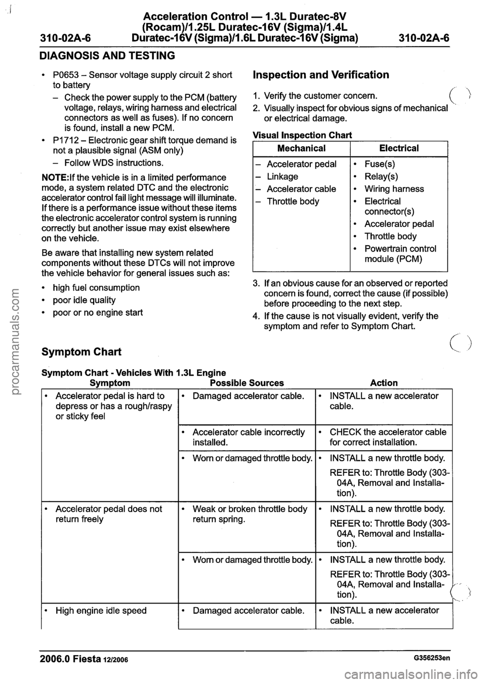
Acceleration Control - I .3L Duratec-8V
(Rocam)llI25L Duratec-I 6V (Sigma)llI4L
31 0-02A-6 Duratec-I 6V (Sigma)/l .6L Duratec-1 6V (Sigma)
31 0-02A-6
DIAGNOSIS AND TESTING
PO653 - Sensor voltage supply circuit 2 short Inspection and Verification
to battery
- Check the power supply to the PCM (battery 1. Verify the customer concern.
voltage, relays, wiring harness and electrical 2. Visually inspect for obvious signs of mechanical
connectors as well as fuses). If no concern
or electrical damage.
- Follow WDS instructions. I - Accelerator pedal I Fuse(s) I
- is found, install a new PCM.
PI 71 2 - Electronic gear shift torque demand is Visual
Inspection Chart
N0TE:lf the vehicle is in a limited performance
mode, a system related DTC and the electronic
accelerator control fail light message will illuminate.
If there is a performance issue without these items
the electronic accelerator control system is running
correctly but another issue may exist elsewhere
on the vehicle.
not
a plausible signal (ASM only) - Linkage
- Accelerator cable
- Throttle body
Relay(s)
Wiring harness
Electrical
connector(s)
Accelerator pedal
Throttle body
Mechanical
Electrical
Symptom Chart < .I
Be
aware that installing new system related
components without these
DTCs will not improve
Symptom Chart
- Vehicles With 1.3L Engine
Symptom Possible Sources
Powertrain control
module (PCM)
Action
the
vehicle behavior for general issues such as:
high fuel consumption 3.
If an obvious cause for an observed or reported
concern is found, correct the cause (if possible)
poor idle quality before proceeding to the next step.
poor or no engine start
4. If the cause is not visually evident, verify the
symptom and refer to Symptom Chart.
f
Accelerator pedal is hard to
depress or has a
roughlraspy
or sticky feel
Damaged accelerator cable.
REFER to: Throttle Body (303-
04A, Removal and Installa-
tion).
INSTALL a new accelerator
cable.
Accelerator cable incorrectly installed.
Worn or damaged throttle body.
I Accelerator pedal does not I Weak or broken throttle body I INSTALL a new throttle body. I
CHECK the accelerator cable
for correct installation.
INSTALL a new throttle body.
return freely REFER to: Throttle Body (303-
04A, Removal and Installa-
tion).
I Worn or damaged throttle body. I INSTALL a new throttle body. I
I I I REFER to: Throttle Body (303- 1 04A, Removal and Installa-
tion).
High engine idle speed Damaged accelerator cable. INSTALL a new accelerator
I cable.
2006.0 Fiesta 1212006 G356253en
procarmanuals.com
Page 1226 of 1226

I <:: .
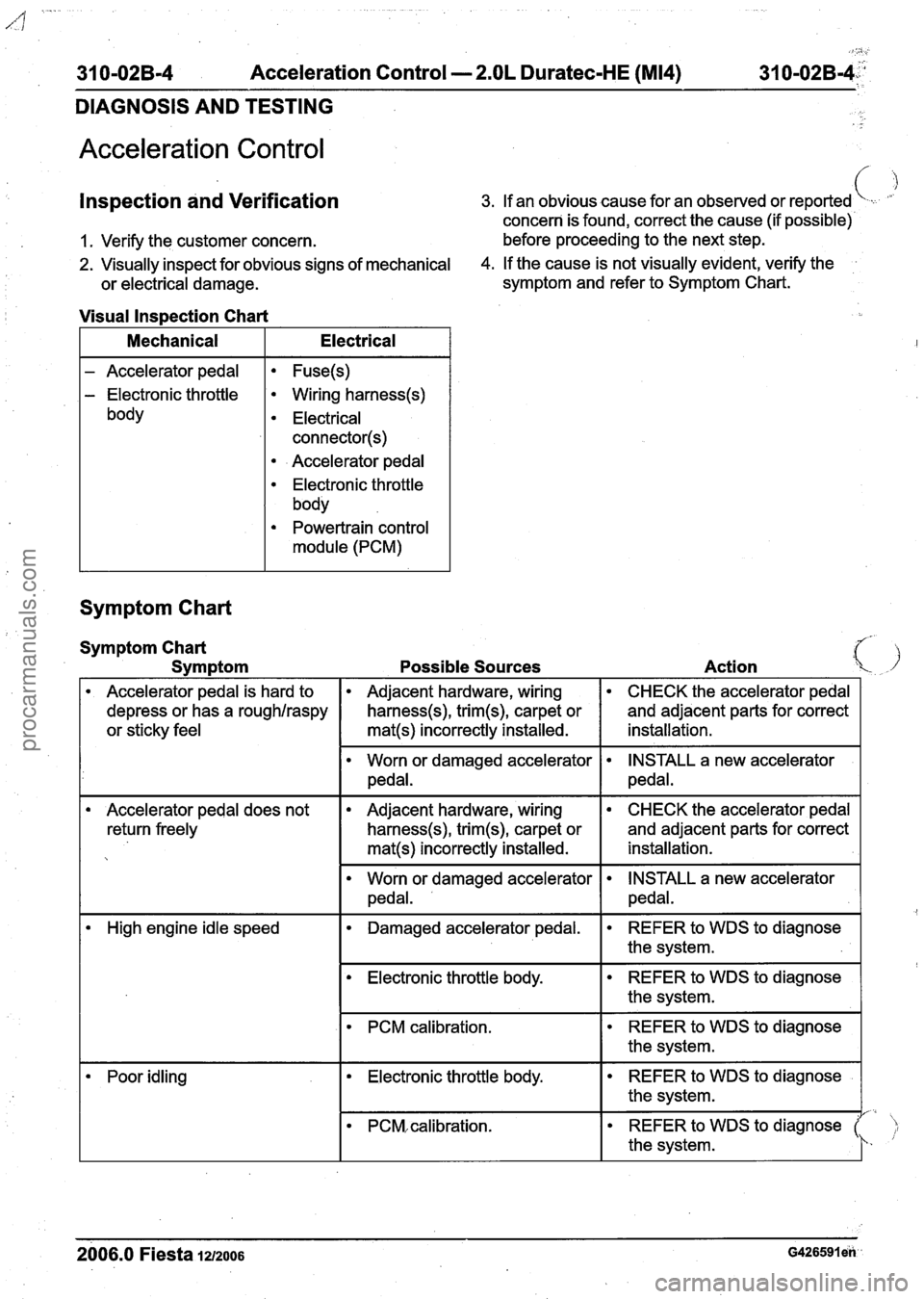
31 0-02B-4 Acceleration Control - 2.OL Duratec-HE (M14) 31 0-02~-4::'
DIAGNOSIS AND TESTING
Acceleration Control
lnspection and Verification
1. Verify the customer concern.
3. If an obvious cause for an observed or reported \.
concern is found, correct the cause (if possible)
before proceeding to the next step.
2. Visually inspect for obvious signs of mechanical 4. If the cause is not visually evident, verify the
or electrical damage. symptom
and refer to Symptom Chart.
Visual lnspection Chart
I Mechanical I Electrical I
- Accelerator pedal
- Electronic throttle
body
Fuse(s)
Wiring harness(s)
Electrical
connector(s)
Accelerator pedal
Electronic throttle
body
Powertrain control
module (PCM)
Symptom Chart
Accelerator pedal does not
return freely
Symptom Chart
Symptom Possible Sources Action
Accelerator pedal is hard to
depress or has a roughlraspy
or sticky feel
Adjacent hardware, wiring
harness(s), trim(s), carpet or
mat(s) incorrectly installed.
High engine idle speed
Adjacent hardware, wiring
harness(s), trim(s), carpet or
mat(s) incorrectly installed.
Worn or damaged accelerator
pedal.
CHECK the accelerator pedal
and adjacent parts for correct
installation.
worn or damaged accelerator
pedal. CHECK the
accelerator pedal
and adjacent parts for correct
installation.
INSTALL a new accelerator
pedal.
INSTALL a new accelerator
pedal.
Electronic throttle body. REFER to WDS to diagnose
the system.
Damaged
accelerator pedal.
I PCM calibration. REFER
to WDS to diagnose
the system.
REFER to WDS to diagnose
the system.
Poor idling I Electronic throttle body.
- - - - - - - -
2006.0 Fiesta 121200s ~426591 en
REFERto WDS todiagnose
the system.
PCM, calibration.
REFER to WDS to diagnose ),
1- ' the system.
procarmanuals.com