Page 393 of 1226

211 -02-45 Power Steering 21 1-02-45
REMOVAL AND INSTALLATION
Attach the tie-rod end to the wheel knuckle 21. Install the wheels and tires.
on both sides.
For additional information, refer to: Wheel
and Tire (204-04 Wheels and Tires,
Removal and Installation).
22m AwARNING:~~~~~~~ a new steering column
to steering gear pinion retaining bolt.
Failure to follow this instruction may result
in personal injury.
19.
N0TE:Use a 5mm Allen key to prevent the
stabilizer bar connecting link ball joint stud
from rotating.
Attach the stabilizer bar connecting link to
the stabilizer bar on both sides. Attach
the steering column shaft to the
steering gear pinion.
23. Fill and bleed the power steering system.
For additional information, refer to: (211 -00
Steering System
- General Information)
Power Steering System Filling (General
Procedures),
Power Steering System Filling
- I .6L
Duratorq-TDCi (DV) Diesel (General
Procedures),
Power Steering System Bleeding (General
20.
N0TE:Make sure that the collar on the hose Procedures),
is inserted fully into the quick release Power Steering System
Bleeding - 1.6L
coupling. Duratorq-TDCi (DV) Diesel (General
Procedures).
Connect the power steering fluid reservoir
return hose quick release coupling. 24.
Check the toe setting and adjust as
necessary. For additional information, refer
to: (204-00 Suspension System
- General
Information)
Specifications (Specifications),
Front Toe Adjustment (General Procedures).
2006.0 Fiesta 1212006 GI 05648en
procarmanuals.com
Page 397 of 1226

21 1 -02-49 Power Steering 21 I -02-49
REMOVAL AND INSTALLATION
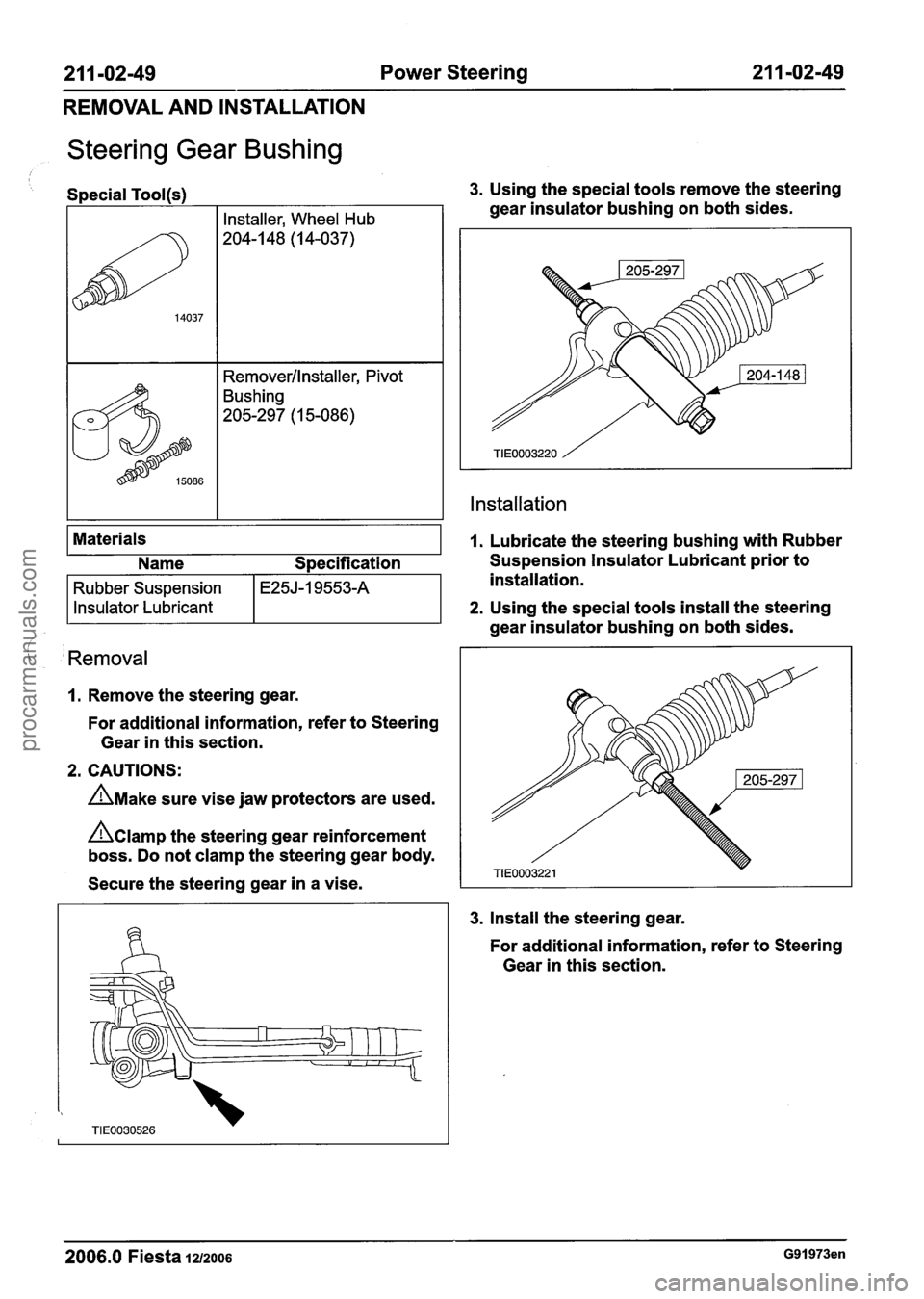
Steering Gear Bushing
/ I
Special Tool(s) 3. Using the special tools remove the steering
( 'Removal
1. Remove the steering gear.
For additional information, refer to Steering
Gear in this section.
2. CAUTIONS:
A~ake sure vise jaw protectors are used.
hamp the steering gear reinforcement
boss. Do not clamp the steering gear body.
Secure the steering gear in a vise.
Materials
3. Install the
steering gear.
gear
insulator bushing on both sides.
Installation
14037
1. Lubricate the steering bushing with Rubber
For additional information, refer to Steering
Gear in this section.
Installer, Wheel Hub
204-1 48 (1 4-037)
Removerllnstaller, Pivot
Bushing
205-297 (1 5-086)
2006.0 Fiesta 1212006 G91973en
Name Specification Suspension Insulator Lubricant prior to
installation.
2. Using the special tools install the steering
Rubber Suspension
Insulator Lubricant
gear insulator bushing on both sides.
E25J-I 9553-A
procarmanuals.com
Page 402 of 1226

211 -03-4 Steering Linkage 21 1-03-4
REMOVAL AND INSTALLATION
Tie Rod End(l3 273 0)
Special Tool(s)
I Separator, Ball Joint
2. Remove and discard the tie-rod end retaining (,,
nut.
Removal
1. Remove the wheel and tire.For additional
information, refer to Section 204-00
[Suspension System
- General Information].
4. N0TE:Make a note of the number of turns
2m &AUTION:L~~~~ the tie-rod end retaining used to remove the tie-rod endrn
nut in place to protect the ball joint stud.
Remove the tie-rod end.
N0TE:Use a 5 mm Allen key to prevent the ball
joint stud from rotating.
Loosen the tie-rod end locknut and the
tie-rod end retaining nut.
1. Loosen the locknut.
2. Loosen the retaining nut.
3m &Au~l~N:~rotect the ball joint seal using
a soft cloth to prevent damage.
Using the special tool, detach the tie-rod end
from the wheel knuckle.
1. Release the tie-rod end.
Installation
I. N0TE:lnstall the tie-rod end using the same
number of turns used to remove
it.
Install the tie-rod end.
2006.0 fiesta 12,2006 GI 05650en
procarmanuals.com
Page 403 of 1226
21 1 -03-5 Steering Linkage 21 1 -03-5
REMOVAL AND INSTALLATION
2m AwARNING:~~~~~~~ a new tie-rod end
/ I retaining nut. Failure to follow this
instruction may result in personal injury.
N0TE:Use a 5 mm Allen key to prevent the ball
joint stud from rotating.
Attach the tie-rod end to the wheel knuckle.
1. Tighten the retaining nut.
2. Tighten the locknut.
3. Install the wheel and tire.For additional
information, refer to Section 204-00
f ' [Suspension System - General Information]. ' ' 4. Check the toe setting and adjust as
necessary. For additional information, refer
to Section 204-00 [Suspension System
-
General Information].
- - --
2006.0 Fiesta 1212006 GI 05650en
procarmanuals.com
Page 484 of 1226

Engine - I .25L Duratec-1 6V (Sigma)llI4L
Duratec-1 6V (Sigma)ll .6L Duratec-I 6V (Sigma)
SPECIFICATIONS
1 Description I Nm I Ib-ft I Ib-in I
I Camshaft pulley retaining bolt I 60 I 44 I - I
Timing belt tensioner two bolts fixing
Timing belt tensioner central bolt fixing
Crankshaft position (CKP) sensor bracket to
cylinder block retaining bolts
I Crankshaft rear oil seal carrier retaining bolts I 9 1 - I 80 I
20
25
I Cylinder block blanking plug I 20 I 15 1 - I
I Crankshaft pulley retaining bolt I a) I - I - I
15
18
I Engine coolant temperature (ECT) sensor I 18 I 13 I - I
-
-
I Exhaust manifold studs I 10 I - I 89 I
Positive crankcase ventilation (PCV) cover retaining
1 bolts Fuel
rail to intake manifold
Knock sensor (KS) retaining bolt
I Thermostat housing retaining bolts I 9 I - 1 80 I
I Flywheel to crankshaft retaining bolts I a) I - I - I
15
20
I Selector lever cable bracket to transaxle I 20 I 15 I I
11
15
Transaxle retaining bolts
Torque converter retaining nuts
I Intermediate shaft center bearing cap retaining nuts 1 25 I 18 I - I
-
-
I Ground cable to cylinder head retaining bolt I 18 I 13 I - I
47
27
Suspension strut and spring assembly top mount
retaining nuts
I a) Refer to procedure in this section.
35
20
2006.0 Fiesta 1212006 GI 54208en
-
procarmanuals.com
Page 922 of 1226

303-1 34 Evaporative Emissions 303-1 3-4
REMOVAL AND INSTALLATION
Evaporative Emission Canister - 1.3L Duratec-8V (Rocam)/l.25L
Duratec-1 6V (Sigma)/l.4L Duratec-I 6V (Sigma)/l .6L
Duratec-1
6V (Sigma)(29 250 0)
c
General Equipment 3. Detach the exhaust system from the center
Transmission jack exhaust hanger insulator.
Removal
WARNINGS:
A Do not smoke or carry lighted tobacco or
open flame of any type when working on
or near fuel related components. Highly
flammable vapors are always present and
may ignite. Failure to follow these
instructions may result in personal injury.
A This procedure involves fuel handling. Be
prepared for fuel spillage at all times and
always observe fuel handling precautions.
4. N0TE:When detaching the exhaust system
Failure to follow these instructions may
allow the system to be supported by the rear
result in personal injury.
suspension assembly.
I. Raise and support the vehicle. For additional
Detach the exhaust system from the rear
information, refer to Section
100-02 [Jacking
exhaust hanger insulator.
and Lifting].
2. Remove the floor panel crossmember.
5. Remove the exhaust system heat shield.
-
2006.0 Fiesta 1212006 G210050en
procarmanuals.com
Page 1204 of 1226

31 0-01 -6 Fuel Tank and Lines 31 0-01 -6
REMOVAL AND INSTALLATION
Fuel Tank(23 554 0)
Special Tool(s)
I I Wrench, Sender Unit, Fuel
General Equipment
I Transmission jack I
Removal
All vehicles
WARNINGS:
A Do not smoke or carry lighted tobacco or
open flame of any type when working on
or near fuel related components. Highly
flammable vapors are always present and
may ignite. Failure to follow these
instructions may result in personal injury.
A This procedure involves fuel handling. Be
prepared for fuel spillage at all times and
always observe fuel handling precautions.
Failure to follow these instructions may
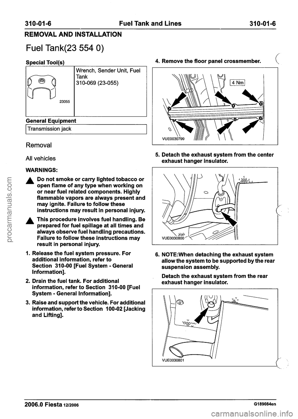
4. Remove the floor panel crossmember. (
5. Detach the exhaust system from the center
exhaust hanger insulator.
result in personal injury.
I
1. Release the fuel system pressure. For 6. N0TE:When detaching the exhaust system
additional information, refer to
allow the system to be supported by the rear
Section
31 0-00 [Fuel System - General
suspension assembly.
Information].
. Detach the exhaust system from the rear 2. Drain the fuel tank. For additional
exhaust hanger insulator.
information, refer to Section
31 0-00 [Fuel
System
- General Information].
3. Raise and support the vehicle. For additional
information, refer to Section
100-02 [Jacking
and Lifting].
2006.0 Fiesta 1212006 GI 89084en
procarmanuals.com