2007 FORD FIESTA warning
[x] Cancel search: warningPage 991 of 1226

Automatic TransmissionlTransaxle -
Vehicles With: 4-Speed Automatic
307-01 -31 Transmission (AW81-40) 307-01 -31
DESCRIPTION AND OPERATION
The transmission control unit determines hill climb
mode or trailer operation from the change in throttle
; valve position supplied by the PCM in relation to
the acceleration of the vehicle.
Depending on the driving resistance, the
transmission control unit chooses between two
gearshift maps which have been specially
programmed for this purpose and in which the shift
timings are again chosen as a function of the
accelerator pedal position and the vehicle speed..
Hill descent mode
The hill descent mode is used to take better
advantage of engine braking during hill descents.
A 'hill descent' situation is recognised by the
transmission control unit if the vehicle is
accelerating without operation of the accelerator
pedal.
If in addition the brake is also depressed then the
transmission control unit automatically shifts back
from 4th into 3rd gear.
( ' Cold start mode
In order to reach operating temperature as quickly
as possible under low ambient temperatures,
gearshifts into 4th gear and engagement of the
torque converter clutch (TCC) are suppressed if
one of the following conditions is met:
Transmission fluid temperature below +20 "C
Coolant temperature below - 40°C
The following are actuated: SSA shift solenoid valve,
SSB shift solenoid valve,
Shift solenoid valve, TCC.
Overheating protection mode
The overheating protection mode serves to protect
the transmission against overheating and the
serious damage that this can cause.
If the transmission fluid temperature reaches a
temperature of around 135
"C, the transmission
control employs a shift pattern designed to prevent
a further increase in the transmission fluid
temperature. When
the transmission fluid temperature drops
back below approx. 125
"C, the transmission
control exits the overheating protection mode.
The MIL warning lamp is actuated by the
transmission control unit if the transmission fluid
temperature reaches approximately 140
"C.
The MIL warning lamp goes out again when the
transmission fluid temperature drops back to below
around 130
"C.
Main line pressure control
In order to ensure the highest possible efficiency
of the automatic transmission and to limit the power
losses from the fluid pump, the main line pressure
is adapted accordingly by the main regulating valve
as a function of the accelerator pedal position
(driver torque demand) and the selector lever
position.
This is influenced by the following variables:
Accelerator pedal position and actuation
Selector lever position
The following are actuated:
Main 'regulating valve
Engagement of the TCC
The TCC is engaged in 3rd and 4th gear depending
on the current driving situation.
Engagement is controlled in accordance with the
shift map stored in the control unit.
This is influenced by the following variables:
Accelerator pedal position and actuation,
Vehicle speed,
Selector lever position,
Transmission fluid temperature,
Coolant temperature.
The following are actuated:
Shift solenoid valve, TCC.
Torque reduction during gearshifts
In order to improve the quality of gearshifts and to
avoid gearshift judder, the engine torque is reduced
by the PCM in response to a request from the
transmission control unit during gearshifts.
The engine torque is also reduced during
engagement and disengagement of the TCC.
2006.0 Fiesta 1212006 G380530en
procarmanuals.com
Page 995 of 1226

Automatic Transmission/Transaxle -
Vehicles With: 4Speed Automatic
307-01 -35 Transmission (AW81-40) 307-01 -35
DESCRIPTION AND OPERATION
Engine speed
1 The engine speed is detected by the crankshaft
position (CKP) sensor and passed on to the PCM.
The engine speed is transmitted from the PCM via
the CAN
databus to the transmission control unit.
The transmission control unit uses this signal for:
Torque reduction during gearshifts,
Pressure control during gearshifts.
Engine load
The PCM determines a load signal which is
transmitted via the CAN
databus to the
transmission control unit.
The transmission control unit uses this signal for:
Torque reduction during gearshifts,
Pressure control during gearshifts,
Shift timing adaptation during upshifts,
Shift timing adaptation during shifts from 3rd to
4th gear,
Hill climb mode,
( ' Hill descent mode. ' ,
Torque reduction request signal
Before performing a gearshift, the transmission
control unit sends a signal via the CAN
databus to
the PCM requesting a torque reduction.
The PCM then reduces the engine torque, ensuring
that the gearshift is as smooth and judder-free as
possible.
Brake signal
The PCM receives a signal from the stoplamp
switch when the brake pedal is depressed.
This signal is transmitted via the CAN
databus to
the transmission control unit.
The transmission control unit uses this signal for:
Gearshift control,
Engagement of the TCC
Accelerator pedal position
The PCM receives the current accelerator pedal
position signal from the Accelerator Pedal Position
(APP) sensor.
This signal is transmitted via the CAN
databus to
the transmission control unit.
The transmission control unit uses this signal for:
Controlling the main line pressure,
Gearshift control,
Engagement of the TCC,
Shift timing adaptation during upshifts,
Shift timing adaptation during shifts from 3rd to
4th gear,
Shift timing adaptation during shifts from 4th to
3rd gear,
Avoidance of gearshift judder during
engagement of a transmission range,
Torque reduction when pulling away.
Coolant temperature
The coolant temperature is detected by the Engine
Coolant Temperature (ECT) sensor and passed
on to the PCM.
This signal is transmitted via the CAN
databus to
the transmission control unit.
The transmission control unit uses this signal for:
Cold start mode,
Engagement of the TCC
Selector lever position
The transmission control unit transmits the selector
lever position to the instrument cluster.
The instrument cluster uses the signal to send a
request for a warning tone to the GEM when the
selector lever is not in position "P" and the driver's
door is opened.
-
2006.0 Fiesta 1212006 G380530en
procarmanuals.com
Page 996 of 1226

Automatic Transmission/Transaxle -
Vehicles With: 4-Speed Automatic
307-01 -36 Transmission (AW81-40) 307-01 -36
DESCRIPTION AND OPERATION
Actuation of the MIL warning lamp Warning tone request
The information required to actuate the
MIL The
driver's door is open.
warning lamp is sent the transmission control The instrument cluster passes on the warning tone unit to the instrument cluster.
request to the GEM. The GEM generates the
warning tone.
I I I
Actuation of the overdrive indicator lamp
I
The overdrive indicator lamp is located on the
instrument panel.
The MIL warning lamp
is actuated by the The transmission control unit sends
a warning tone
instrument cluster if there are serious faults in the request
to the instrument cluster if the following
transmission control or if the transmission fluid conditions are
met:
temperature is excessively high.
The selector lever is not in position "P",
The information required to actuate the overdrive
indicator lamp is sent from the transmission control
unit when the overdrive switch on the selector lever
is pressed.
2006.0 Fiesta 1u2oos G380530en
procarmanuals.com
Page 1000 of 1226

Automatic Transmission/Transaxle -
Vehicles With: 4-Speed Automatic
307-01 -40 Transmission (AW81-40)
307-01 -40
DESCRIPTION AND
OPEMION
Driver's side door ajar switch
The door ajar switch is located in the door lock on
the driver's side.
When the door is closed a ground connection is
signalled to the transmission control unit.
When the door is opened this ground connection
is interrupted.
The transmission control unit uses the signal from
the driver's side door ajar switch to warn the driver
if the selector lever is not in position
"P" and the
driver's door is open.
In this case the transmission control unit transmits
the warning tone request via the CAN
databus to
the instrument cluster.
The instrument cluster passes this request on to
the GEM, which then generates a warning tone.
Consequences of signal failure:
no warning tone request.
Actuators
Main regulating valve
Item Description
I 1 I Main regulating valve I
The main regulating valve is a proportional valve
which converts the applied electric current into a
proportional hydraulic pressure.
The currentless state corresponds to maximum
pressure.
/
The main regulating valve is used to determine the
main line pressure and therefore the actuating
pressure for the clutches and brakes.
Consequences of signal failure:
hydraulic emergency running mode.
SSA and SSB shift solenoid valves
Item Description
2006.0 Fiesta 1212006 G380530en
1
2
SSA
SSB
(- t..
procarmanuals.com
Page 1008 of 1226

Automatic TransmissionlTransaxle -
Vehicles With: 4-Speed Automatic
307-01 -48 Transmission (AW81-40) 307-01 -48
DIAGNOSIS AND TESTING
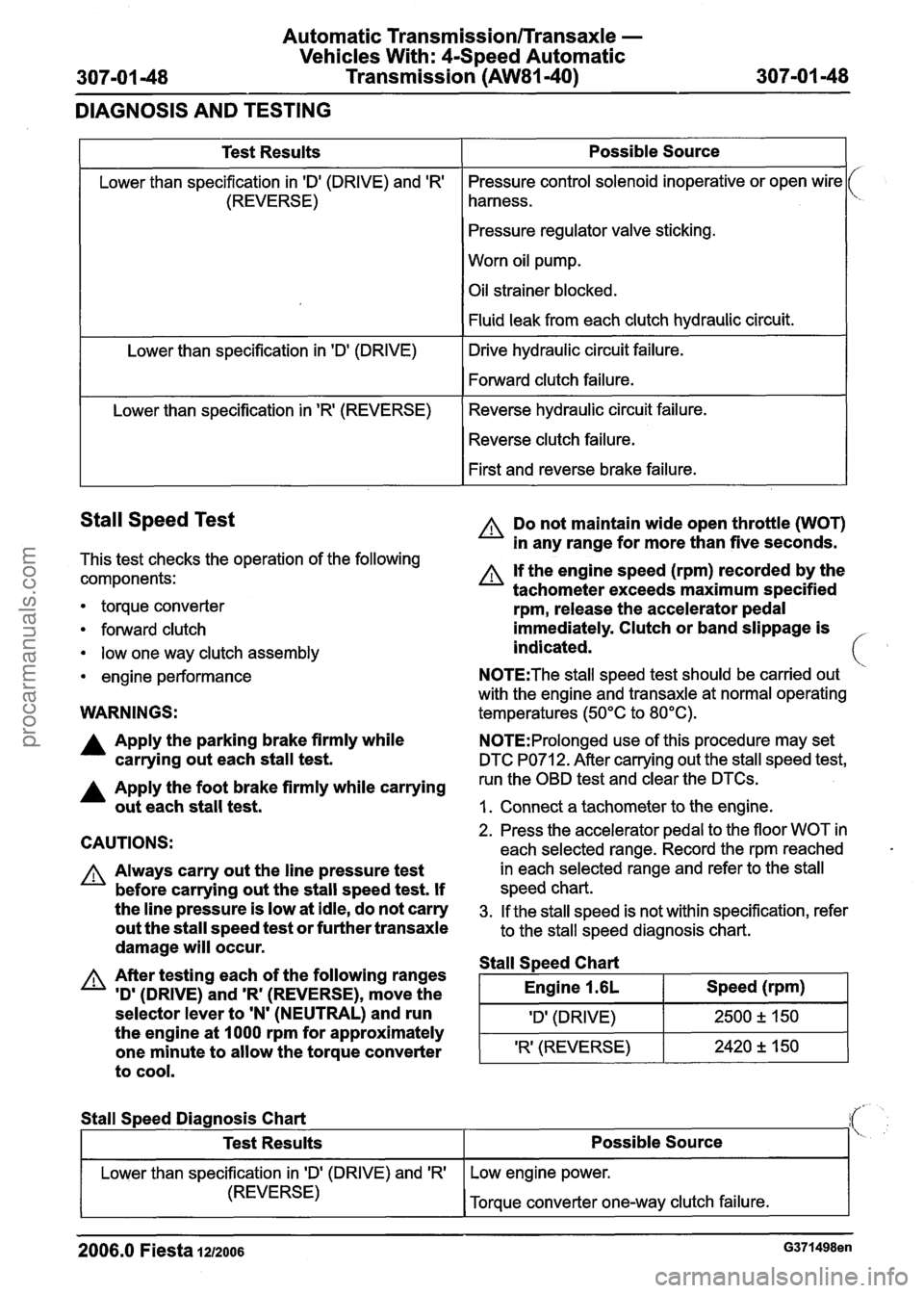
Stall Speed Test
This test checks the operation of the following
components:
1
Test Results
Lower than specification in 'Dl (DRIVE) and 'R'
(REVERSE)
Lower than specification in
'Dl (DRIVE)
Lower than specification in
'R' (REVERSE)
torque converter
forward clutch
low one way clutch assembly
engine performance
Possible Source
Pressure control solenoid inoperative or open wire
harness.
Pressure regulator valve sticking.
Worn oil pump.
Oil strainer blocked.
Fluid leak from each clutch hydraulic circuit.
Drive hydraulic circuit failure.
Forward clutch failure.
Reverse hydraulic circuit failure. Reverse clutch failure.
First and reverse brake failure.
WARNINGS:
A Do not maintain wide open throttle (WOT)
in any range for more than five seconds.
A If the engine speed (rpm) recorded by the
tachometer exceeds maximum specified
rpm, release the accelerator pedal
immediately. Clutch or band slippage is
indicated.
N0TE:The stall speed test should be carried out
with the engine and transaxle at normal operating
temperatures (50°C to 80°C).
A Apply the parking brake firmly while N0TE:Prolonged use of this procedure may set
carrying out each stall test. DTC PO71 2. After carrying out the stall speed test,
A Apply the foot brake firmly while carrying run the OBD test and clear the DTCs.
out each stall test. I. Connect a tachometer to the engine.
CAUTIONS:
A Always carry out the line pressure test
before carrying out the stall speed test. If
the line pressure is low at idle, do not carry
out the stall speed test or further transaxle
damage will occur.
A After testing each of the following ranges
'D'
(DRIVE) and 'R' (REVERSE), move the
selector lever to
'N' (NEUTRAL) and run
the engine at 1000 rpm for approximately
one minute to allow the torque converter
to cool.
2. Press the accelerator pedal to the floor WOT in
each selected range. Record the rpm reached
in each selected range and refer to the stall
speed chart.
3. If the stall speed is not within specification, refer
to the stall speed diagnosis chart.
Stall S~eed Chart
I Engine 1.6L I Speed (rpm) I
I 'Dl (DRIVE) I 2500 2 150 1
'R' (REVERSE) 2420 +, 150 -
Stall
Speed Diagnosis Chart
2006.0 Fiesta 1212006 G371498en
Test Results
Lower than specification in ID' (DRIVE) and 'R'
(REVERSE)
Possible Source
Low engine power.
Torque converter one-way clutch failure.
procarmanuals.com
Page 1011 of 1226

Automatic Transmission/Transaxle -
Vehicles With: 4-Speed Automatic
307-01 -51 Transmission (AW81-40) 307-01 -51 -
GENERAL PROCEDURES
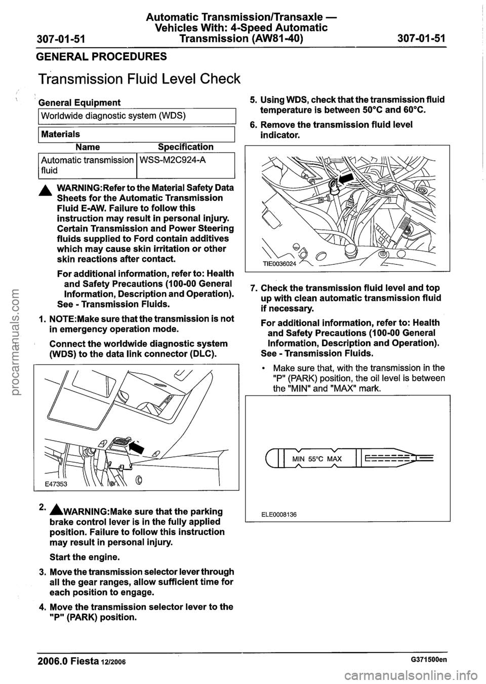
~ransmission Fluid Level Check
( I General Equipment 5. Using WDS, check that the transmission fluid
Worldwide diagnostic system (WDS) temperature is between 50°C and 60°C.
1 6. Remove the transmission fluid level
Materials
A WARN1NG:Refer to the Material Safety Data
Sheets for the Automatic Transmission
Fluid
E-AW. Failure to follow this
instruction may result in personal injury.
Certain Transmission and Power Steering
fluids supplied to Ford contain additives
which may cause skin irritation or other
skin reactions after contact.
For additional information, refer to: Health
and Safety Precautions (1 00-00 General
Information, Description and Operation).
See
- Transmission Fluids.
1. N0TE:Make sure that the transmission is not
in emergency operation mode.
Connect the worldwide diagnostic system
(WDS) to the data link connector (DLC). indicator.
Automatic transmission
lfluid
*' AWARNING:M~~~ sure that
the parking
brake control lever is in the fully applied
position. Failure to follow this instruction
may result in personal injury.
Name
Specification
WSS-M2C924-A
Start the engine.
3. Move the transmission selector lever through
all the gear ranges, allow sufficient time for
each position to engage.
4. Move the transmission selector lever to the
"P" (PARK) position. 7.
Check the transmission fluid level and top
up with clean automatic transmission fluid
if necessary.
For additional information, refer to: Health
and Safety Precautions (1 00-00 General
Information, Description and Operation).
See
- Transmission Fluids.
Make sure that, with the transmission in the
"P" (PARK) position, the oil level is between
the "MIN" and "MAX" mark.
v v
MIN 55°C MAX A A
ELE0008136
2006.0 Fiesta 1212006 G371500en
procarmanuals.com
Page 1013 of 1226

Automatic Transmission/Transaxle -
Vehicles With: 4-Speed Automatic
307-01 -53 Transmission (AW81-40)
307-01 -53
GENERAL PROCEDURES
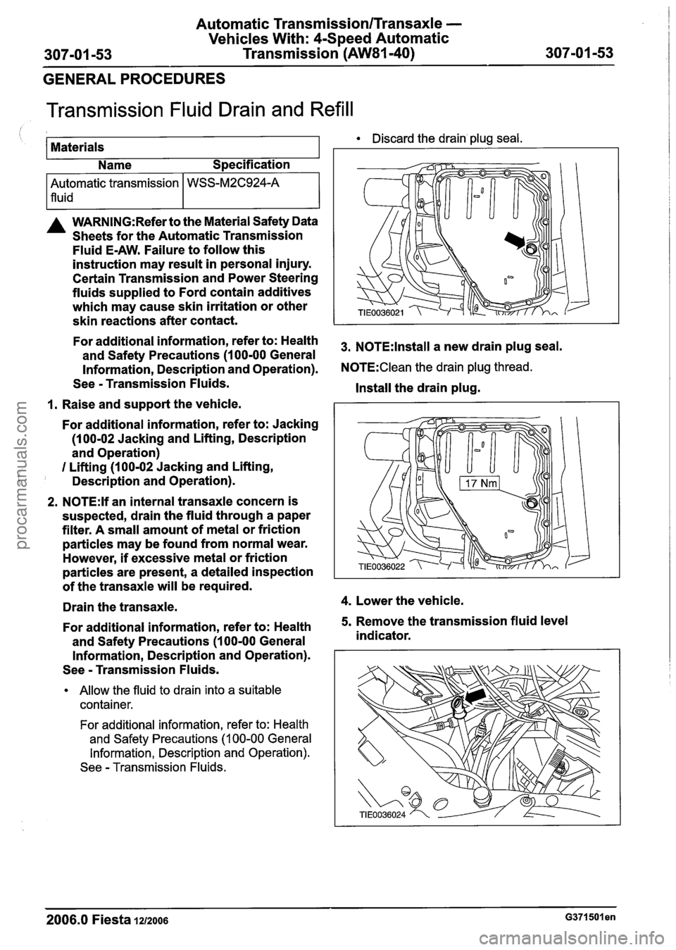
Transmission Fluid Drain and Refill
I I Name Specification
Discard the drain plug seal.
1 Materials
--
A WARNING:Refer to the Material Safety Data
Sheets for the Automatic Transmission
Fluid
E-AW. Failure to follow this
instruction may result in personal injury.
Certain Transmission and Power Steering
fluids supplied to Ford contain additives
which may cause skin irritation or other
skin reactions after contact.
I I
Automatic transmission
lfluid-
For additional information, refer to: Health 3, NOTE:lnstall a new drain plug seal. and Safety Precautions (1 00-00 General
Information, Description and Operation).
N0TE:Clean the drain plug thread.
See - Transmission Fluids.
Install the drain plug.
1. Raise and support the vehicle.
WSS-M2C924-A
For additional information, refer to: Jacking
(1 00-02 Jacking and Lifting, Description
and Operation)
I Lifting (100-02 Jacking and Lifting,
Description and Operation).
2. N0TE:lf an internal transaxle concern is
suspected, drain the fluid through a paper
filter. A small amount of metal or friction
particles may be found from normal wear.
However,
if excessive metal or friction
particles are present, a detailed inspection
of the transaxle will be required.
Drain the transaxle.
4. Lower the vehicle.
For additional information, refer to: Health
5. Remove the transmission fluid level
and Safety Precautions
(1 00-00 General indicator.
Information, Description and Operation).
See
- Transmission Fluids.
Allow the fluid to drain into a suitable
container.
For additional information, refer to: Health
and Safety Precautions
(1 00-00 General
Information, Description and Operation).
See
- Transmission Fluids.
2006.0 Fiesta 1212006 ~371501 en
procarmanuals.com
Page 1019 of 1226

Automatic Transmission/Transaxle -
Vehicles With: 4-Speed Automatic
307-01 -59 Transmission (AW81-40) 307101 -59
IN-VEHICLE REPAIR
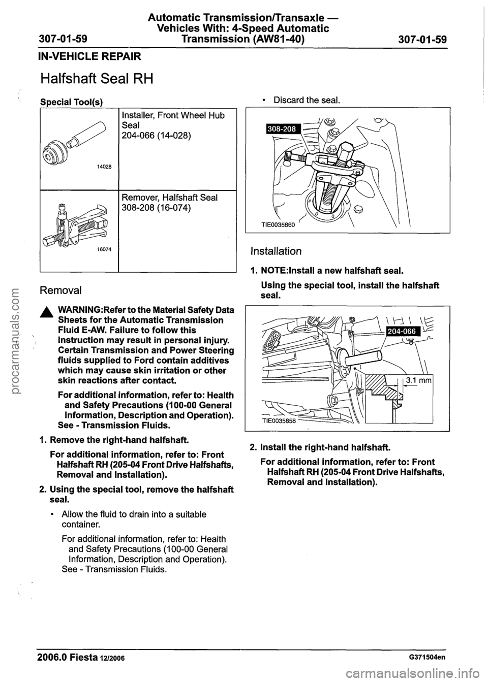
Halfshaft Seal RH
Special Tool@) Discard the seal.
Installer, Front Wheel Hub
Seal
204-066
(1 4-028)
A WARNING:Refer to the Material Safety Data
Sheets for the Automatic Transmission
Fluid E-AW. Failure to follow this
( instruction may result in personal injury. ' , Certain Transmission and Power Steering
fluids supplied to Ford contain additives
which may cause skin irritation or other
skin reactions after contact.
For additional information, refer to: Health
and Safety Precautions (100-00 General
Information, Description and Operation).
See
- Transmission Fluids.
Remover, Halfshaft Seal
308-208
(1 6-074)
1. Remove the right-hand halfshaft. 2. Install the right-hand halfshaft.
For additional information, refer to: Front
Halfshaft
RH (205-04 Front Drive Halfshafts, For
additional information, refer to: Front
Removal and Installation). Halfshaft
RH (205-04 Front Drive Halfshafts,
Removal and lnstallation).
2. Using the special tool, remove the halfshaft
seal.
lnstallation
1. N0TE:lnstall a new halfshaft seal.
Allow the fluid to drain into a suitable
container.
Removal Using the special tool, install the halfshaft
seal.
For additional information, refer to: Health
and Safety Precautions
(1 00-00 General
Information, Description and Operation).
See
- Transmission Fluids.
2006.0 Fiesta 1212006 G371504en
procarmanuals.com