Page 105 of 128

EPA window sticker
Every new vehicle should have the EPA window sticker. Contact your
authorized dealer if the window sticker is not supplied with your vehicle.
The EPA window sticker should be your guide for the fuel economy
comparisons with other vehicles.
It is important to note the box in the lower left corner of the window
sticker. These numbers represent the Range of MPG (L/100 km)
expected on the vehicle under optimum conditions. Your fuel economy
may vary depending upon the method of operation and conditions.
NOTE:Vehicles over 8,500 GVW (Gross Vehicle Weight) will not have
fuel economy information printed on the EPA window sticker.
EMISSION CONTROL SYSTEM
Your vehicle is equipped with various emission control components and a
catalytic converter which will enable your vehicle to comply with applicable
exhaust emission standards. To make sure that the catalytic converter and
other emission control components continue to work properly:
•Use only the specified fuel listed.
•Avoid running out of fuel.
•Do not turn off the ignition while your vehicle is moving, especially at
high speeds.
•Have the items listed inscheduled maintenance information
performed according to the specified schedule.
The scheduled maintenance items listed inscheduled maintenance
informationare essential to the life and performance of your vehicle
and to its emissions system.
If other than Ford, Motorcraft or Ford-authorized parts are used for
maintenance replacements or for service of components affecting
emission control, such non-Ford parts should be equivalent to genuine
Ford Motor Company parts in performance and durability.
Do not park, idle, or drive your vehicle in dry grass or other dry
ground cover. The emission system heats up the engine
compartment and exhaust system, which can start a fire.
Illumination of theService engine soonlight, charging system warning
light or the temperature warning light, fluid leaks, strange odors, smoke
or loss of engine power, could indicate that the emission control system
is not working properly.
2007 Motorhome(mot)
Supplement
USA(fus)
Maintenance and Specifications
105
Page 106 of 128

An improperly operating or damaged exhaust system may allow exhaust
to enter the vehicle. Have a damaged or improperly operating exhaust
system inspected and repaired immediately.
Exhaust leaks may result in entry of harmful and potentially
lethal fumes into the passenger compartment.
Do not make any unauthorized changes to your vehicle or engine. By
law, vehicle owners and anyone who manufactures, repairs, services,
sells, leases, trades vehicles, or supervises a fleet of vehicles are not
permitted to intentionally remove an emission control device or prevent
it from working. Information about your vehicle’s emission system is on
the Vehicle Emission Control Information Decal located on or near the
engine. This decal identifies engine displacement and gives some tune up
specifications.
Please consult yourWarranty Guidefor complete emission warranty
information.
Readiness for Inspection/Maintenance (I/M) testing
Some state/provincial and local governments may have
Inspection/Maintenance (I/M) programs to inspect the emission control
equipment on your vehicle. Failure to pass this inspection could prevent
you from getting a vehicle registration. Your vehicle may not pass the I/M
test if the
indicator is on or not working properly (bulb is burned
out), or if the OBD-II system has determined that some of the emission
control systems have not been properly checked. In this case, the vehicle
is considered not ready for I/M testing.
If the
indicator is on or the bulb does not work, the vehicle may
need to be serviced. Refer to the On board diagnostics (OBD-II)
description in this chapter.
If the vehicle’s engine or transmission has just been serviced, or the
battery has recently run down or been replaced, the OBD-II system may
indicate that the vehicle is not ready for I/M testing. To determine if the
vehicle is ready for I/M testing, turn the ignition key to the ON position
for 15 seconds without cranking the engine. If the
indicator blinks
eight times, it means that the vehicle is not ready for I/M testing; if
the
indicator stays on solid, it means that the vehicle is ready for
I/M testing.
2007 Motorhome(mot)
Supplement
USA(fus)
Maintenance and Specifications
106
Page 107 of 128

The OBD-II system is designed to check the emission control system
during normal driving. A complete check may take several days. If the
vehicle is not ready for I/M testing, the following driving cycle consisting
of mixed city and highway driving may be performed:
15 minutes of steady driving on an expressway/highway followed by 20
minutes of stop-and-go driving with at least four 30 second idle periods.
Allow the vehicle to sit for at least eight hours without starting the
engine. Then, start the engine and complete the above driving cycle. The
engine must warm up to its normal operating temperature. Once started,
do not turn off the engine until the above driving cycle is complete. If
the vehicle is still not ready for I/M testing, the above driving cycle will
have to be repeated.
On board diagnostics (OBD-II)
Your vehicle is equipped with a computer that monitors the engine’s
emission control system. This system is commonly known as the On Board
Diagnostics System (OBD-II). The OBD-II system protects the environment
by ensuring that your vehicle continues to meet government emission
standards. The OBD-II system also assists your authorized dealer in
properly servicing your vehicle. When the
indicator illuminates, the
OBD-II system has detected a malfunction. Temporary malfunctions may
cause the
indicator to illuminate. Examples are:
1. The vehicle has run out of fuel—the engine may misfire or run poorly.
2. Poor fuel quality or water in the fuel—the engine may misfire or run
poorly.
3. The fuel cap may not have been securely tightened. SeeFuel filler
capin this chapter.
4. Driving through deep water – the electrical system may be wet.
These temporary malfunctions can be corrected by filling the fuel tank
with good quality fuel, properly tightening the fuel cap or letting the
electrical system dry out. After three driving cycles without these or any
other temporary malfunctions present, the
indicator should stay off
the next time the engine is started. A driving cycle consists of a cold
engine startup followed by mixed city/highway driving. No additional
vehicle service is required.
If theindicator remains on, have your vehicle serviced at the first
available opportunity. Although some malfunctions detected by the OBD-II
may not have symptoms that are apparent, continued driving with the
indicator on can result in increased emissions, lower fuel economy, reduced
engine and transmission smoothness, and lead to more costly repairs.
2007 Motorhome(mot)
Supplement
USA(fus)
Maintenance and Specifications
107
Page 108 of 128
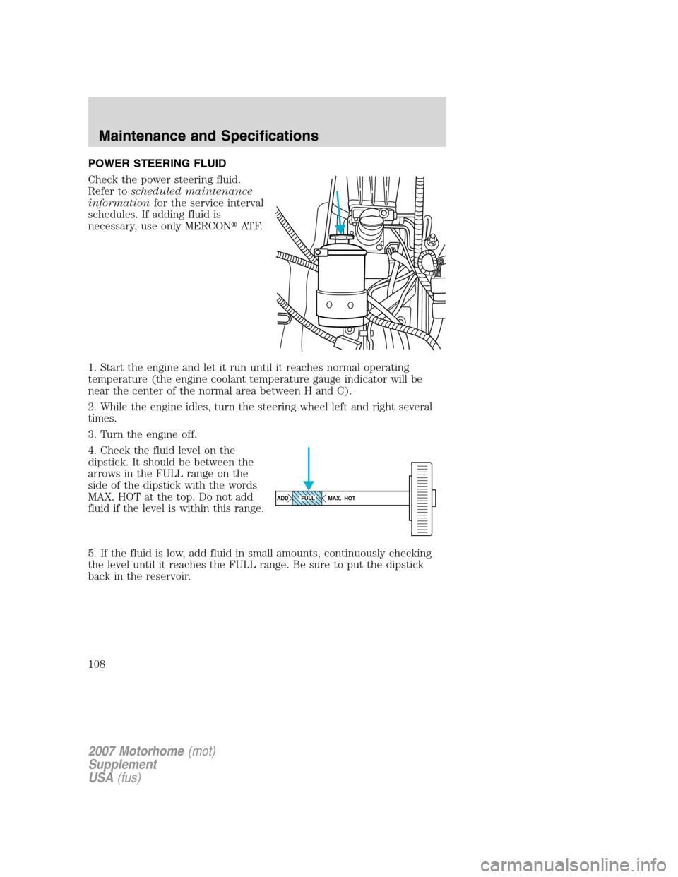
POWER STEERING FLUID
Check the power steering fluid.
Refer toscheduled maintenance
informationfor the service interval
schedules. If adding fluid is
necessary, use only MERCON�AT F.
1. Start the engine and let it run until it reaches normal operating
temperature (the engine coolant temperature gauge indicator will be
near the center of the normal area between H and C).
2. While the engine idles, turn the steering wheel left and right several
times.
3. Turn the engine off.
4. Check the fluid level on the
dipstick. It should be between the
arrows in the FULL range on the
side of the dipstick with the words
MAX. HOT at the top. Do not add
fluid if the level is within this range.
5. If the fluid is low, add fluid in small amounts, continuously checking
the level until it reaches the FULL range. Be sure to put the dipstick
back in the reservoir.
ADD MAX. HOTFULL
2007 Motorhome(mot)
Supplement
USA(fus)
Maintenance and Specifications
108
Page 109 of 128

BRAKE FLUID
Brake fluid should be checked and refilled as needed. Refer to the
scheduled maintenance informationfor the service interval schedules.
•Hydromaxbrake fluid reservoir
Chassis with Gross Vehicle Weight Ratings of 20,500 lb (9,299 kg) and
22,000 lb (9,979 kg) are equipped with Hydromax Brake Booster
Systems and must use Motorcraft Super DOT 4 Motor Vehicle Brake
Fluid or equivalent meeting Ford Specification ESD-M6C57-A. Refer to
Maintenance product specifications and capacitiesin this chapter.
•Hydroboostbrake fluid reservoir
Chassis with Gross Vehicle Weight Ratings of 16,000 lb (7,257 kg) and
18,000 lb (8,165 kg) are equipped with Hydroboost Brake Booster
Systems and must use Motorcraft High Performance DOT 3 Motor
Vehicle Brake Fluid or equivalent meeting Ford Specification
ESA-M6C25-A or WSS-M6C62-A. Refer toMaintenance product
specifications and capacitiesin this chapter..
Note:On Hydromax brake systems a clear gel-like substance in the
hydraulic brake master cylinder reservoir may appear on some vehicles.
This substance is a silicone base lubricant used during assembly of the
master cylinder. It will float on top of the brake hydraulic fluid in the
master cylinder. This condition is normal and in no way affects the
operation of the brake system. It does not require any service.
2007 Motorhome(mot)
Supplement
USA(fus)
Maintenance and Specifications
109
Page 110 of 128

1. Clean the reservoir cap before removal to prevent dirt or water from
entering the reservoir.
2. Visually inspect the fluid level.
3. If necessary, add brake fluid from a clean un-opened container until
the level reaches MAX. Do not fill above this line.
4. Use only a brake fluid listed previously (DOT 3 or Super DOT 4
depending on brake system) and that is certified to meet Ford
specifications. Refer toMaintenance product specifications and
capacitiesin this chapter.
Carefully read cautionary information on product label. For
MEDICAL EMERGENCY INFORMATION contact a physician or
Poison Control Center immediately; on Ford-Motorcraft products call:
1-800-959-3673 (FORD). Failure to follow these instructions may result
in personal injury.
Use of any brake fluid other than that indicated for your brake
system will cause permanent damage.
Do not let the reservoir for the master cylinder run dry. This
may cause the brakes to fail.
Brake system fluid should be replaced on a regular basis to maintain
optimum braking performance, especially under heavy-duty driving
conditions such as frequent steep grades or heavy towing loads. Refer to
scheduled maintenance informationfor the service interval schedules.
2007 Motorhome(mot)
Supplement
USA(fus)
Maintenance and Specifications
110
Page 111 of 128
 or MERCON�
equivalent to the bottom of the filler
plug hole (2) (loca")
Parking Brake Fluid
Check and, if necessary, fill the
parking brake assembly with
Motorcraft MERCON�Multi-Purpose
ATF (XT-2–QDX) or MERCON�
equivalent to the bottom of the filler
plug hole (2) (located on the driver
side of the transmission).
Note:Do not fill the parking brake
through the vent plug (1) (located
on top of the transmission).
TRANSMISSION FLUID
Checking automatic transmission fluid
Refer to yourscheduled maintenance informationfor scheduled
intervals for fluid checks and changes. Your transmission does not
consume fluid. However, the fluid level should be checked if the
transmission is not working properly, i.e., if the transmission slips or
shifts slowly or if you notice some sign of fluid leakage.
Automatic transmission fluid expands when warmed. To obtain an
accurate fluid check, drive the vehicle until it is at normal operating
temperature (approximately 20 miles [30 km]). If your vehicle has been
operated for an extended period at high speeds, in city traffic during hot
weather or pulling a trailer, the vehicle should be turned off for about 30
minutes to allow fluid to cool to normal operating temperature 150°F -
170°F (66°C - 77°C) before checking.
1. Drive the vehicle 20 miles (30 km) or until it reaches normal operating
temperature.
2. Park the vehicle on a level surface and engage the parking brake.
3. With the parking brake engaged and your foot on the brake pedal,
start the engine and move the gearshift lever through all of the gear
ranges. Allow sufficient time for each gear to engage.
2007 Motorhome(mot)
Supplement
USA(fus)
Maintenance and Specifications
111
Page 112 of 128
 and leave the engine running.
5. Remove the dipstick, wiping it clean with a clean, dry lint free rag. If
necessary, refer toIdentifying components in the engi")
4. Latch the gearshift lever in P (Park) and leave the engine running.
5. Remove the dipstick, wiping it clean with a clean, dry lint free rag. If
necessary, refer toIdentifying components in the engine compartment
in this chapter for the location of the dipstick.
6. Install the dipstick making sure it is fully seated in the filler tube.
7. Remove the dipstick and inspect the fluid level. The fluid should be in
the designated area for normal operating temperature or ambient
temperature.
Low fluid level
Do not drive the vehicle if the fluid
level is at the bottom of the dipstick
and the ambient temperature is
above 50°F (10°C).
Correct fluid level
The transmission fluid should be checked at normal operating
temperature 150°F-170°F (66°C-77°C) on a level surface. The normal
operating temperature can be reached after approximately 20 miles
(30 km) of driving.
You can check the fluid without driving if the ambient temperature is
above 50°F (10°C). However, if fluid is added at this time, an overfill
condition could result when the vehicle reaches normal operating
temperature.
The transmission fluid should be in
this range if at normal operating
temperature (150°F-170°F
[66°C-77°C]).
The transmission fluid should be in
this range if at ambient temperature
(50°F-95°F [10°C-35°C]).
High fluid level
Fluid levels above the safe range
may result in transmission failure.
An overfill condition of transmission
fluid may cause shift and/or
engagement concerns and/or possible damage.
High fluid levels can be caused by an overheating condition.
2007 Motorhome(mot)
Supplement
USA(fus)
Maintenance and Specifications
112
 1
1 2
2 3
3 4
4 5
5 6
6 7
7 8
8 9
9 10
10 11
11 12
12 13
13 14
14 15
15 16
16 17
17 18
18 19
19 20
20 21
21 22
22 23
23 24
24 25
25 26
26 27
27 28
28 29
29 30
30 31
31 32
32 33
33 34
34 35
35 36
36 37
37 38
38 39
39 40
40 41
41 42
42 43
43 44
44 45
45 46
46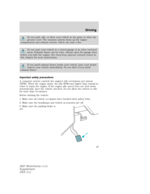 47
47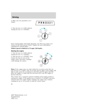 48
48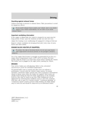 49
49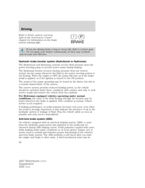 50
50 51
51 52
52 53
53 54
54 55
55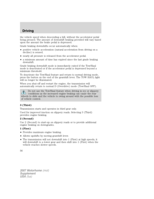 56
56 57
57 58
58 59
59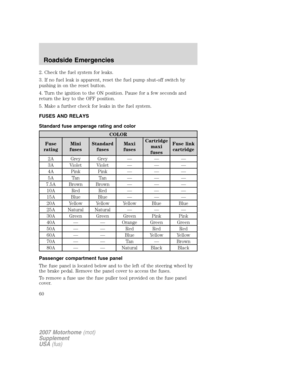 60
60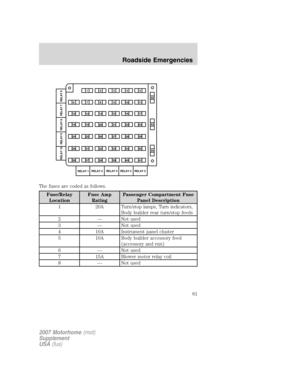 61
61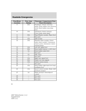 62
62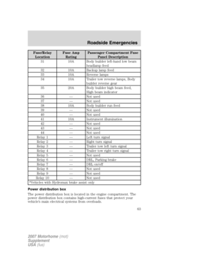 63
63 64
64 65
65 66
66 67
67 68
68 69
69 70
70 71
71 72
72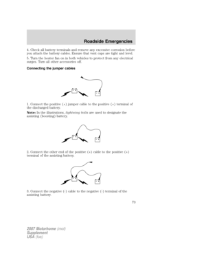 73
73 74
74 75
75 76
76 77
77 78
78 79
79 80
80 81
81 82
82 83
83 84
84 85
85 86
86 87
87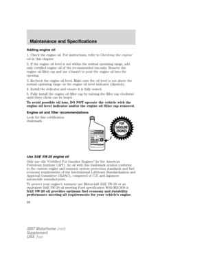 88
88 89
89 90
90 91
91 92
92 93
93 94
94 95
95 96
96 97
97 98
98 99
99 100
100 101
101 102
102 103
103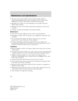 104
104 105
105 106
106 107
107 108
108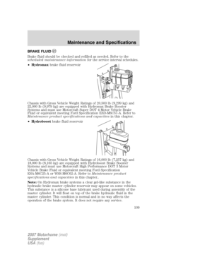 109
109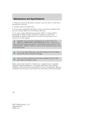 110
110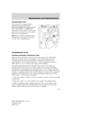 111
111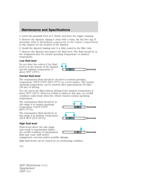 112
112 113
113 114
114 115
115 116
116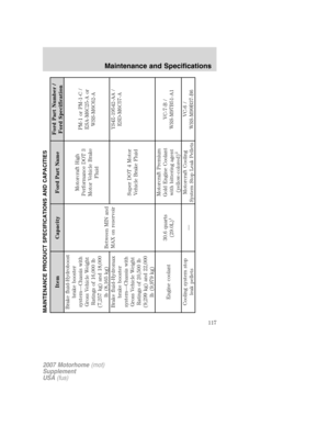 117
117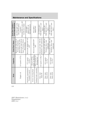 118
118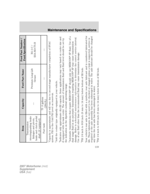 119
119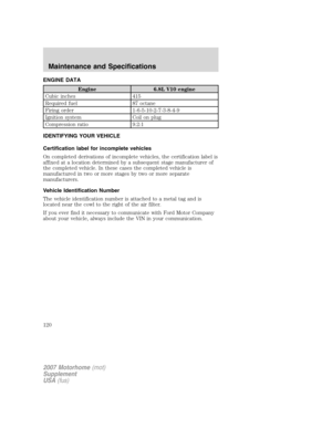 120
120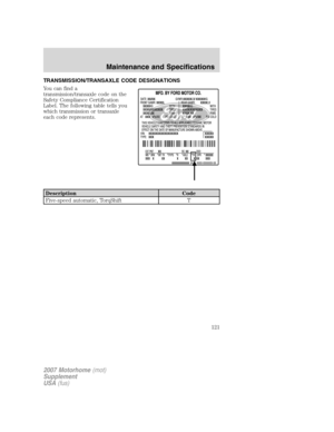 121
121 122
122 123
123 124
124 125
125 126
126 127
127