Page 49 of 218

Once you have released
the lever, check that the
seat is firmly locked in the
runners by trying to move it back
and forth. Failure to lock the seat
in place could result in the seat
moving suddenly and dangerous-
ly.
Adjusting the reclining seat
back
Lift lever E-fig. 50.
48GETTING TO KNOW YOUR VEHICLE
INDIVIDUAL
SETTINGS
DRIVER’S SEAT
Only make adjustments
when the vehicle is sta-
tionary.
Moving the seat backwards or
forwards
Lift the lever A-fig. 50and push the
seat forwards or backwards. You are
in the correct position for driving when
your hands are resting on the steering
wheel rim and your arms are slightly
bent.
fig. 50
F0A0258b
MAIN BEAMS (blue)
The warning light turns on
when the main beams are
turned on.
POSSIBLE PRESENCE OF ICE
ON THE ROAD
(versions with reconfigurable
multifunction display)
This indication starts flashing when
the outside temperature reaches or
falls below 3°C to warn the driver of
the possible presence of ice on the
road.
The display will show the dedicated
message.
LIMITED RANGE
(versions with reconfigurable
multifunction display)
The display will show the dedicated
message to warn the driver that the
cruising range is less than 50 km.
1
Page 51 of 218

50GETTING TO KNOW YOUR VEHICLE
Once you have released
the lever, check that the
seat is firmly locked in the
runners by trying to move it back
and forth. Failure to lock the seat
in place could result in the seat
moving suddenly and dangerous-
ly.
FOLDING FRONT
PASSENGER SEAT
Folding the seat back
Lift lever A-fig. 54to fold the seat
back and obtain a tabletop.Tipping the seat
To tip the seat and make more space
in the passenger compartment pro-
ceed as follows:
– tip the seat as described previous-
ly;
– use lever B-fig. 55to tip the whole
seat forward;
– lock the seat using the special rod
A-fig. 56and fitting it into slot Bon
the seat.
To return the seat to normal posi-
tion, release rod Aand then raise the
seat.
IMPORTANTWhen folded, the
seat shall be anchored by the proper
rod ‘to prevent its violent returning
to original position when accelerating.
fig. 54
F0A0250b
SLIDING PASSENGER SEAT
Adjusting the reclining seat
back
Lift lever A-fig. 52.
Moving the seat backwards or
forwards
Lift lever B-fig. 53and push the seat
backwards or forwards.
B
fig. 53
F0A0198b
Page 53 of 218

The ladder shall only be
tilted with the vehicle sta-
tionary and the door
open.
52GETTING TO KNOW YOUR VEHICLE
You cannot open the
left-hand sliding side door
while refuelling when the
flap is open (see “At the filling
station” in this section).
Versions with two sliding side
doors
Open either of the two sliding side
doors to access the rear seats. ACCESSING
THE REAR SEATS
Versions with one sliding side
door (on passenger side)
From passenger’s side: open the
sliding side door.
From driver’s side:pull handle F-
fig. 59aupwards to tip the seat back.
Once you have let go of the lever,
check that the seat is firmly locked in
the runners by trying to move it back
and forth.In the event of an emer-
gency, you can get out of
the rear seats from the
driver’s side by tilting the driver’s
seat.
EC
D
fig. 58
F0A0187bD
D
E
fig. 59
F0A0199b
Releasing the ladder: press but-
ton E-fig. 59to release the ladder
from the handle D. Reposition the lad-
der in its original position. Tip the seat
by lowering the cushion and lifting the
seat back. Make sure that the seat is
locked.
fig. 59a
F0A0600b
Page 54 of 218

53GETTING TO KNOW YOUR VEHICLE
HEAD RESTRAINTS
Front seats
According to the version, the head
restraints can be:
– fixed fig. 60;
– adjustable in height fig. 61.
To adjust, move the head restraint
upwards or downwards until it clicks.
Make sure it is properly locked in
place.
Fixed head restraints cannot be re-
moved.
fig. 60
F0A0036b
7-seat versions
To access the third row:
– open the side sliding door;
– lower the head restraints (if set in
the normal position of use) (see para-
graph “Head restraints”);
– release lever A-fig. 59band fold
the seat forward onto the cushion;
– raise the whole cushion fig. 59c.
To get out of the vehicle, reverse the
above operations and make sure head
restraints are lowered.
fig. 59b
F0A0403b
fig. 59c
F0A0404b
IMPORTANTIt is forbidden to
travel with the second row seats
tipped and third row seats set in nor-
mal position of use. More particularly,
if the central seat of the second row
is tipped and that of the third row is
set in normal position of use, a buzzer
will sound to indicate the wrong seat
position.
It is absolutely forbidden
to travel with the second
row seats tipped and pas-
sengers seated on the third row
seats (as specified on the seat la-
bel).
Page 68 of 218

67GETTING TO KNOW YOUR VEHICLE
– switch Apressed to the right, ceil-
ing lights Cand Dwill stay on in what-
ever condition.
When the ceiling light is off, switch
Bturns on the following lights:
– map-reading light Cif pressed to
the left;
– map-reading light Dif pressed to
the right.
IMPORTANTMake sure that both
switches are in central position before
getting out of the vehicle. This is en-
sure that the ceiling lights go out when
the doors are closed preventing the
battery from running down.
Timing for getting into the
vehicle
The ceiling lights will come on as fol-
lows:
– for 15 seconds when the front
doors are unlocked;– for 7 seconds when a door is
closed (within the three minutes).
Timing will be stopped when the ig-
nition key is turned to MAR.
Timing for getting out of the
vehicle
The ceiling lights will come on as fol-
lows when the key is removed from
the ignition switch:
– for 3 minutes within two minutes
after stopping the engine;
– for 7 seconds when a door is
closed (within the three minutes).
Timing will be stopped when the
doors are locked.WITH TOGGLE LENS
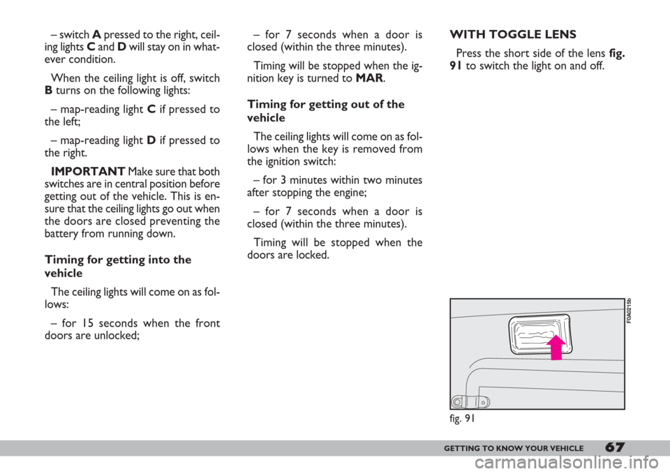
Press the short side of the lens fig.
91to switch the light on and off.
fig. 91
F0A0215b
Page 70 of 218

69GETTING TO KNOW YOUR VEHICLE
The rear fog lights are switched off
either by pressing C or switching on
the main beam headlights or turning
the ignition key to STOP. You will
need to switch the rear foglights back
on, if required, when the dipped beam
headlights and/or front foglights are
switched on or when the engine is
started again.
FUEL CUT-OFF SWITCH
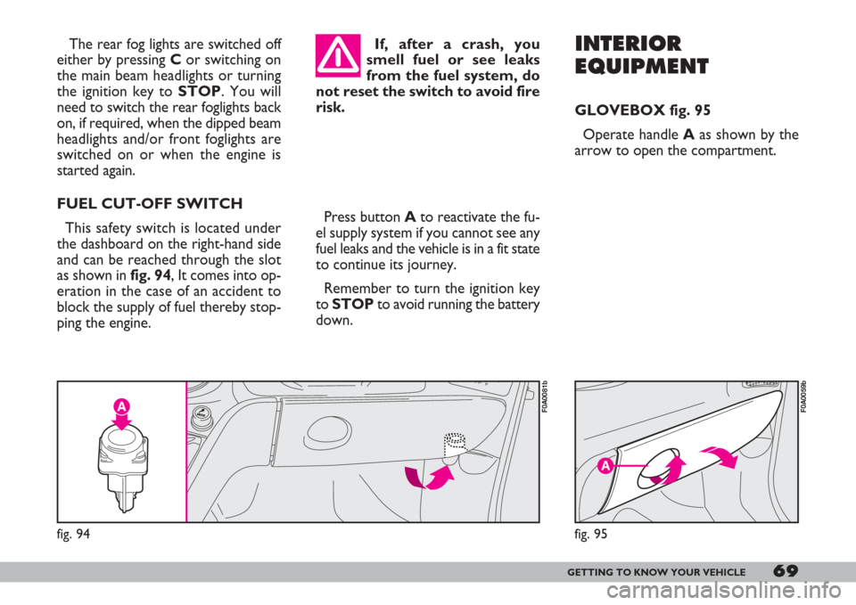
This safety switch is located under
the dashboard on the right-hand side
and can be reached through the slot
as shown in fig. 94, It comes into op-
eration in the case of an accident to
block the supply of fuel thereby stop-
ping the engine.Press button Ato reactivate the fu-
el supply system if you cannot see any
fuel leaks and the vehicle is in a fit state
to continue its journey.
Remember to turn the ignition key
to STOPto avoid running the battery
down.INTERIOR
EQUIPMENT
GLOVEBOX fig. 95
Operate handle Aas shown by the
arrow to open the compartment.
fig. 94
F0A0081b
If, after a crash, you
smell fuel or see leaks
from the fuel system, do
not reset the switch to avoid fire
risk.
A
fig. 95
F0A0059b
Page 74 of 218

73GETTING TO KNOW YOUR VEHICLE
Closing the wing window
Take the mobile crossmember C-
fig. 106back to its original position;
fit the crossmember pin Cin the orig-
inal housing until it clicks.
Pull the wing window in the direction
shown in fig. 105, fitting your hand
in handle B. The wing window is
closed once it clicks.
DC
fig. 106
F0A0071b
Moving the vehicle when
the crossmember is not
fastened in its housing can
cause severe damage to the load
compartment structure. Fur-
thermore, only the bottom of the
rear doors would be locked and
this could damage the hinges.
IMPORTANTArrange the load
evenly along the crossmember and fas-
ten it with ropes or similar.
IMPORTANTNever leave the
crossmember unfastened while the ve-
hicle is moving.
B
fig. 105
F0A0070b
Do not exceed 110 km/h
speed with wing window
open. Risk of (violent)
wing window closing.
The mobile crossmember C-fig. 106
can be tipped down to facilitate load-
ing and unloading long objects.
To tip, hold the crossmember with
your left-hand and move the lever D
with your right-hand in the direction of
the arrow until it clicks.
Lower the crossmember carefully
until it reaches its position. Unload the
vehicle and take the crossmember
back to its original position.
Page 75 of 218
74GETTING TO KNOW YOUR VEHICLE
These operations are allowed for
two minutes after turning the ignition
key from MARto STOPor removed
only if the doors are closed.
AB
fig. 109
F0A0074b
fig. 109a
F0A0510b
Closing by hand from the inside
Front doors: close the door and
press the lever as shown in fig. 108
(LOCK).
ELECTRIC WINDOWS
According to versions, power win-
dow controls can be set on the dash-
board (in central position) fig. 109, or
on driver and passenger door panels
fig. 109a. They only work with igni-
tion key at MAR.
A- to open/close the front left-hand
window;
B- to open/close the front right-
hand window.
fig. 108
F0A0514b
DOORS
FRONT DOORS
Opening by hand from
the outside
Front doors: turn the key to 2-fig.
107and pull the handle.
Locking by hand from
the outside
Front doors: close the door and turn
the key to 1-fig. 107.
Opening by hand from
the inside
Front doors: pull the lever.
2
1
fig. 107
F0A0072b