2007 DODGE SPRINTER warning
[x] Cancel search: warningPage 73 of 393

72 Controls in detailSeats
3
Positioning the seat cushion
\1Fold the seat cushion back.
\1Slide the seat cushion under the back-
rest and into rear anchorage2.
\1Fold the seat cushion down.
\1Press the front of the seat cushion
down until it engages in front
anchorage1.
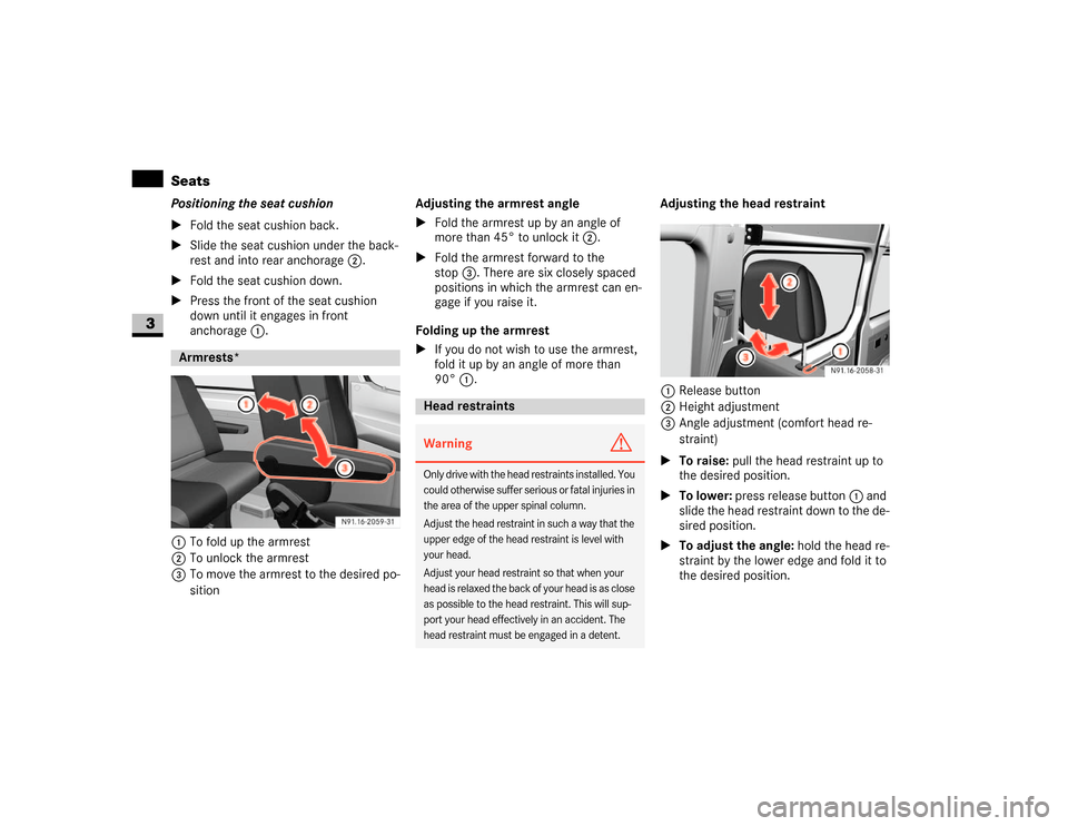
1To fold up the armrest
2To unlock the armrest
3To move the armrest to the desired po-
sitionAdjusting the armrest angle
\1Fold the armrest up by an angle of
more than 45° to unlock it2.
\1Fold the armrest forward to the
stop3. There are six closely spaced
positions in which the armrest can en-
gage if you raise it.
Folding up the armrest
\1If you do not wish to use the armrest,
fold it up by an angle of more than
90°1.Adjusting the head restraint
1Release button
2Height adjustment
3Angle adjustment (comfort head re-
straint)
\1To raise: pull the head restraint up to
the desired position.
\1To lower: press release button1 and
slide the head restraint down to the de-
sired position.
\1To adjust the angle: hold the head re-
straint by the lower edge and fold it to
the desired position.Armrests*
Head restraints Warning
G
Only drive with the head restraints installed. You
could otherwise suffer serious or fatal injuries in
the area of the upper spinal column.
Adjust the head restraint in such a way that the
upper edge of the head restraint is level with
your head.
Adjust your head restraint so that when your
head is relaxed the back of your head is as close
as possible to the head restraint. This will sup-
port your head effectively in an accident. The
head restraint must be engaged in a detent.
Page 75 of 393

74 Controls in detailSeats
3
The folding seat is on the co-driver’s side. Folding seat next to the partition sliding
door1Key for partition sliding door
2Seat cushion\1Remove key1 from partition sliding
door.
\1Fold seat cushion2 down or up.
The seat cushion is held in the relevant
position.Folding seat*
Warning
G
When folding down the seat cushion, make
sure that nobody can become trapped.
The risk of injury to the co-driver is in-
creased in the event of sudden steering
movements or an accident if there is a key
inserted in the partition sliding door lock.
Remove the key from the partition sliding
door before using the folding seat.
Rear bench seatWarning
G
All release levers on the legs of the rear
bench seat must be parallel to the vehicle
floor. A rear bench seat with 2 seats may
only be installed left-sided.
You can obtain information from any autho-
rized Sprinter dealer.
The integrated seat belt can only offer the
degree of protection for which it is designed
if you install the specified rear bench seats
correctly.
Keep the seat bench mounting cups in the
vehicle floor free from dirt and foreign
objects. This is the only way to guarantee
that the locking mechanisms will engage se-
curely.
For reasons of safety, only have seat mount-
ing cups retrofitted at an authorized Sprinter
dealer.
Page 77 of 393

76 Controls in detailSteering wheel adjustment
3
\3 Steering wheel adjustment
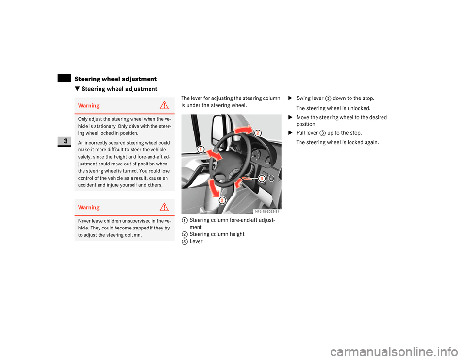
The lever for adjusting the steering column
is under the steering wheel.
1Steering column fore-and-aft adjust-
ment
2Steering column height
3Lever\1Swing lever 3 down to the stop.
The steering wheel is unlocked.
\1Move the steering wheel to the desired
position.
\1Pull lever3 up to the stop.
The steering wheel is locked again.
Warning
G
Only adjust the steering wheel when the ve-
hicle is stationary. Only drive with the steer-
ing wheel locked in position.
An incorrectly secured steering wheel could
make it more difficult to steer the vehicle
safely, since the height and fore-and-aft ad-
justment could move out of position when
the steering wheel is turned. You could lose
control of the vehicle as a result, cause an
accident and injure yourself and others.Warning
G
Never leave children unsupervised in the ve-
hicle. They could become trapped if they try
to adjust the steering column.
N46.15-2032-31
Page 79 of 393

78 Controls in detailLighting
3
\1Turn key to position1 in ignition lock
(\2page 67).
\1Turn light switch to B.
\1Press combination switch forward 1.
The indicator lampA in the instru-
ment cluster lights up.
Headlamp flasher
\1Turn key to position1 in ignition lock
(\2page 67).
\1Pull combination switch briefly in
direction2.
Constant headlamp mode*
On vehicles with steering wheel buttons,
you can set constant headlamp mode
(\2page 102). This does not apply to coun-
tries in which there is a legal requirement
to use constant headlamp mode.\1Turn light switch to M.
The low-beam headlamps, parking
lamps and license plate lamp are
switched on when the engine is
running.
TheB indicator lamp in the instru-
ment cluster lights up.
Automatic headlamp control*
The parking lamps, low-beam headlamps
and license plate lamp are switched on au-
tomatically when the brightness of ambi-
ent light falls below a predetermined level.\1Turn light switch toU.
The parking lamps are switched on / off
automatically when the key is in posi-
tion 1 (\2page 67) in the ignition lock.
The parking lamps, low-beam head-
lamps and license plate lamp are
switched on / off automatically when
the engine is running, depending on the
ambient light conditions.
Only use manual headlamp mode when
you are driving in countries where driving
with the low-beam headlamps switched on
is required by law.
\1In this case, turn the light switch to
B.
Warning
G
If the light switch is atU:
\4the headlamps could switch off tempo-
rarily due to extreme glare, e.g. from on-
coming traffic
\4the lights do not switch on automatically
in foggy conditions
Set the light switch to B. Otherwise you
are endangering yourself and others.
If it is dark, only turn the light switch from
U toB when the vehicle is stationary.
You could otherwise cause an accident if the
headlamps were to switch off briefly.
Automatic headlamp mode is only a driving
aid. You are responsible for the vehicle’s
lighting at all times.
Page 81 of 393

80 Controls in detailLighting
3
\1Push combination switch up1 or
down 2 until it engages.
The combination switch moves back
automatically if the steering wheel is
turned sufficiently.The hazard warning lamps still operate if
the ignition is switched off and the key is
removed.
The switch is located on the center con-
sole.
1Hazard warning lamps switch
\1To switch on: press the switch.
All turn signals and the switch flash.
\1To switch off: press the switch again.Standard front interior lighting
1To switch on the interior lighting
2Automatic control
3To switch off the interior lighting
iTo indicate minor directional changes
such as changing lanes, press the com-
bination switch only to point of resis-
tance and release. The corresponding
turn signals will flash three times.
Hazard warning lampsWarning
G
The rear lamps are concealed when the rear
doors are opened 90° (detent position).
N54.25-2919-31
The vehicle is then not sufficiently safe-
guarded at the rear and may only be seen by
other road users when they are close to the
vehicle. This could lead to an accident.
Make sure, therefore, that the vehicle is
safeguarded at the rear in accordance with
national legal requirements, e.g. with a
warning triangle.Front interior lighting
Page 84 of 393

83 Controls in detail
Lighting
3
Load compartment motion detector*
On panel vans equipped with a motion de-
tector in the load compartment, the rear
interior lighting may also switch on if mo-
tion is detected.The rear interior lighting can be switched
on by the motion detector with a delay of
no more than 4 seconds if:
\4the switch on the rear interior lamp
(\2page 82) is set to “automatic con-
trol”
\4the vehicle is stationary, the handbrake
is applied and the service brake is not
applied
or
\4the selector lever is in position P and
the service brake is not applied
\4the vehicle has not been locked from
the outside using the key
iThe rear interior lamps switch off auto-
matically after 20 minutes, even if the
switches on the rear interior lamps
(\2page 82) are in the On position 1.
If you wish to reactivate the rear interi-
or lamps, you must:
\4open a door
\4switch on the ignition again
\4set the rear interior lighting master
control switch to position2 again.
Warning
G
Motion detectors work with invisible infra-
red beams emitted by LEDs (Light Emitting
Diodes).
Do not view invisible infrared radiation, laser
class 1M, directly using optical instruments.
Your eyes could otherwise be injured.iIf the motion detector detects move-
ment in the load compartment when
the vehicle is stationary, the rear interi-
or lighting switches on for approxi-
mately 2 minutes. If new movements
are detected, the duration resumes
from the beginning and the rear interior
lighting remains switched on.
iThe motion detector switches off auto-
matically if no change is detected in the
vehicle for several hours, e.g. door
opened, ignition key turned, etc.
This prevents the battery from dis-
charging.
Page 86 of 393

85 Controls in detail
Lighting
3
With the lights switched on, you can adjust
the brightness of the instrument lighting
using the and buttons.
\1Brighter: press the button.
\1Dimmer: press the button.The red band in the tachometer indicates
the engine’s overrevving range.
To protect the engine, the fuel supply is in-
terrupted when the red band is reached.
Warning
G
No messages can be displayed if the instru-
ment cluster and / or the display is malfunc-
tioning.
You will not then be able to see information
about the vehicle status, such as speed and
outside temperature, warning and indicator
lamps, malfunction and warning messages
or the malfunction of systems. Handling
characteristics may be affected.
Contact a qualified specialist workshop im-
mediately which has the necessary special-
ist knowledge and tools to carry out the
work required.
The manufacturer recommends that you use
an authorized Sprinter Dealer for this pur-
pose. In particular, work relevant to safety
or on safety-related systems must be car-
ried out at a qualified specialist workshop.
Only use adjustment buttons , , ,
or when traffic conditions permit.
You will otherwise be unable to observe road
and traffic conditions and could cause an ac-
cident.
Do not reach through the steering wheel to
press the adjustment buttons. This will
make the steering wheel much more difficult
to control. Your attention will also be divert-
ed from the road and traffic conditions. This
could cause you to lose control of the vehi-
cle and could lead to an accident.
Do not rest your head or chest on the steer-
ing wheel or dashboard when operating the
adjustment buttons. See the safety precau-
tions for airbags (\2page 31).Instrument lightingiVehicles with automatic headlamp
mode*:
The instrument lighting also adjusts in
line with the automatic headlamp
mode.
Tachometer!
CAUTION
Do not drive in the overrevving range.
Doing so could damage the engine.
Environmental note
H
Avoid high engine speeds. These could in-
crease your vehicle’s fuel consumption un-
necessarily and damage the environment
through increased pollutant emissions.SpeedometeriIn some countries, a signal sounds
when the vehicle reaches the maximum
speed limit, e.g. at 75 mph
(120 km/h).
Page 87 of 393

86 Controls in detailLighting
3
\1Vehicles with steering wheel buttons*:
Make sure that the display is showing
the trip meter (\2page 93).
\1Keep reset button pressed until the
trip meter is set to
0.0
.
Fuel gaugeFuel gauge1
Vehicles without steering wheel
buttons
2
Vehicles with steering wheel but-
tons*
3
Fuel filler flap location indicator
Ö: The fuel filler cap is on the
left-hand side
4
Reserve fuel warning lamp
(\2page 276)
Resetting the trip meter