Page 300 of 393
299 Practical hints
Where will I find...?
5
The warning triangles are behind the driv-
er's seat.
1Warning triangles
\1Remove warning triangles1 from the
brackets upward.The fire extinguisher is secured to the front
of the co-driver’s seat base.
1Fire extinguisher
2Tabs
\1Pull tabs2 upward.
\1Take fire extinguisher1 out of the
bracket.The first-aid kit is located in the storage
compartment in the co-driver’s door.
1Locked
2Unlocked
Turn the two quick-release locks clockwise
to unlock2 and fold out the cover.
Warning triangle and warning lamp
N72.10-2148-31
Fire extinguisheriRead the instructions on the fire extin-
guisher carefully and familiarize your-
self with its operation.
First-aid kit
Page 302 of 393

301 Practical hints
Where will I find...?
5
3Tensioning lever
4Jack
5Vehicle tool kit
\1Remove the vehicle tool kit.
\1Pull tensioning lever3 upward and
unhook the retaining strap of jack4.
\1Remove jack4 upward out of the re-
tainer.If you are replacing the tires on the vehicle,
you may use the spare wheel as a road
wheel provided that:
\4the tires are no more than 6 years old
\4the wheel and tire have the same spec-
ified design as the road wheels
The spare wheel is located in a spare wheel
bracket under the rear of the vehicle.
More information about tire inflation pres-
sures can be found in the "Operation" sec-
tion (\2page 213).Panel van / crewbus
1Cover
2Recess
\1Open the rear doors (\2page 61).
\1Insert a screwdriver into recesses2
and pry off covers1.
\1Using the wheel wrench from the vehi-
cle tool kit (\2page 300), now unscrew
the visible bolts approximately
20 turns counterclockwise.
iPlace the jack into the retainer as
shown when storing it back into place.
Make sure that the jack’s retaining
strap is hooked in and tensioned.
Spare wheel!
CAUTION
Check regularly that the spare wheel is
secured correctly.
Page 303 of 393

302 Practical hintsWhere will I find...?
5
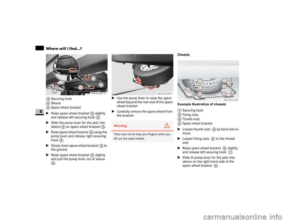
3Securing hook
4Sleeve
5Spare wheel bracket
\1Raise spare wheel bracket5 slightly
and release left securing hook3.
\1Slide the pump lever for the jack into
sleeve4 on spare wheel bracket5.
\1Raise spare wheel bracket5 using the
pump lever and release right securing
hook3.
\1Slowly lower spare wheel bracket5 to
the ground.
\1Raise spare wheel bracket5 slightly
and pull the pump lever out of sleeve
4.\1Use the pump lever to raise the spare
wheel beyond the rear end of the spare
wheel bracket.
\1Carefully remove the spare wheel from
the bracket.Chassis
Example illustration of chassis
1Securing hook
2Fixing nuts
3Thumb nuts
4Spare wheel bracket
\1Loosen thumb nuts 3 by hand and re-
move.
\1Loosen fixing nuts 2 to the thread
end.
\1Raise spare wheel bracket 4 slightly
and release left securing hook 1.
\1Slide th pump lever for the jack into
sleeve on the right-hand side of the
spare wheel bracket 4.
Warning
G
Take care not to trap your fingers when you
lift out the spare wheel.
Page 304 of 393

303 Practical hints
Where will I find...?
5
\1Raise spare wheel bracket 4 using
the pump lever and release right secur-
ing hook 1.
\1Slowly lower spare wheel bracket 4
to the ground.
\1Raise spare wheel bracket 4 slightly
and pull the pump lever out of sleeve.
\1Use the pump lever to raise the spare
wheel beyond the rear end of the spare
wheel bracket.
\1Carefully remove the spare wheel from
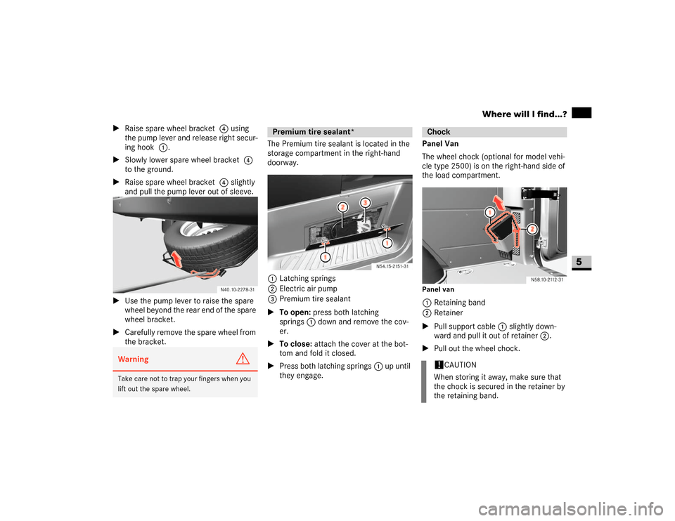
the bracket.The Premium tire sealant is located in the
storage compartment in the right-hand
doorway.
1Latching springs
2Electric air pump
3Premium tire sealant
\1To open: press both latching
springs1 down and remove the cov-
er.
\1To close: attach the cover at the bot-
tom and fold it closed.
\1Press both latching springs1 up until
they engage.Panel Van
The wheel chock (optional for model vehi-
cle type 2500) is on the right-hand side of
the load compartment.
Panel van1Retaining band
2Retainer
\1Pull support cable 1 slightly down-
ward and pull it out of retainer 2.
\1Pull out the wheel chock.
Warning
G
Take care not to trap your fingers when you
lift out the spare wheel.
Premium tire sealant*
Chock!
CAUTION
When storing it away, make sure that
the chock is secured in the retainer by
the retaining band.
Page 305 of 393
304 Practical hintsWhere will I find...?
5
Chassis
The wheel chock is on the left-hand side
behind the rear axle.
Example illustration of chassis
\1Pull the retainer springs down and re-
move the chock.If it is no longer possible to close the slid-
ing sunroof, you can close it manually by
operating the drive located behind the trim
at the front of the sliding sunroof.
1Trim
2Cover cap
\1Remove cover cap2 from trim1.3Opening
4Emergency operation key
\1Take emergency operation key 4 from
the vehicle document wallet in the
glove box.
\1Insert emergency operation key 4 into
opening3 of the drive.
\1Open or close the sliding sunroof by
turning it in the appropriate direction.
\1Pull out emergency operation key 4
and place it in the vehicle document
wallet.
\1Clip cover cap2 back on.
!
CAUTION
When storing it away, make sure that
the chock is secured in the retainer by
the retainer springs.
Sliding sunroof*
N77.20-2041-31
N77.20-2040-31
Page 311 of 393
310 Practical hintsChanging bulbs
5
Changing the rear bulbs
(van / crewbus)
\1Switch off the lighting.
Rear lamp units
1Securing screws
\1Undo screws1 and remove the rear
lamp unit in the direction of the arrow.
\1Remove the connector.2Retaining lugs
3Brake lamp
4Side marker, Standing lamp (Canada
only), tail lamp
5Reverse lamp
6Turn signal lamp
7Rear foglamp (driver’s side)
\1Release retaining lugs2 and remove
the bulb holder from the rear lamp unit.
\1Press down on the bulb, turn it counter-
clockwise and remove it from the
holder.\1Press the new bulb into the bulb holder
and screw it in clockwise.
\1Plug the connectors into the bulb
holder.
\1Fit the rear lamp unit.
To do this, clip the bulb holder into the
three holes provided on the side and
tighten screws1.
Changing the rear bulbs (chassis)
Example illustration of chassis1Securing screws
2Lens
3Perimeter lamp, side marker
4Turn signal lamp
5Brake lamp
Page 312 of 393
311 Practical hints
Changing bulbs
5
6Tail lamp
7Rear foglamp (driver’s side)
8License plate lamp
9Reverse lamp
\1Switch off the lighting.
\1Undo screws1 and remove lens 2.
\1Press the bulb into the bulb holder and
screw it out in a counterclockwise di-
rection.
\1Press the new bulb into the bulb holder
and screw it in clockwise.
\1Replace lens2 and retighten
screws1.\1Switch off the lighting.
Identification lamps W 5 W (cab chas-
sis only)
\1Switch off the lighting.
\1Undo screws 1 and remove lamp hou-
sing.\1Turn the bulb holder 2and remove it
together with the bulb.
\1Pull the bulb out of the bulb holder 2.
\1Press the new bulb into the bulb holder
2.
\1Screw the bulb holder 2 containing
the bulb into the lamp housing.
\1Carefully reattach the lamp housing
and retighten screws 1.
Changing additional bulbs
1Securing screws
2Bulb holder
Page 313 of 393

312 Practical hintsChanging bulbs
5
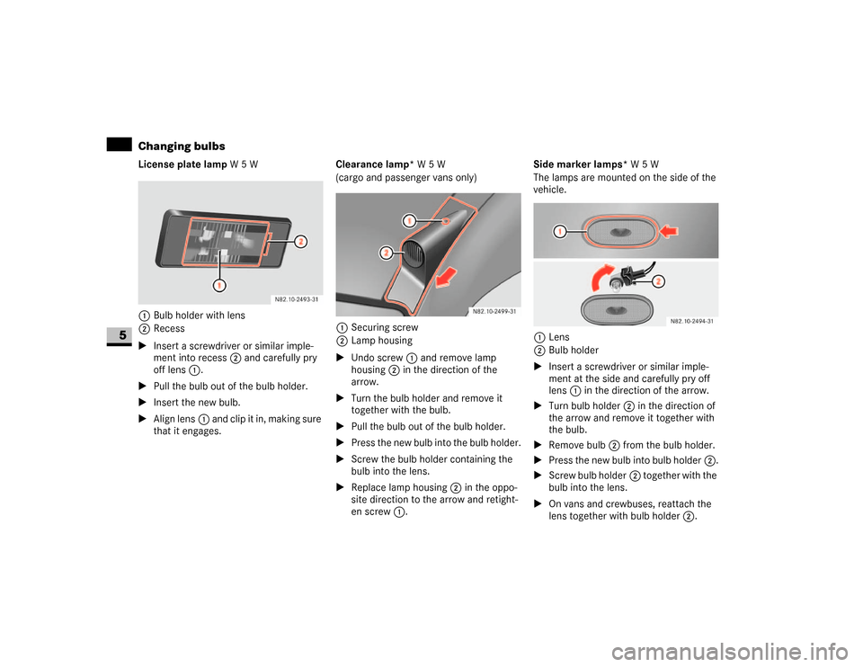
License plate lamp W5W
1Bulb holder with lens
2Recess
\1Insert a screwdriver or similar imple-
ment into recess2 and carefully pry
off lens1.
\1Pull the bulb out of the bulb holder.
\1Insert the new bulb.
\1Align lens1 and clip it in, making sure
that it engages.Clearance lamp* W5W
(cargo and passenger vans only)
1Securing screw
2Lamp housing
\1Undo screw1 and remove lamp
housing2 in the direction of the
arrow.
\1Turn the bulb holder and remove it
together with the bulb.
\1Pull the bulb out of the bulb holder.
\1Press the new bulb into the bulb holder.
\1Screw the bulb holder containing the
bulb into the lens.
\1Replace lamp housing2 in the oppo-
site direction to the arrow and retight-
en screw1.Side marker lamps* W5W
The lamps are mounted on the side of the
vehicle.
1Lens
2Bulb holder
\1Insert a screwdriver or similar imple-
ment at the side and carefully pry off
lens1 in the direction of the arrow.
\1Turn bulb holder2 in the direction of
the arrow and remove it together with
the bulb.
\1Remove bulb2 from the bulb holder.
\1Press the new bulb into bulb holder2.
\1Screw bulb holder2 together with the
bulb into the lens.
\1On vans and crewbuses, reattach the
lens together with bulb holder2.