2007 DODGE SPRINTER weight
[x] Cancel search: weightPage 179 of 393

178 OperationDriving tips
4
Attaching a trailer
Please observe the maximum permitted
trailer dimensions (width and length).
Most states and all Canadian provinces re-
quire safety chains between your tow vehi-
cle and the trailer. The chains should be
crisscrossed under the trailer tongue. They
must be attached to the hitch receiver, and
not to the vehicle’s bumper or axle. Be sure
to leave enough slack in the chains to per-
mit turning corners.Towing a trailer
There are many different laws, including
speed limit restrictions, having to do with
trailer towing. Make sure that your vehicle-
trailer combination will be legal, not only
for where you reside, but also for where
you will be driving. A good source for this
information can be the police or local au-
thorities.
Before you start driving with the trailer,
check the trailer hitch, break-away switch,
safety chains, electrical connections, light-
ing and tires. Also adjust the mirrors to
permit an unobstructed view beyond the
rear of the trailer.
If the trailer has electric brakes, start your
vehicle and trailer moving slowly, and then
apply only the trailer brake controller by
hand to be sure that the brakes are work-
ing properly.
When towing a trailer, check occasionally
to be sure that the load is secure, and that
lighting and trailer brakes (if so equipped)
are functioning properly.
iMost states and all Canadian provinces
require a separate brake system at var-
ious trailer weights.
Warning
G
Do not connect a trailer brake system (if
trailer is so equipped) directly to the vehi-
cle’s hydraulic brake system as your vehicle
is equipped with antilock brakes. If you do,
neither the vehicle’s brakes nor the trailer’s
brakes will function properly. This could
cause an accident resulting in property dam-
age, injury or death to you or others.
The provided vehicle electrical wiring har-
ness for trailer towing has a brake signal
wire for hook-up to a brake controller.
Most states and all Canadian provinces re-
quire a break-away switch on trailers with a
separate brake system. The switch activates
the trailer brakes in the possible event that
the trailer might separate from the tow vehi-
cle.
You should consider using a trailer sway
control system. For further information, see
your authorized Sprinter Dealer.
Page 206 of 393

205 Operation
Tires and wheels
4
The following labels on the vehicle show
how much weight it may properly carry.
\4Only vehicles with a gross weight ca-
pacity less than 10,000 lbs (4500 kg)
The tire and loading information plac-
ard can be found on the driver’s door B-
pillar. This placard tells you important
information about the number of peo-
ple that can be in the vehicle and the
total weight that can be carried in the
vehicle.
It also contains information on the
proper size and recommended tire in-
flation pressures for the original equip-
ment tires on your vehicle.
\4The certification label can be found be-
low the driver’s seat on an outward fac-
ing position of the mounting pillar
(\2page 373). This label tells you about
the gross weight capacity of your vehi-
cle, called the Gross Vehicle Weight
Rating (GVWR). The GVWR includes the
weight of the vehicle, all occupants,
fuel and cargo. The certification label also tells you about the front and rear
axle weight capacity, called the Gross
Axle Weight Rating (GAWR). The GAWR
is the total allowable weight that can be
carried by a single axle (front or rear).
Never exceed the GVWR or GAWR for
either the front axle or rear axle.
1Tire and loading information placard on
driver’s door B-pillar
The information below explains how to
work with the information contained on the
placard with regards to loading your vehi-
cle.Tire and loading informationLoading the vehicle
Warning
G
Do not overload the tires by exceeding the
specified load limit as indicated on the tire
and loading information placard on the driv-
er’s door B-pillar or on the certification label
below the driver’s seat on the mounting pil-
lar. Overloading the tires can overheat them,
possibly causing a blowout. Overloading the
tires can also result in handling or steering
problems, or brake failure.
Overloading of tires is dangerous. Overload-
ing can cause tire failure, affect vehicle han-
dling, and increase the stopping distance.
Use tires of the recommended load capacity
for the vehicle. Never overload them.
The vehicle maximum load on the tire must
not exceed the load carrying capacity of the
tire on your vehicle. You will not exceed the
tire’s load carrying capacity if you adhere to
the loading conditions, tire size and cold tire
inflation pressures specified on the tire and
loading information placard, tire pressure la-
bel and this section.
Page 207 of 393

206 OperationTires and wheels
4
Placard
For vehicles with a gross weight capacity
less than 10,000 lbs (4500 kg) only.
The tire and loading information placard is
located on the driver’s door B-pillar.Tire and loading information placard1Seating capacity
2Load limit informationSeating capacity
The seating capacity1 gives you impor-
tant information on the number of occu-
pants that can be in the vehicle. Observe
front and rear seating capacity.
Never let more people ride in the vehicle
than there are designated seating posi-
tions and seat belts available. Make sure
that everyone riding in the vehicle is cor-
rectly restrained with a separate seat belt.Load limit information
Locate the statement “The combined
weight of occupants and cargo should nev-
er exceed XXX kilograms or XXX lbs.” 2
on the tire and loading information plac-
ard. The combined weight of all occupants,
cargo/luggage and trailer tongue load (if
applicable) should never exceed the
weight referenced in that statement.
Steps for determining correct load limit
For vehicles with a gross weight capacity
less than 10,000 lbs (4500 kg) only.
The following steps have been developed
as required of all manufacturers under Title
49, Code of U.S. Federal Regulations, Part
575 pursuant to the “National Traffic and
Motor Vehicle Safety Act of 1966”.
iThe data shown on this placard is for il-
lustrative purposes only. The load limit
data and seating data are specific to
each vehicle and may vary from the
data shown in the illustration below.
Refer to the placard on your vehicle for
actual data specific to your vehicle.
Page 208 of 393

207 Operation
Tires and wheels
4
Step 1
\1Locate the statement “The combined
weight of occupants and cargo should
never exceed XXX kg or XXX lbs.” on
your vehicle’s placard.
Step 2
\1Determine the combined weight of the
driver and passengers that will be
riding in your vehicle.
Step 3
\1Subtract the combined weight of the
driver and passengers from
XXX kilograms or XXX lbs.Step 4
\1The resulting figure equals the avail-
able amount of cargo and luggage load
capacity. For example, if the “XXX”
amount equals 1400 lbs and there will
be five 150 lbs passengers in your vehi-
cle, the amount of available cargo and
luggage load capacity is 650 lbs (1400-
750 (5 x150) = 650 lbs).
Step 5
\1Determine the combined weight of lug-
gage and cargo being loaded on the ve-
hicle. That weight may not safely
exceed the available cargo and luggage
load capacity calculated in step 4.Step 6 (if applicable)
\1If your vehicle will be towing a trailer,
load from your trailer will be trans-
ferred to your vehicle. Consult this
manual to determine how this reduces
the available cargo and luggage load
capacity of your vehicle.
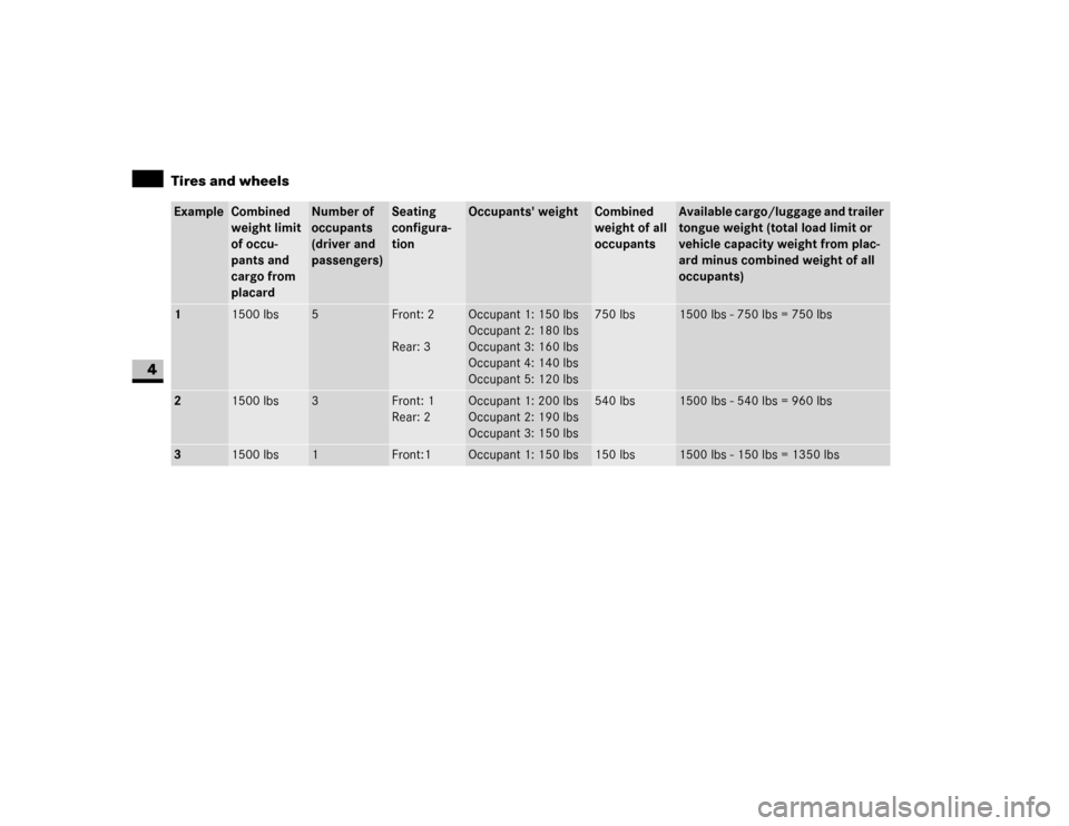
The following table shows examples on
how to calculate total load, cargo load and
towing capacities with varying seating con-
figurations and number and size of occu-
pants. The following examples use a load
limit of 1500 lbs. This is for illustrative
purposes only. Make sure you are using
the actual load limit for your vehicle stated
on the vehicle’s tire and loading informa-
tion placard (\2page 206).
The higher the weight of all occupants, the
less cargo and luggage load capacity is
available.
Page 209 of 393

208 OperationTires and wheels
4
Example
Combined
weight limit
of occu-
pants and
cargo from
placard
Number of
occupants
(driver and
passengers)
Seating
configura-
tion
Occupants' weight
Combined
weight of all
occupants
Available cargo/luggage and trailer
tongue weight (total load limit or
vehicle capacity weight from plac-
ard minus combined weight of all
occupants)
1
1500 lbs
5
Front: 2
Rear: 3
Occupant 1: 150 lbs
Occupant 2: 180 lbs
Occupant 3: 160 lbs
Occupant 4: 140 lbs
Occupant 5: 120 lbs
750 lbs
1500 lbs - 750 lbs = 750 lbs
2
1500 lbs
3
Front: 1
Rear: 2
Occupant 1: 200 lbs
Occupant 2: 190 lbs
Occupant 3: 150 lbs
540 lbs
1500 lbs - 540 lbs = 960 lbs
3
1500 lbs
1
Front:1
Occupant 1: 150 lbs
150 lbs
1500 lbs - 150 lbs = 1350 lbs
Page 210 of 393

209 Operation
Tires and wheels
4
Certification label
Even after careful determination of the
combined weight of all occupants, cargo
and the trailer tongue load (if applicable)
as to not exceed the permissible load limit,
you must make sure that your vehicle nev-
er exceeds the Gross Vehicle Weight Rat-
ing (GVWR) and the Gross Axle Weight
Rating (GAWR) for either the front or rear
axle and the Gross Combination Weights
Rating (GCWR) (if applicable).
Under a maximum loaded vehicle condi-
tion, gross axle weight ratings (GAWR’s) for
the front and rear axles must not be ex-
ceeded. USA only - for vehicles with a gross weight
capacity less than 10,000 lbs (4500 kg)
only:
To determine the maximum loading condi-
tions of your vehicle, locate the statement
"The combined weight of occupants and
cargo should never exceed XXX kg or
XXX lbs." on the tire and loading informa-
tion placard. The combined weight of occu-
pants, cargo/luggage and trailer tongue
weight (if applicable) should never exceed
the weight referenced here.
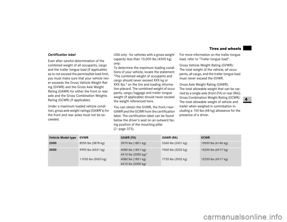
You can obtain the GVWR, the front/rear-
GAWR and the GCWR from the certification
label. The certification label can be found
below the driver’s seat on an outward fac-
ing position of the mounting pillar
(\2page 373).For more information on the trailer tongue
load, refer to "Trailer tongue load".
Gross Vehicle Weight Rating (GVWR):
The total weight of the vehicle, all occu-
pants, all cargo, and the trailer tongue load
must never exceed the GVWR.
Gross Axle Weight Rating (GAWR):
The total allowable weight that can be car-
ried by a single axle (front (FA) or rear (RA)).
Gross Combination Weight Rating (GCWR):
The total allowable weight of vehicle and
trailer when weighed in cominbation in-
cluding a 150 lbs (68 kg) allowance for the
presence of a driver.
Vehicle Model type
GVWR
GAWR (FA)
GAWR (RA)
GCWR
2500
8550 lbs (3878 kg)
3970 lbs (1801 kg)
5360 lbs (2431 kg)
13550 lbs (6146 kg)
3500
9990 lbs (4531 kg)
11030 lbs (5003 kg)
4080 lbs (1851 kg)
4410 lbs (2000 kg)*
4080 lbs (1851 kg)
4410 lbs (2000 kg)
7060 lbs (3202 kg)
7720 lbs (3502 kg)
15250 lbs (6917 kg)
15250 lbs (6917 kg)
Page 211 of 393

210 OperationTires and wheels
4
To assure that your vehicle does not ex-
ceed the maximum permissible weight lim-
its (GVWR and GAWR for front and rear
axle), have the loaded vehicle (including
driver, passengers and all cargo and, if ap-
plicable, trailer fully loaded) weighed on a
suitable commercial scale.
Trailer tongue load
The tongue load (tongue weight at the
hitch ball) of any trailer is an important
weight to measure because it affects the
load you can carry in your vehicle. If a trail-
er is towed, the tongue load must be added
to the weight of all occupants riding and
any cargo you are carrying in the vehicle to
prevent exceeding your Sprinter tow vehi-
cle’s rear GAWR. The tongue load typically
is between 10% and 15% of the trailer
weight and everything loaded in it.
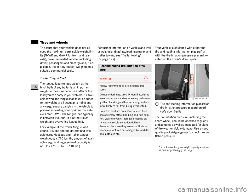
For example, if the trailer tongue load
equals 1 40 lbs and the determined avail-
able cargo/luggage and trailer tongue
weight equals 750 lbs, the amount of avail-
able cargo and luggage load capacity is
610 lbs. (750 – 140 = 610 lbs.)For further information on vehicle and trail-
er weights and ratings, loading a trailer and
trailer towing, see “Trailer towing”
(\2page 175).Your vehicle is equipped with either the
tire and loading information placard
1 or
with the tire inflation pressure placard lo-
cated on the driver’s door B-pillar.
The tire inflation pressure (including the
spare wheel) should be checked regularly
and adjusted as well as inspected for signs
of tire wear or visible damage. Use a good
quality pocket-type gauge to check tire in-
flation pressure.
Recommended tire inflation pres-
sureWarning
G
Follow recommended tire inflation pres-
sures.
Do not underinflate tires. Underinflated tires
wear excessively and/or unevenly, adverse-
ly affect handling and fuel economy, and are
more likely to fail from being overheated.
Do not overinflate tires. Overinflated tires
can adversely affect handling and ride com-
fort, wear unevenly, increase stopping dis-
tance, and result in sudden deflation
(blowout) because they are more likely to
become punctured or damaged by road de-
bris, potholes etc.
1. For vehicles with a gross weight capacity less than
10 000 lbs (4 536 kg) (USA only).1Tire and loading information placard or
tire inflation pressure placard on dri-
ver’s door B-pillar
Page 212 of 393

211 Operation
Tires and wheels
4
Do not make a visual judgment when de-
termining proper inflation. Radial tires may
look properly inflated even when they are
underinflated.
The tire inflation pressure should be
checked regularly, i.e. at least each time
you refuel the vehicle, and should only be
adjusted on cold tires. The preferred inter-
val for checking the tire inflation pressure,
however, is before each trip.
The tires can be considered cold if the ve-
hicle has been parked for at least 3 hours
or driven less than 1 mile (1.6 km) at an
ambient temperature of approximately
68 °F (20 °C).
Follow recommended cold tire inflation
pressures listed on vehicle placard.
Keeping the tires properly inflated provi-
des the best handling, tread life and riding
comfort.
The pressure difference between the tires
on a single axle should not exceed 1.5 psi
(10 kPa).
In addition to the placard, also consult the
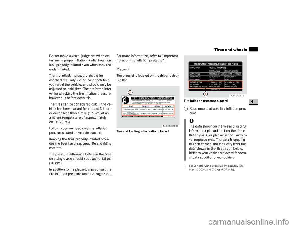
tire inflation pressure table (\2page 370).For more information, refer to “Important
notes on tire inflation pressure”.
Placard
The placard is located on the driver’s door
B-pillar.
Tire and loading information placardTire inflation pressure placard
1Recommended cold tire inflation pres-
sure
iThe data shown on the tire and loading
information placard
1and on the tire in-
flation pressure placard is for illustrati-
ve purposes only. Tire data is specific
to each vehicle and may vary from the
data shown in the illustration below.
Refer to your vehicle’s placard for actu-
al data specific to your vehicle.
1 For vehicles with a gross weight capacity less
than 10 000 lbs (4 536 kg) (USA only).