Page 107 of 384

To Resume Speed:
If you deactivated the speed control without erasing the
set speed from memory and your vehicle speed is above
20 mph (32 km/h) you can resume the previous set
speed. To do so, push the lever up and release (RES/
ACCEL), and then remove your foot from the accelerator
pedal.
To Vary the Speed Setting:
When the speed control is set, you can increase speed by
pushing the lever up and holding (“RES/ACCEL”).
When the lever is released, a new set speed will be
established.
Pushing the lever up and releasing (“RES/ACCEL”) once
will result in a 1 mph (1.6 km/h) speed increase. Each
time the lever is pushed up and released, speed increases
so that pushing the lever up and releasing three times
will increase speed by 3 mph (4.8 km/h), etc.
To decrease speed while speed control is set, push the
lever down and hold (“SET/DECEL”). Release the lever
when the desired speed is reached, and a new set speed
will be established.Pushing down and releasing the lever (“SET/DECEL”)
once will result in a 1 mph (1.6 km/h) speed decrease.
Each time the lever is pushed down and released, speed
decreases.
To Accelerate For Passing:
Depress the accelerator as you would normally. When the
pedal is released, the vehicle will return to the set speed.
NOTE:The speed control system maintains speed up
and down hills. A slight speed change on moderate hills
is normal.
Four speed automatic transmissions will experience a
downshift to 3rd gear while climbing uphill or descend-
ing downhill. This downshift to 3rd gear is necessary to
maintain vehicle set speed.
On steep hills, a greater speed loss or gain may occur so
it may be preferable to drive without speed control.
UNDERSTANDING THE FEATURES OF YOUR VEHICLE 107
3
Page 108 of 384
WARNING!
Speed Control can be dangerous where the system
can’t maintain a constant speed. Your vehicle could
go too fast for the conditions, and you could lose
control. An accident could be the result. Don’t use
Speed Control in heavy traffic or on roads that are
winding, icy, snow-covered, or slippery.
OVERHEAD CONSOLE
The overhead console contains courtesy/reading lights,
an optional universal garage door opener (HomeLink�),
storage for sunglasses, and an optional power sunroof
switch.
Courtesy/Reading Lights
At the forward end of the console are two courtesy/
reading lights.
Press the lens to turn on the light. Press it a second time
to turn off the light.
These lights also turn on when a door is opened, or when
the unlock button on the remote keyless entry transmitter
is pressed, or when the dimmer control is turned fully
upward, past the second detent.
Overhead Console
108 UNDERSTANDING THE FEATURES OF YOUR VEHICLE
Page 109 of 384

Sunglasses Storage
At the rear of the console, a compartment is provided for
the storage of a pair of sunglasses.
The storage compartment access is a�push/push�design.
Push the finger depression on the overhead console to
open. Push the finger depression to close.
GARAGE DOOR OPENER (HomeLink�)—IF
EQUIPPED
The HomeLink�Universal Transceiver replaces up to
three remote controls (hand held transmitters) that oper-
ate devices such as garage door openers, motorized
gates, or home lighting. It triggers these devices at the
push of a button. The Universal Transceiver operates off
your vehicle’s battery and charging system; no batteries
are needed.
NOTE:The HomeLink�Universal Transceiver is dis-
abled when the Vehicle Security Alarm is active.
For additional information on HomeLink�, call 1–800–
355–3515, or on the internet at www.homelink.com.
WARNING!
•A moving garage door can cause injury to people
and pets in the path of the door. People or pets
could be seriously or fatally injured. Only use this
transceiver with a garage door opener that has a
“stop and reverse” feature as required by federal
safety standards. This includes most garage door
opener models manufactured after 1982. Do not
use a garage door opener without these safety
features it could cause injury or death. Call toll-
free 1–800–355–3515 or, on the Internet at
www.homelink.com for safety information or as-
sistance.
•Vehicle exhaust contains carbon monoxide, a dan-
gerous gas. Do not run the vehicle’s exhaust while
training the transceiver. Exhaust gas can cause
serious injury or death.
•Your motorized door or gate will open and close
while you are training the Universal Transceiver.
Do not train the transceiver if people or pets are in
the path of the door or gate. A moving door or gate
can cause serious injury or death to people and
pets or damage to objects.
UNDERSTANDING THE FEATURES OF YOUR VEHICLE 109
3
Page 113 of 384

NOTE:If programming a garage door opener or gate
operator, it is advised to unplug the device during the
�cycling�process to prevent possible overheating.
3. Continue to press and hold the HomeLink button
while youpress and releaseyour hand-held transmitter
every two secondsuntil the frequency signal is accepted
successfully by HomeLink. The EVIC will display “Chan-
nel X Trained” (where X is Channel 1, 2, or 3). Proceed
with�Programming�Step 4 to complete the procedure.
Using HomeLink
To operate, simply press and release the programmed
HomeLink button. Activation will now occur for the
trained device (i.e. garage door opener, gate operator,
security system, entry door lock, home/office lighting,
etc.). For convenience, the hand-held transmitter of the
device may also be used at any time. In the event that
there are still programming difficulties or questions,
contact HomeLink atwww.homelink.com or 1-800-355-
3515.
Erasing HomeLink Buttons
To erase programming from the three buttons (individual
buttons cannot be erased but can be�reprogrammed�-
note below), follow the step noted:
•Press and hold the two outer HomeLink buttons.
Release the buttons only when the EVIC displays
“Channels Cleared” (after 20 seconds); however,do
nothold the buttons for longer than 30 seconds.
HomeLink is now in the train (or learning) mode and
can be programmed at any time beginning with�Pro-
gramming�Step 2.
Reprogramming a Single HomeLink Button
To program a device a previously trained HomeLink
button, follow these steps:
1. Press and hold the desired HomeLink button.Do
NOTrelease the button.
2. The EVIC will display “Channel X Transmit” (where X
is Channel 1, 2, or 3) for 20 seconds and then change to
“Channel X Training.” Without releasing the HomeLink
button, proceed with�Programming�Step 2.
UNDERSTANDING THE FEATURES OF YOUR VEHICLE 113
3
Page 117 of 384

For vehicles equipped with the EVIC, the power sunroof
switch will remain active for up to 60 minutes after the
ignition switch is turned off. Opening either front door
will cancel this feature. The time is programmable. For
details, refer to “Delay Power Off to Accessories Until
Exit,” under “Personal Settings (Customer Program-
mable Features),” under “Electronic Vehicle Information
Center (EVIC)” in Section 4 of this manual.
Sunroof Fully Closed
Press the switch forward and release to ensure that the
sunroof is fully closed.
ELECTRICAL POWER OUTLETS
There are two 12-volt electrical outlets on this vehicle.
Both of the outlets are protected by a fuse.
The 12-volt power outlet next to the ash receiver tray (if
equipped with an optional Smoker’s Package) has power
available only when the ignition is on. This outlet will
also operate a conventional cigar lighter unit.
WARNING!
Do not place ashes inside the cubby bin located on
the center console on vehicles not equipped with the
ash receiver tray. A fire leading to bodily injury
could result.
NOTE:If desired, the power outlet next to the ash
receiver tray (if equipped) can be converted by your
authorized dealer to provide power with the ignition
switch in the LOCK position.
Front Power Outlet
UNDERSTANDING THE FEATURES OF YOUR VEHICLE 117
3
Page 118 of 384

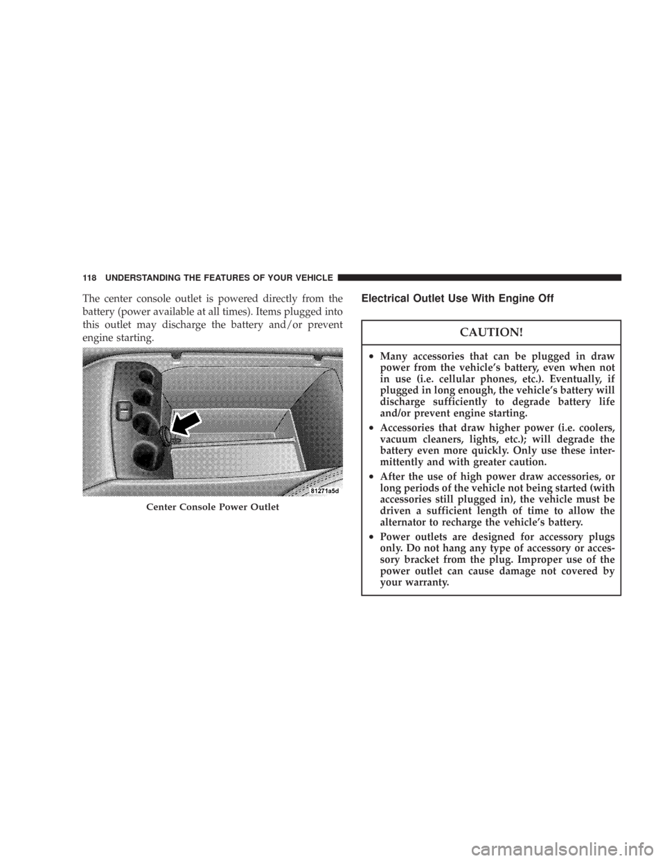
The center console outlet is powered directly from the
battery (power available at all times). Items plugged into
this outlet may discharge the battery and/or prevent
engine starting.Electrical Outlet Use With Engine Off
CAUTION!
•Many accessories that can be plugged in draw
power from the vehicle’s battery, even when not
in use (i.e. cellular phones, etc.). Eventually, if
plugged in long enough, the vehicle’s battery will
discharge sufficiently to degrade battery life
and/or prevent engine starting.
•Accessories that draw higher power (i.e. coolers,
vacuum cleaners, lights, etc.); will degrade the
battery even more quickly. Only use these inter-
mittently and with greater caution.
•After the use of high power draw accessories, or
long periods of the vehicle not being started (with
accessories still plugged in), the vehicle must be
driven a sufficient length of time to allow the
alternator to recharge the vehicle’s battery.
•Power outlets are designed for accessory plugs
only. Do not hang any type of accessory or acces-
sory bracket from the plug. Improper use of the
power outlet can cause damage not covered by
your warranty.
Center Console Power Outlet
118 UNDERSTANDING THE FEATURES OF YOUR VEHICLE
Page 126 of 384
INSTRUMENT PANEL AND CONTROLS
1 — Air Outlet 6 — Radio 11 — Ignition Switch
2 — Instrument Cluster 7 — Climate Control 12 — Hood Release
3 — Hazard Switch 8 — Heated Seat Switch* 13 — Trunk Release Switch
4 — Electronic Stability Program Off Button* /
Traction Control System Off Button*9 — Power Outlet 14 — Headlight Switch
5 — Glove Box 10 — Ash Tray* * If Equipped 126 UNDERSTANDING YOUR INSTRUMENT PANEL
Page 129 of 384

INSTRUMENT CLUSTER DESCRIPTIONS
1. Fuel Gauge
The pointer shows the level of fuel in the fuel tank when
the ignition switch is in the ON position.
2. Trip Odometer Button
Base Cluster
The word�TRIP�will appear when this button is pressed.
Push in and hold the button for two seconds when the
trip odometer displays to reset it to 0 miles (kilometers).
A second press of the button will display the outside
temperature in the odometer.
Premium Cluster
Press this button to change the display from odometer to
either of two trip odometer settings. The letter “A” or “B”
will appear when in the trip odometer mode. Push in and
hold the button for two seconds to reset the trip odometer
to 0 miles (kilometers). The odometer must be in trip
mode to reset it.
3. Speedometer
Indicates vehicle speed.
4. Electronic Speed Control Indicator Light — If
Equipped
This light will turn on when the electronic
speed control is ON. (See page 105 for more
information.)
5. Tachometer
The red segments indicate the maximum permissible
engine revolutions-per-minute (r.p.m. x 1000) for each
gear range. Ease up on the accelerator before reaching the
red area.
6. Voltage Light
This light monitors the electrical system volt-
age. The light should turn on momentarily as
the engine is started. If the light stays on or turns on
while driving, it indicates a problem with the charging
system. Immediate service should be obtained.
UNDERSTANDING YOUR INSTRUMENT PANEL 129
4