Page 149 of 520

WARNING!
•Not all head restraints in this vehicle are the
same. Head restraints from one seating position
should not be removed and installed in any other
seating position. In a collision, serious injury or
death may result if the proper head restraint is
not installed on each seat.
•The cargo area in the rear of the vehicle should
not be used as a play area by children. They could
be seriously injured in a collision. Children
should be seated and using the proper restraint
system.
•It is extremely dangerous to ride in a cargo area,
inside or outside of a vehicle. In a collision,
people riding in these areas are more likely to be
seriously injured or killed.
•Do not allow people to ride in any area of your
vehicle that is not equipped with seats and seat belts.
•Be sure everyone in your vehicle is in a seat and
using a seat belt properly.
TO OPEN AND CLOSE THE HOOD
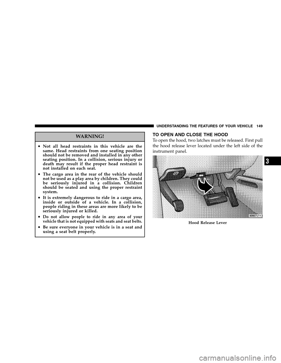
To open the hood, two latches must be released. First pull
the hood release lever located under the left side of the
instrument panel.
Hood Release Lever
UNDERSTANDING THE FEATURES OF YOUR VEHICLE 149
3
Page 150 of 520
Next, push to the left the safety catch located under the
front edge of the hood, near the center.
Use the hood prop rod to secure the hood in the open
position.
To prevent possible damage, do not slam the hood to
close it. Lower the hood until it is open approximately 30 cm (12 inches) and then drop it. This should secure both
latches. Never drive your vehicle unless the hood is fully
closed, with both latches engaged.
WARNING!
If the hood is not fully latched, it could fly up when
the vehicle is moving and block your forward vision.
You could have a collision. Be sure all hood latches
are fully latched before driving.
LIGHTS
All of the lights, except the hazard warning lights, are
controlled by switches to the left of the steering column
on the instrument panel.
Hood Safety Catch
150 UNDERSTANDING THE FEATURES OF YOUR VEHICLE
Page 155 of 520
MULTIFUNCTION LEVER
Turn Signals
Move the Multifunction Lever up or down and the
arrows on each side of the base instrument cluster or
Information Center flash to indicate proper operation of
the front and rear turn signal lights. You can signal a lane
change by moving the lever partially up or down.
If either indicator flashes at a rapid rate, check for a
defective outside turn signal light bulb. If one of the
indicators fails to light when the lever is moved, it would
suggest that the indicator light is defective.
Turn Signal Warning
If the vehicle electronics sense that the vehicle has
traveled at over 18 mph (29 km/h) for about one mile
with the turn signals on, a chime will sound to alert the
driver.
Turn Signal Switch
UNDERSTANDING THE FEATURES OF YOUR VEHICLE 155
3
Page 157 of 520

wipers will operate for several seconds after the lever is
released, and then resume the intermittent interval pre-
viously selected.
If the end of the lever is depressed while in the OFF
position, the wipers will operate for approximately two
wipe cycles, then turn OFF.
WARNING!
Sudden loss of visibility through the windshield
could lead to an accident. You might not see other
vehicles or other obstacles. To avoid sudden icing of
the windshield during freezing weather, warm the
windshield with defroster before and during wind-
shield washer use.
Intermittent Wiper System
Use the intermittent wipers when weather conditions
make a single wiping cycle, with a variable pause be-
tween cycles, desirable.
Rotate the end of the lever to the first detent position,
then turn the end of the lever to select the desired delay
interval. The delay can be regulated from a maximum of
about 20 seconds between cycles, to a cycle every 2
seconds. The time delay will be doubled if the vehicle
speed is less than 10 mph (16 km/h).
UNDERSTANDING THE FEATURES OF YOUR VEHICLE 157
3
Page 158 of 520
TILT STEERING COLUMN — IF EQUIPPED
To tilt the column, pull the small lever, located behind the
turn signal control, toward you and move the wheel up
or down, as desired. Release the lever to lock the wheel
firmly in place.WARNING!
Tilting the steering column while the vehicle is
moving is dangerous. Without a stable steering col-
umn, you could lose control of the vehicle and have
an accident. Adjust the column only while the ve-
hicle is stopped. Be sure it is locked before driving.
TRACTION CONTROL SWITCH — IF EQUIPPED
The TRAC indicator, located below the instrument clus-
ter odometer, will light up when the Traction Control is in
use.
To turn the system OFF, press the TRAC OFF switch
located on the steering column, until the TRAC OFF
indicator below the instrument cluster odometer lights
up.
Tilt Steering Column Control
158 UNDERSTANDING THE FEATURES OF YOUR VEHICLE
Page 160 of 520
When the driver selects Reverse the system scans for
objects behind the vehicle using four sensors located in
the rear bumper. Objects can be detected from up to 59
inches (150 cm). A warning display above the rear
window provides both visible and audible warnings
indicating the distance of the object. The warning display contains two sets of yellow and red
LEDs, one set to warn of obstacles behind the left rear of
the vehicle and the other set to warn of obstacles behind
the right rear of the vehicle. The driver can view the LEDs
either through the rear view mirror or by looking at the
display above the rear window.
The system dimly illuminates the two outer most yellow
LEDs when it is ON and detecting no obstacles. The
following chart shows the warning display operation
when the system is detecting an obstacle:
Rear Park Sense Indicator
160 UNDERSTANDING THE FEATURES OF YOUR VEHICLE
Page 161 of 520
WARNING DISPLAY DISTANCES
DISPLAY LED OBSTACLE DISTANCE FROM: LED COLOR AUDIBLE SIGNAL REAR CORNERS REAR CENTER
1st LED 59 in. (150 cm) Yellow None
2nd LED 47 in. (120 cm) Yellow None 3rd LED 39 in. (100 cm) Yellow None4th LED 31.5 in. (80 cm) 31.5 in. (80 cm) Yellow None
5th LED 25.5 in. (65 cm) 25.5 in. (65 cm) Yellow None
6th LED 20 in. (50 cm) 20 in. (50 cm) Yellow None
7th LED 16 in. (40 cm) 16 in. (40 cm) Red at 12 in. (30 cm) In- termittent
8th LED 6 in. (15 cm) 12 in. (30 cm) Red at 8 in. (20 cm) Con- tinuous
NOTE: The Rear Park Sense System will MUTE the
radio, if on, when the audible warning is activated.
UNDERSTANDING THE FEATURES OF YOUR VEHICLE 161
3
Page 162 of 520

WARNING!
•Drivers must be careful when backing up even
when using the Rear Park Sense System. Always
check carefully behind your vehicle, and be sure to
check for pedestrians, animals, other vehicles, ob-
structions, or blind spots before backing up. You are
responsible for the safety of your surroundings and
must continue to pay attention while backing up.
Failure to do so can result in serious injury or death.
•Before using the Rear Park Sense System, it is
strongly recommended that the ball mount and
hitch ball assembly be disconnected from the ve-
hicle when the vehicle is not used for towing.
Failure to do so can result in injury or damage to
vehicles or obstacles because the hitch ball will be
much closer to the obstacle than the rear fascia when
the warning display turns the red LEDs ON. Also,
the sensors could detect the ball mount and hitch
ball assembly, depending on its size and shape,
giving a false indication that an obstacle is behind
the vehicle.
CAUTION!
•To avoid vehicle damage the Rear Park Sense
System should only be used as a parking aid and
is unable to recognize every obstacle, including
small objects. Parking curbs might be temporarily
detected or not detected at all. Obstacles located
above or below the sensors will not be detected
when they are in close proximity to the rear of the
vehicle.
•To avoid vehicle damage the vehicle must be
driven slowly when using the Rear Park Sense
System to be able to stop in time when an obstacle
is detected. It is recommended that the driver look
over his/her shoulder when using the Rear Park
Sense System.
162 UNDERSTANDING THE FEATURES OF YOUR VEHICLE