Page 64 of 464

WARNING!
Deployed airbags, front seat belt buckle pretension-
ers and driver inflatable knee blocker cannot protect
you in another collision. Have the airbags, front seat
belt buckle pretensioners and driver inflatable knee
blocker replaced by an authorized dealer as soon as
possible. Also, have the Occupant Classification
System serviced as well.
Enhanced Accident Response
If the airbags and seat belt pretensioners deploy after an
impact and the electrical system remains functional,
vehicles equipped with power door locks will unlock
automatically. In addition, approximately 10 seconds
after the vehicle has stopped moving, the interior lights
will illuminate until the ignition switch is turned off.
Maintaining Your Airbag System
WARNING!
•Modifications to any part of the airbag system could cause
it to fail when you need it. You could be injured because
the airbags are not there to protect you. Do not modify the
components or wiring, including adding any kind of
badges or stickers to the steering wheel hub trim cover or
the upper right side of the instrument panel. Do not
modify the front bumper, vehicle body structure, or frame.
•Do not attempt to modify any part of your advanced airbag
system. The airbag may inflate accidentally or may not
function properly if modifications are made. Take your
vehicle to an authorized dealer for any advanced airbag
system service. If your seat including your trim cover and
cushion needs to be serviced in any way (including re-
moval or loosening/tightening of seat attachment bolts),
take the vehicle to your authorized dealer. Only manufac-
turer approved seat accessories may be used. If it is
necessary to modify an advanced airbag system for per-
sons with disabilities, contact your authorized dealer.
64 THINGS TO KNOW BEFORE STARTING YOUR VEHICLE
Page 81 of 464
Periodic Safety Checks You Should Make Outside
The Vehicle
Tires
Examine tires for excessive tread wear or uneven wear
patterns. Check for stones, nails, glass, or other objects
lodged in the tread. Inspect tread and sidewall for cuts or
cracks. Check wheel nuts for tightness, and tires (includ-
ing spare) for proper pressure.
Lights
Have someone observe the operation of exterior lights
while you work the controls. Check turn signal and high
beam indicator lights on the instrument panel.
Fluid Leaks
Check area under vehicle after overnight parking for fuel,
engine coolant, oil or other fluid leaks. Also, if gasoline
fumes are detected or fuel, power steering fluid, trans-
mission fluid or brake fluid leaks are suspected, the cause
should be located and corrected immediately.
THINGS TO KNOW BEFORE STARTING YOUR VEHICLE 81
2
Page 141 of 464

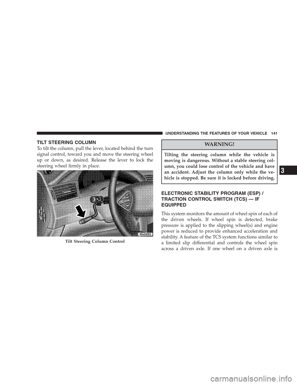
TILT STEERING COLUMN
To tilt the column, pull the lever, located behind the turn
signal control, toward you and move the steering wheel
up or down, as desired. Release the lever to lock the
steering wheel firmly in place.WARNING!
Tilting the steering column while the vehicle is
moving is dangerous. Without a stable steering col-
umn, you could lose control of the vehicle and have
an accident. Adjust the column only while the ve-
hicle is stopped. Be sure it is locked before driving.
ELECTRONIC STABILITY PROGRAM (ESP) /
TRACTION CONTROL SWITCH (TCS) — IF
EQUIPPED
This system monitors the amount of wheel spin of each of
the driven wheels. If wheel spin is detected, brake
pressure is applied to the slipping wheel(s) and engine
power is reduced to provide enhanced acceleration and
stability. A feature of the TCS system functions similar to
a limited slip differential and controls the wheel spin
across a driven axle. If one wheel on a driven axle is
Tilt Steering Column Control
UNDERSTANDING THE FEATURES OF YOUR VEHICLE 141
3
Page 148 of 464
ADJUSTABLE PEDALS — IF EQUIPPED
This feature allows both the brake and accelerator pedals
to move toward or away from the driver to provide
improved position with the steering wheel. The adjust-
able pedal system is designed to allow a greater range of
driver comfort for steering wheel tilt and seat position.
The switch is located on the drivers door trim panel next
to the power seat switches.
Press the switch forward to move the pedals forward
(toward the front of the vehicle).
Adjustable Pedal Switch
148 UNDERSTANDING THE FEATURES OF YOUR VEHICLE
Page 185 of 464

Loose Fuel Filler Cap
If the vehicle diagnostic system determines that the fuel
filler cap is loose, improperly installed, or damaged,
GASCAP will be displayed in the instrument cluster
odometer. Tighten the fuel filler cap properly and press
the odometer reset button to turn the GASCAP message
off. If the problem continues, the message will appear the
next time the vehicle is started. See Section 7 of this
manual for more information.
14. Cruise Indicator
This display indicator shows that the Speed Control
System is ON.
15. Malfunction Indicator Light
This light is part of an onboard diagnostic system
called OBD that monitors engine and automatic
transmission control systems. The light will illu-
minate when the key is in the ON position before enginestart. If the bulb does not come on when turning the key
from OFF to ON, have the condition checked promptly.
Certain conditions such as a loose or missing gas cap,
poor fuel quality, etc. may illuminate the light after
engine start. The vehicle should be serviced if the light
stays on through several of your typical driving cycles. In
most situations the vehicle will drive normally and will
not require towing.
The Malfunction Indicator Light flashes to alert you to
serious conditions that could lead to immediate loss of
power or severe catalytic converter damage. The vehicle
should be serviced as soon as possible if this occurs.
16. High Beam Light
This light shows that the headlights are on high
beam. Pull the Multi-Function lever towards the
steering wheel to switch the headlights from high or low
beam.
UNDERSTANDING YOUR INSTRUMENT PANEL 185
4
Page 201 of 464
Electrical Disturbances
Radio waves may pick up electrical disturbances during
transmission. They mainly affect the wave amplitude,
and thus remain a part of the AM reception. They
interfere very little with the frequency variations that
carry the FM signal.
AM Reception
AM sound is based on wave amplitude, so AM reception
can be disrupted by such things as lightning, power lines
and neon signs.
FM Reception
Because FM transmission is based on frequency varia-
tions, interference that consists of amplitude variations
can be filtered out, leaving the reception relatively clear,
which is the major feature of FM radio.
NOTE:The radio, steering wheel radio controls (if
equipped), and 6 disc CD/DVD changer (if equipped)
will remain active for up to 10 minutes after the ignition
switch has been turned off. Opening a vehicle front door
will cancel this feature.
UNDERSTANDING YOUR INSTRUMENT PANEL 201
4
Page 262 of 464

�Parking Brake.........................276
�Brake System..........................278
▫Anti-Lock Brake System................279
�Electronic Stability Program (ESP)...........281
▫ESP Has The Following Operating Modes....283
▫ESP/BAS Warning Lamp And
ESP/TCS Indicator Light................283
▫Brake Assist System (BAS)...............284
�Traction Control........................285
�Power Steering........................286
�Driving On Slippery Surfaces..............287
▫Acceleration.........................287
▫Traction............................288�Tire Safety Information...................288
▫Tire Markings........................288
▫Tire Identification Number (TIN)..........292
▫Tire Loading And Tire Pressure...........293
�Tires — General Information...............297
▫Tire Pressure.........................297
▫Tire Inflation Pressures.................298
▫Radial-Ply Tires......................300
▫Compact Spare Tire — If Equipped.........301
▫Limited Use Spare — If Equipped.........302
▫Tire Spinning........................302
▫Tread Wear Indicators..................303
▫Life Of Tire.........................304
262 STARTING AND OPERATING
Page 281 of 464

•and a slight drop or fall away of the brake pedal at the
end of the stop.
These are all normal characteristics of ABS.
WARNING!
The Anti-Lock Brake System contains sophisticated
electronic equipment that may be susceptible to
interference caused by improperly installed or high
output radio transmitting equipment. This interfer-
ence can cause possible loss of anti-lock braking
capability. Installation of such equipment should be
performed by qualified professionals.
All vehicle wheels and tires must be the same size and
type and tires must be properly inflated to produce
accurate signals for the computer.
ELECTRONIC STABILITY PROGRAM (ESP)
Your vehicle is equipped with an advanced electronic
brake control system that includes ABS (Anti-Lock Brake
System), TCS (Traction Control System), BAS (Brake
Assist System), ERM (Electronic Roll Mitigation) and ESP
(Electronic Stability Program). All systems work together
to enhance vehicle stability and control in various driving
conditions and are commonly referred to as ESP.
TheESPsystem enhances directional control and stabil-
ity of the vehicle under various driving conditions. ESP
corrects for over/under steering of the vehicle by apply-
ing the brake of the appropriate wheel to assist in
counteracting the over/under steer condition. Engine
power may also be reduced to help the vehicle maintain
the desired path. ESP uses sensors in the vehicle to
determine the vehicle path intended by the driver and
compares it to the actual path of the vehicle. When the
actual path does not match the intended path, ESP
STARTING AND OPERATING 281
5