Page 100 of 360

Interior Lights
The interior lights come on when a door is opened.
To protect the battery, the interior lights will turn off
automatically 10 minutes after the ignition switch is
moved to the LOCK position. This will occur if the
interior lights were switched on manually or are on
because a door is open. This includes the glove box light,
but not the trunk light. To restore interior light operation,
either turn the ignition switch ON or cycle the light
switch.
Dimmer Control
The dimmer control is part of the
headlight switch, and is located on the
left side of the instrument panel. With
the parking lights or headlights on,
rotating the dimmer control upward
will increase the brightness of the in-
strument panel lights.
Dome Light Position
Rotate the dimmer control completely upward to the
second detent to turn on the interior lights. The interior
lights will remain on when the dimmer control is in this
position.
Interior light Defeat (OFF)
Rotate the dimmer control to the extreme bottom “OFF”
position. The interior lights will remain off when the
doors are open.
Parade Mode (Daytime Brightness Feature)
Rotate the dimmer control upward to the first detent.
This feature brightens all text displays such as the
odometer, Electronic Vehicle Information Center (EVIC),
and radio when the parking lights or headlights are on.
100 UNDERSTANDING THE FEATURES OF YOUR VEHICLE
Page 134 of 360
INSTRUMENT PANEL AND CONTROLS
1 — Air Outlet 7 — Radio 13 — Ignition Switch
2 — Instrument Cluster 8 — Climate Control 14 — Hood Release
3 — Hazard Switch 9 — Heated Seat Switch* 15 — Trunk Release Switch
4 — Analog Clock 10 — Power Outlet 16 — Headlight Switch
5—
Electronic Stability Program Off Button* /
Traction Control System Off Button*11 — Ash Tray* * If Equipped
6 — Glove Box 12 — Storage Compartment* 134 UNDERSTANDING YOUR INSTRUMENT PANEL
Page 146 of 360

•Memory #1/#2 Profile Recall
•Memory System Disabled – Vehicle Not In Park (with
a single chime)
•Memory System Disabled – Seat Belt Buckled (with a
single chime)
•Personal Settings Not Available – Vehicle Not in Park
•Left/Right Front Door Ajar (one or more, with a single
chime if speed is above 1 mph [1.6 km])
•Left/Right Rear Door Ajar (one or more, with a single
chime if speed is above 1 mph [1.6 km])
•Door(s) Ajar (with a single chime if vehicle is in
motion)
•Trunk Ajar (with a single chime)
•Low Washer Fluid (with a single chime)
•Adjustable Pedals Disabled – Cruise Engaged (with a
single chime) — only available on vehicles equipped
with memory seats.
•Adjustable Pedals Disabled – Vehicle In Reverse (with
a single chime) — only available on vehicles equipped
with memory seats.
•Channel 1, 2, OR 3 Transmit
•Channel 1, 2, OR 3 Training
•Channel 1, 2, OR 3 Trained
•Clearing Channels
•Channels Cleared
•Channels Defaulted
•Did Not Train
•Left Front Low Pressure (with a single chime). Refer to
information on “Tire Pressure” and “Tire Pressure
Monitor” in the “Starting And Operating” section of
this manual.
•Left Rear Low Pressure (with a single chime). Refer to
information on “Tire Pressure” and “Tire Pressure
Monitor” in the “Starting And Operating” section of
this manual.
146 UNDERSTANDING YOUR INSTRUMENT PANEL
Page 249 of 360
more than a short period, adjust the ventilation system
to force fresh, outside air into the vehicle.
•Guard against carbon monoxide with proper mainte-
nance. Have the exhaust system inspected every time
the vehicle is raised. Have any abnormal conditions
repaired promptly. Until repaired, drive with all side
windows fully open.
•Keep the trunk closed when driving your vehicle to
prevent carbon monoxide and other poisonous ex-
haust gases from entering the vehicle.
ADDING FUEL
Fuel Filler Cap (Gas Cap)
The gas cap is located behind the fuel filler door on the
left side of the vehicle. Push in on the left side (near the
edge) of the fuel filler door to access the fuel filler cap. If
the gas cap is lost or damaged, be sure the replacement
cap is for use with this vehicle.
Fuel Filler Door
STARTING AND OPERATING 249
5
Page 258 of 360
The TIREFIT system is located under an access panel in
the trunk.
1. Air pump hose
2. Power plug and cable
3. Air pump switch
4. Pressure gauge
5. TIREFIT sealant bottle
6. TIREFIT sealant hose
TIREFIT Location
TIREFIT contents
258 WHAT TO DO IN EMERGENCIES
Page 259 of 360

WARNING!
•Do not attempt to repair a tire on the side of the vehicle
close to traffic. Pull far enough off the road to avoid the
danger of being hit when operating the jack or repairing
a tire.
•Cuts or punctures larger than approximately 0.16 in. (4
mm), tire damage caused by driving with extremely low
tire pressure or on a flat tire, or a damaged wheel can
pose a hazard while driving. TIREFIT should not be
used in such circumstances. Do not drive the vehicle
under such circumstances. Contact your nearest autho-
rized dealer for assistance.
•Take care not to allow the contents of TIREFIT to come
in contact with hair, eyes or clothing. TIREFIT is harm-
ful if inhaled, swallowed, or absorbed through the skin:
It causes skin, eye, and respiratory irritation. Any con-
tact with eyes or skin should be flushed immediately
with plenty of water. If clothing comes in contact with
TIREFIT, change clothing as soon as possible.
•In case of allergic reaction or rash, consult a physician
immediately. Keep TIREFIT out of reach of children. If
swallowed, rinse mouth immediately with plenty of
water and drink plenty of water. Do not induce vomit-
ing! Consult a physician immediately.
•Keep away from open flame or heat source.
Sealing tire with TIREFIT
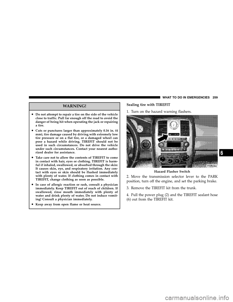
1. Turn on the hazard warning flashers.
2. Move the transmission selector lever to the PARK
position, turn off the engine, and set the parking brake.
3. Remove the TIREFIT kit from the trunk.
4. Pull the power plug (2) and the TIREFIT sealant hose
(6) out from the TIREFIT kit.
Hazard Flasher Switch
WHAT TO DO IN EMERGENCIES 259
6
Page 261 of 360

19. With a tire pressure of no less than 26 psi (1.8 bar)
press the air pump switch (3) to 0 (OFF) and turn off the
engine. Then, disconnect the TIREFIT system from the
tire and place it back in the vehicle.
20. Release the parking brake and drive the vehicle for
approximately 10 minutes to ensure optimum distribu-
tion of the tire sealant within the tire.
21. Turn on the hazard warning flashers.
22. Move the transmission selector lever to the PARK
position, turn off the engine, and set the parking brake.
23. Disconnect the air pump hose (1) from the underside
of the sealant bottle (5) by flipping the hose valve open.
24. Connect the air pump hose valve to the tire valve and
flip the hose valve closed.
25. Check the pressure in the tire by reading the pressure
gauge (4). If the pressure is 19 psi (1.3 bar) or greater,
proceed to the following step.NOTE:If the pressure is
less than 19 psi (1.3 bar), the tire is too badly damaged.
Do not attempt to drive the vehicle further. Call for
assistance.26. Leave the parking brake set and the transmission
selector lever in PARK and start the engine.
27. Inflate the tire to the pressure indicated on the tire
pressure label on the driver-side latch pillar by pressing
the switch (3) on the air pump to I (ON) and watching the
pressure gauge. When the tire pressure is set to the
pressure indicated on the tire pressure label, press the air
pump switch (3) to 0 (OFF) and turn off the engine.
28. Disconnect the TIREFIT system from the tire and
reinstall the valve cap.
29. Place the sealant kit back in the trunk of the vehicle.
Replace the sealant bottle at your nearest authorized
MOPAR�parts dealership.
30. Have the tire inspected at the earliest opportunity at
an authorized dealer or tire service center.
NOTE:
•
If a pressure of at least 19 psi (1.3 bar) cannot be
maintained in the tire, the tire is too badly damaged.
Do not attempt to drive the vehicle further. Call for
assistance.
WHAT TO DO IN EMERGENCIES 261
6
Page 263 of 360

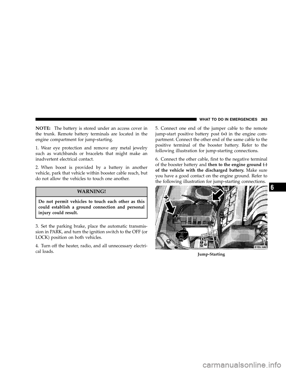
NOTE:The battery is stored under an access cover in
the trunk. Remote battery terminals are located in the
engine compartment for jump-starting.
1. Wear eye protection and remove any metal jewelry
such as watchbands or bracelets that might make an
inadvertent electrical contact.
2. When boost is provided by a battery in another
vehicle, park that vehicle within booster cable reach, but
do not allow the vehicles to touch one another.
WARNING!
Do not permit vehicles to touch each other as this
could establish a ground connection and personal
injury could result.
3. Set the parking brake, place the automatic transmis-
sion in PARK, and turn the ignition switch to the OFF (or
LOCK) position on both vehicles.
4. Turn off the heater, radio, and all unnecessary electri-
cal loads.5. Connect one end of the jumper cable to the remote
jump-start positive battery post(+)in the engine com-
partment. Connect the other end of the same cable to the
positive terminal of the booster battery. Refer to the
following illustration for jump-starting connections.
6. Connect the other cable, first to the negative terminal
of the booster battery andthen to the engine ground (-)
of the vehicle with the discharged battery.Make sure
you have a good contact on the engine ground. Refer to
the following illustration for jump-starting connections.
Jump-Starting
WHAT TO DO IN EMERGENCIES 263
6