2007 CHEVROLET SUBURBAN tow
[x] Cancel search: towPage 192 of 634

Rear Storage Area
Your vehicle may have a storage compartment
located in the rear cargo area of the vehicle in the
driver’s side trim panel.
To open the utility compartment, turn the knobs
and swing the compartment door open. The
compartment door can be removed.
Rear Seat Armrest
Your vehicle may be equipped with a rear seat
armrest. Pull the loop at the top of the armrest
down to access the cupholders.
Cargo Cover
{CAUTION:
An improperly stored cargo cover could
be thrown about the vehicle during a
collision or sudden maneuver. You or
others could be injured. If you remove the
cover, always store it in the proper
storage location. When you put it back,
always be sure that it is securely
reattached.
If your vehicle has a cargo cover, you can use it
to cover items in the cargo area of your vehicle.
To use the cover, do the following:
1. Pull the cover handle toward the rear of the
vehicle.
2. Latch the cover posts into the retaining
sockets on the cargo area trim panels.
192
Page 193 of 634

To return the cover to the retracted position, do
the following:
1. Pull up on the cover handle to release the
cover posts from the retaining sockets.
2. Let the cover move forward to the full retracted
position.
To remove the cover, from a regular wheelbase
model, do the following:
1. Let the cover go all the way into the holder.
2. Then, grasping the driver’s side cover
end cap, push the cover end cap toward the
passenger’s side of the vehicle.
3. Swing the cover rearward and take it out of
the vehicle.To put the cover in the vehicle, do the following:
1. Make sure the cover slot in the holder faces
rearward with the round surface facing down.
2. Then, hold the cover at an angle and place
the cover end cap into the slot in the
passenger’s side trim panel.
3. Move the other end of the cover forward and
hold it next to the driver’s side trim panel slot.
4. Press the end caps in, this will allow the cover
to �t into the trim slot.
5. Lightly pull on the cover holder to make sure
it is secure.
On the extended wheelbase models there are
two cover positions. The slots furthest
forward allow the cover to be used if the third
seat is removed or folded down. The cover
can be installed and removed from either side.
193
Page 195 of 634

4. Lower the system until the middle rollers are
lined up with lower guides. While holding in
the release lever, push the system forward
until all three sets of rollers are on the guides.
5. Release the lever and push the system until
the locator pin reaches the locator hole.
To adjust the system from the lower position to
the upper position, do the following:
1. Squeeze and hold the release lever to retract
the locator pin.
2. Pull the system back and lift until the middle
rollers can be placed into the upper guides.
3. Push the system forward until the front rollers
are lined up with the vertical curved guides.
4. Push down on the rear of the system and
raise the front rollers up the vertical curved
guides.
5. Push the system forward until all three sets of
rollers are resting on the guides and release
the lever to engage the locating pin into
the hole.To utilize the cargo management system as a
table feature, squeeze the release lever and pull
the system towards you until the locator pin
reaches the next hole. The system will extend out
of the vehicle. The liftgate cannot be closed in
this position. Do not operate the vehicle with
liftgate open.
The cargo management system can be removed
from the vehicle. This procedure should be
completed by two people. While squeezing the
release lever, pull the system back until the rollers
clear the guides. To reinstall the system, align
the rollers to the guides, squeeze the release lever
and push into position.
195
Page 200 of 634

Warning Lights, Gages, and Indicators..... 242
Instrument Panel Cluster........................... 243
Speedometer and Odometer...................... 244
Trip Odometer........................................... 244
Tachometer............................................... 244
Safety Belt Reminder Light........................ 244
Passenger Safety Belt Reminder Light....... 245
Airbag Readiness Light............................. 245
Passenger Airbag Status Indicator............. 246
Charging System Light.............................. 248
Voltmeter Gage......................................... 249
Brake System Warning Light..................... 249
Anti-Lock Brake System Warning Light...... 251
StabiliTrak
®Indicator Light......................... 252
Engine Coolant Temperature Gage............ 252
Tire Pressure Light.................................... 253
Malfunction Indicator Lamp........................ 253
Oil Pressure Gage..................................... 256Oil Pressure Light..................................... 257
Security Light............................................ 258
Fog Lamp Light......................................... 258
Cruise Control Light.................................. 258
Highbeam On Light................................... 259
Tow/Haul Mode Light................................ 259
Fuel Gage................................................. 259
Low Fuel Warning Light............................ 260
Driver Information Center (DIC).................. 260
DIC Operation and Displays
(With DIC Buttons)................................. 261
DIC Operation and Displays
(Without DIC Buttons)............................ 267
DIC Warnings and Messages.................... 270
DIC Vehicle Customization
(With DIC Buttons)................................. 280
Section 3 Instrument Panel
200
Page 203 of 634

A. Air Outlets. SeeOutlet Adjustment on
page 238.
B. Turn Signal/Multifunction Lever. SeeTurn
Signal/Multifunction Lever on page 205.
C. Instrument Panel Cluster. SeeInstrument Panel
Cluster on page 243.
D. Hazard Warning Flasher Button. SeeHazard
Warning Flashers on page 204.
E. Shift Lever. SeeAutomatic Transmission
Operation on page 145.
F. Tow/Haul Selector Button (If Equipped). See
Tow/Haul Mode on page 149.
G. Driver Information Center Controls. SeeDriver
Information Center (DIC) on page 260.
H. Audio System. SeeAudio System(s) on
page 290.
I. Exterior Lamps Control. SeeExterior Lamps on
page 215.
J. Dome Lamp Override Button. SeeDome Lamp
Override on page 219.
K. Automatic Transfer Case Control. (If Equipped).
SeeFour-Wheel Drive on page 150.
L. Cruise Control Buttons. SeeCruise Control on
page 211.M. Tilt Wheel Lever. SeeTilt Wheel on page 204.
N. Horn. SeeHorn on page 204.
O. Audio Steering Wheel Controls. SeeAudio
Steering Wheel Controls on page 351.
P. Climate Controls. SeeClimate Control System
on page 227or Dual Automatic Climate
Controls (If Equipped). SeeDual Automatic
Climate Control System on page 231.
Q. Accessory Power Outlets. SeeAccessory
Power Outlet(s) on page 225. Cigarette Lighter
(If Equipped). SeeAshtray(s) and Cigarette
Lighter on page 227.
R. StabiliTrak
®Button (If Equipped). See
StabiliTrak®System on page 363. Pedal Adjust
Button (If Equipped). SeeAdjustable Throttle
and Brake Pedal on page 143. Rear Park Assist
Disable Button (If Equipped). SeeUltrasonic
Rear Parking Assist (URPA) on page 222.
Heated Windshield Washer Fluid Button
(If Equipped). SeeWindshield Washer on
page 209. Power Running Boards Disable
Button (If Equipped). SeePower Running
Boards on page 131.
S. Glove Box. SeeGlove Box on page 190.
203
Page 206 of 634

L(Windshield Washer):SeeWindshield
Washer on page 209.
5(Rear Wiper Delay):SeeRear Window
Wiper/Washer on page 210.
Z(Rear Wiper):SeeRear Window
Wiper/Washer on page 210.
=(Rear Wiper Wash):SeeRear Window
Wiper/Washer on page 210.
Turn and Lane-Change Signals
The turn signal has two upward (for right) and two
downward (for left) positions. These positions allow
you to signal a turn or a lane change.
To signal a turn, move the lever all the way up or
down. When the turn is �nished, the lever will return
automatically.
To signal a lane change, raise or lower the lever for
less than one second until the arrow starts to �ash.
This will cause the turn signals to automatically
�ash three times. It will �ash six times if tow-haul
mode is active. Holding the turn signal lever for
more than one second will cause the turn signals to
�ash until you release the lever. The lever will
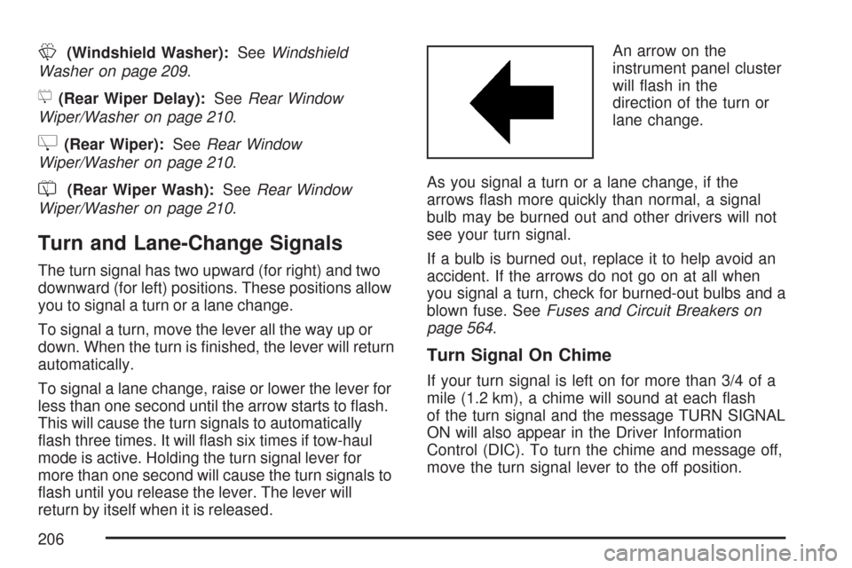
return by itself when it is released.An arrow on the
instrument panel cluster
will �ash in the
direction of the turn or
lane change.
As you signal a turn or a lane change, if the
arrows �ash more quickly than normal, a signal
bulb may be burned out and other drivers will not
see your turn signal.
If a bulb is burned out, replace it to help avoid an
accident. If the arrows do not go on at all when
you signal a turn, check for burned-out bulbs and a
blown fuse. SeeFuses and Circuit Breakers on
page 564.
Turn Signal On Chime
If your turn signal is left on for more than 3/4 of a
mile (1.2 km), a chime will sound at each �ash
of the turn signal and the message TURN SIGNAL
ON will also appear in the Driver Information
Control (DIC). To turn the chime and message off,
move the turn signal lever to the off position.
206
Page 207 of 634

Headlamp High/Low-Beam Changer
53(Headlamp High/Low Beam Changer):
To change the headlamps from low to high beam,
push the lever toward the instrument panel. To
return to low-beam headlamps, pull the
multifunction lever toward you. Then release it.
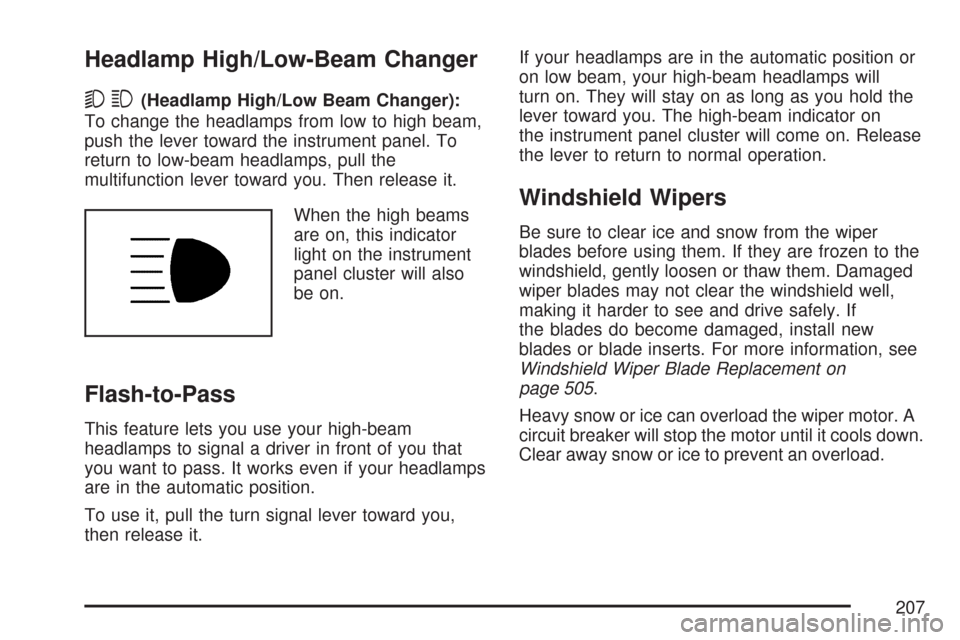
When the high beams
are on, this indicator
light on the instrument
panel cluster will also
be on.
Flash-to-Pass
This feature lets you use your high-beam
headlamps to signal a driver in front of you that
you want to pass. It works even if your headlamps
are in the automatic position.
To use it, pull the turn signal lever toward you,
then release it.If your headlamps are in the automatic position or
on low beam, your high-beam headlamps will
turn on. They will stay on as long as you hold the
lever toward you. The high-beam indicator on
the instrument panel cluster will come on. Release
the lever to return to normal operation.
Windshield Wipers
Be sure to clear ice and snow from the wiper
blades before using them. If they are frozen to the
windshield, gently loosen or thaw them. Damaged
wiper blades may not clear the windshield well,
making it harder to see and drive safely. If
the blades do become damaged, install new
blades or blade inserts. For more information, see
Windshield Wiper Blade Replacement on
page 505.
Heavy snow or ice can overload the wiper motor. A
circuit breaker will stop the motor until it cools down.
Clear away snow or ice to prevent an overload.
207
Page 228 of 634

To change the current mode, select one of the
following:
H(Vent):This mode directs air to the instrument
panel outlets.
)(Bi-Level):This mode directs half of the air to
the instrument panel outlets and to the �oor
outlets. The �ow can be divided between vent and
�oor outlets depending upon where the knob is
placed between the settings. A little air is directed
towards the windshield and side window outlets.
Cooler air is directed to the upper outlets and
warmer air to the �oor outlets.
6(Floor):This mode directs most of the air to
the �oor outlets, with some of the air directed
to the windshield, side window outlets, and second
row �oor outlets. In this mode, the system will
automatically select outside air. Recirculation
cannot be selected when in Floor Mode.The right knob can also be used to select defog or
defrost mode. For more information, see
“Defogging and Defrosting” later in this section.
By positioning the right knob between two modes,
a combination of those two modes is selected.
The air conditioning compressor will be on unless
the outside temperature is close to freezing.
9(Fan):Turn the left knob clockwise or
counterclockwise to increase or decrease the fan
speed. Turn the knob all the way counterclockwise
to turn the front system off.
?(Recirculation):Press this button to turn the
recirculation mode on. When the button is pressed,
an indicator light will come on.
This mode keeps outside air from entering the
vehicle. It can be used to reduce outside air and
prevent odors from entering your vehicle.
Recirculation may also help cool the air inside your
vehicle more quickly once the temperature inside
the vehicle is less than the outside temperature.
228