Page 473 of 684

4. Adjust the Trailer Gain by using the gain
adjustment (+ / -) buttons on the Trailer
Brake Control Panel.
5. Drive the vehicle with the trailer attached on a
level road surface representative of the towing
condition and free of traffic at about 20 to
25 mph (32 to 40 km/h) and fully apply
the Manual Trailer Brake Apply lever.
Adjusting trailer gain at speeds lower than
20 to 25 mph (32 to 40 km/h) may result in an
incorrect gain setting.
6. Adjust the Trailer Gain to just below the point
of trailer wheel lock-up, indicated by trailer
wheel squeal or puffs of tire smoke when
a trailer wheel locks.
Trailer wheel lock-up may not occur if towing
a heavily loaded trailer. In this case, adjust
the Trailer Gain to the highest allowable
setting for the towing condition.
7. Re-adjust Trailer Gain any time vehicle
loading, trailer loading or road surface
conditions change or if you notice trailer wheel
lock-up at any time while you are towing.Other ITBC Related DIC Messages
In addition to displaying TRAILER GAIN and
TRAILER OUTPUT through the DIC, trailer
connection and ITBC system status is displayed in
the DIC.
TRAILER CONNECTED – This message will be
brie�y displayed when a trailer with electric brakes
is �rst connected to the vehicle. This message
will automatically turn off in about ten seconds.
The driver can also acknowledge this message
before it automatically turns off.
CHECK TRAILER WIRING – This message will be
displayed if:
1. The ITBC system �rst determines connection
to a trailer with electric brakes and then the
trailer harness becomes disconnected
from the vehicle.
If the disconnect occurs while the vehicle is
stationary, this message will automatically turn
off in about thirty seconds. This message
will also turn off if the driver acknowledges this
message off or if the trailer harness is
re-connected.
473
Page 474 of 684

If the disconnect occurs while the vehicle is
moving, this message will continue until the
ignition is turned off. This message will also
turn off if the driver acknowledges this message
off or if the trailer harness is re-connected.
2. There is an electrical fault in the wiring to the
electric trailer brakes. This message will
continue as long as there is an electrical fault in
the trailer wiring. This message will also turn off
if the driver acknowledges this message off.
To determine if the electrical fault is on the vehicle
side or trailer side of the trailer wiring harness
connection, do the following:
1. Disconnect the trailer wiring harness from the
vehicle.
2. Turn the ignition OFF.
3. Wait ten seconds, then turn the ignition back
to RUN.
4. If the CHECK TRAILER WIRING message
re-appears, the electrical fault is on the
vehicle side.
If the CHECK TRAILER WIRING message
only re-appears when you connect the trailer
wiring harness to the vehicle, the electrical
fault is on the trailer side.SERVICE TRAILER BRAKE SYSTEM – This
message will be displayed when there is a problem
with the ITBC system. If this message persists over
multiple ignition cycles there is problem with the
ITBC system. Take your vehicle to an authorized
GM dealer to have the ITBC system diagnosed and
repaired.
If either the CHECK TRAILER WIRING or
SERVICE TRAILER BRAKE SYSTEM message is
displayed while you are driving your vehicle, you no
longer have power available to your trailer brakes.
When traffic conditions allow, carefully pull your
vehicle over to the side of the road and turn the
ignition off. Check the wiring connection to the
trailer and turn the ignition back on. If either of these
messages continues, either your vehicle or your
trailer needs service.
An authorized GM dealer may be able to diagnose
and repair problems with your trailer. However, any
diagnosis and repair of your trailer is not covered
under your GM Warranty. Please contact your
trailer dealer for assistance with trailer repairs and
trailer warranty information.
474
Page 480 of 684

Maintenance When Trailer Towing
Your vehicle will need service more often when
you’re pulling a trailer. SeeScheduled
Maintenance (Gasoline Engine) on page 627for
more information. Things that are especially
important in trailer operation are automatic
transmission �uid (don’t over�ll), engine oil, axle
lubricant, belt, cooling system and brake system.
Each of these is covered in this manual, and
the Index will help you �nd them quickly. If you’re
trailering, it’s a good idea to review these
sections before you start your trip.
Check periodically to see that all hitch nuts and
bolts are tight.
Trailer Wiring Harness
Your vehicle is equipped with one of the following
wiring harnesses for towing a trailer or hauling
a slide-in camper.
Basic Trailer Wiring
All regular, extended cab and crew cab pickups
have a seven-wire trailer towing harness.
For vehicles not equipped with heavy duty
trailering, the harness is clipped to the vehicle’s
frame behind the spare tire mount. The harness
requires the installation of a trailer connector,
which is available through your dealer.
If you need to tow a light-duty trailer with a
standard four-way round pin connector, you can
also get an adapter from your dealer.
480
Page 481 of 684

Heavy-DutyTrailer Wiring Harness
Package
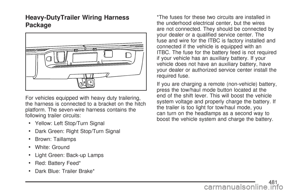
For vehicles equipped with heavy duty trailering,
the harness is connected to a bracket on the hitch
platform. The seven-wire harness contains the
following trailer circuits:
Yellow: Left Stop/Turn Signal
Dark Green: Right Stop/Turn Signal
Brown: Taillamps
White: Ground
Light Green: Back-up Lamps
Red: Battery Feed*
Dark Blue: Trailer Brake**The fuses for these two circuits are installed in
the underhood electrical center, but the wires
are not connected. They should be connected by
your dealer or a quali�ed service center. The
fuse and wire for the ITBC is factory installed and
connected if the vehicle is equipped with an
ITBC. The fuse for the battery feed is not required
if your vehicle has an auxiliary battery. If your
vehicle does not have an auxiliary battery, have
your dealer or authorized service center install the
required fuse.
If you are charging a remote (non-vehicle) battery,
press the tow/haul mode button located at the
end of the shift lever. This will boost the vehicle
system voltage and properly charge the battery. If
the trailer is too light for tow/haul mode, you
can turn on the headlamps as a second way to
boost the vehicle system and charge the battery.
481
Page 482 of 684
Camper/Fifth-Wheel Trailer Wiring Package
The seven-wire camper harness is located
under the front edge of the pickup box on the
driver’s side of the vehicle, attached to the frame
bracket. A connector will have to be added to
the wiring harness which connects to the camper.
The harness contains the following camper/trailer
circuits:
Yellow: Left Stop/Turn Signal
Dark Green: Right Stop/Turn Signal
Brown: Taillamps
White: Ground
Light Green: Back-up Lamps
Red: Battery Feed
Dark Blue: Trailer BrakeIf your vehicle is equipped with the “Heavy-Duty
Trailering” option, please refer to “Heavy-Duty
Trailer Wiring Package” earlier in this section.
When the camper-wiring harness is ordered
without the heavy-duty trailering package, an
eight-wire harness with a seven-pin connector is
located at the rear of the vehicle and is tied to the
vehicle’s frame.
482
Page 483 of 684
Electric Brake Control Wiring
Provisions
These wiring provisions are included with your
vehicle as part of the trailer wiring package. These
provisions are for an electric brake controller.
The instrument panel contains blunt cut wires near
the data link connector for the trailer brake
controller.The harness contains the following wires:
Dark Blue: Brake Signal to Trailer Connector
Red/Black: Battery
Light Blue/White: Brake Switch
White: Ground
It should be installed by your dealer or a quali�ed
service center.
If your vehicle is equipped with an ITBC, the blunt
cuts exist, but are not connected further in the
harness. If you install an aftermarket trailer brake
controller, the ITBC must be disconnected. Do
not power both ITBC and aftermarket controllers to
control the trailer brakes at the same time.
483
Page 612 of 684
Fuses and Circuit Breakers
The wiring circuits in your vehicle are protected
from short circuits by a combination of fuses,
circuit breakers and fusible thermal links.
This greatly reduces the chance of �res caused by
electrical problems.
Look at the silver-colored band inside the fuse. If
the band is broken or melted, replace the fuse.
Be sure you replace a bad fuse with a new one of
the identical size and rating.
If you ever have a problem on the road and do not
have a spare fuse, you can borrow one that has
the same amperage. Just pick some feature
of your vehicle that you can get along without, like
the radio or cigarette lighter, and use its fuse if
it is the correct amperage. Replace it as soon as
you can.
Instrument Panel Fuse Block
The instrument panel
fuse block access door
is located on the
driver’s side edge of the
instrument panel.
Pull off the cover to access the fuse block.
612