Page 46 of 166

Replacement and extra
keysYou can obtain replacement/extra
keys only through an authorised
BMW Motorrad dealer. The keys
are part of an integrated secur-
ity system, so the dealer is un-
der an obligation to check the
legitimacy of all applications for
replacement/extra keys. If you
want to have a lost key barred,
you have to bring with you all
the other keys that belong to
the motorcycle. A key that has
been barred can subsequently be
cleared and reactivated for use.ClockSetting clock
Attempting to set the clock
while riding the motorcycle
can lead to accidents.
Set the clock only when the mo-
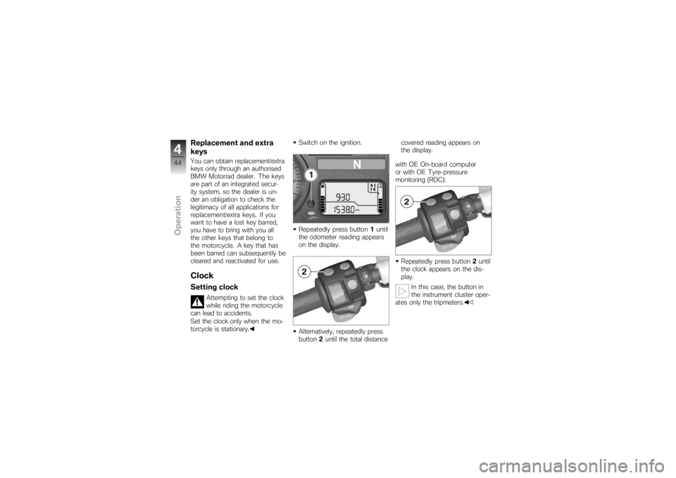
torcycle is stationary. Switch on the ignition.
Repeatedly press button
1until
the odometer reading appears
on the display.
Alternatively, repeatedly press
button 2until the total distance covered reading appears on
the display.
with OE On-board computer
or with OE Tyre-pressure
monitoring (RDC):
Repeatedly press button 2until
the clock appears on the dis-
play.
In this case, the button in
the instrument cluster oper-
ates only the tripmeters.
444zOperation
Page 67 of 166
Push down firmly on the seat,
applying pressure to the point
above the latch.
The seat engages with an aud-
ible click.Helmet holderSecuring helmet to
motorcycleRemove the seat ( 63)Use the wire rope available as
an optional accessory to se-
cure the helmet to one of the
helmet holders
1or 2. The helmet catch can
scratch the panelling.
Make sure the lock is out of the
way when you hook the helmet
into position.
Pass the steel cable through
the helmet and push it onto
the helmet holder.
Install the seat ( 64)
465zOperation
Page 72 of 166

ChecklistUse the following checklist to
check important functions, set-
tings and wear limits before you
ride off.Brakes
Brake-fluid levels, front and rear
Clutch
Clutch fluid level
Shock absorber setting and
spring preload
Tyre-tread depth and tyre
pressures
Cases correctly installed and
luggage secured
At regular intervals: Engine oil level (every refuelling
stop)
Brake-pad wear (every third
refuelling stop)
StartingSide standYou cannot start the motorcycle
with the side stand extended and
a gear engaged. The engine will
switch itself off if you start it with
the gearbox in neutral and then
engage a gear before retracting
the side stand.GearboxYou can start the engine when
the gearbox is in neutral or if you
pull the clutch with a gear en-
gaged. Do not pull the clutch un-
til after you have switched on the
ignition, as otherwise the engine
will refuse to start. When the
gearbox is in neutral, the green
neutral telltale light is on and the
gear indicator in the multifunction
display shows N.
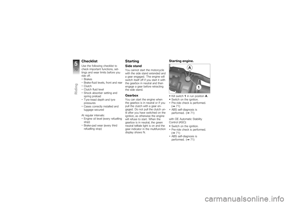
Starting engine.Kill switch 1in run position A.
Switch on the ignition.
Pre-ride check is performed.
( 71)
ABS self-diagnosis is
performed. ( 71)
with OE Automatic Stability
Control (ASC): Switch on the ignition.
Pre-ride check is performed.
( 71)
ABS self-diagnosis is
performed. ( 71)
570zRiding
Page 93 of 166
Pull the grey release lever
(OPEN) up again.
Pull case lid2out of the retain-
er.Closing casesPress catches 1of the case lid
into retainers 2.
The catches engage with an
audible click.
Press the catches on the lock
straps into retainers 2.
The catches engage with an
audible click.
Check that the catches are
locked securely into place.
Adjusting case volumeClose the case lid.
Turn the lock strap
buckles 1of the lock straps
out.
Pull the lock straps up and out.
This expands the case to max-
imum volume. Close the lock straps.
Press the lock straps against
the case body.
The case volume adapts to the
contents.
791zAccessories
Page 95 of 166
Pull the black release lever
(RELEASE) up.
Press the case into top hold-
er3.
Push the black release lever
(RELEASE) down.
The case is locked into place.
Lock the case.
Check that it is correctly en-
gaged.Secure attachmentIf a case wobbles or is difficult
to fit, it has to be adapted to the
gap between the top and bottom
holders. The bottom bracket on the case can be moved up or
down for this purpose.
Adapting caseOpen the case.
Remove screws
1.
Adjust the height of the holder.
Tighten screws 1.
Breakdown assistance
kit
OA
UseThe stowage space for the
breakdown assistance kit is under
the left side panel.
See the description enclosed
with the breakdown assistance
kit for instructions detailing the
procedure and for safety informa-
tion.Removing breakdown
assistance kitMake sure the ground is level
and firm and place the motor-
cycle on its stand.
Remove the seat ( 63)
793zAccessories
Page 108 of 166
Motorrad dealer or specialist
workshop to the fact that the
wheel is fitted with an RDC
sensor.Remove the front wheelPlace the motorcycle on an
auxiliary stand; BMW Motorrad
recommends the BMW Motor-
rad rear-wheel stand.
Install the rear-wheel stand
( 114)
with OA Centre stand:
Make sure the ground is level
and firm and place the motor-
cycle on its centre stand. Remove screws
1on left and
right.
Pull the front mudguard for-
ward to remove. Once the calipers have
been removed, there is
a risk of the brake pads being
pressed together to the extent
that they cannot be slipped back
over the brake disc on reas-
sembly.
Do not operate the handbrake
lever when the brake calipers
have been removed.
Remove securing screws 3of
the brake calipers on left and
right.
8106zMaintenance
Page 110 of 166

correct sensor ring is installed.
Install only the sensor ring that
matches the motorcycle's con-
struction status.Threaded fasteners not
tightened to the specified
torque can work loose or their
threads can suffer damage.
Always have the security of the
fasteners checked by a specialist
workshop, preferably an author-
ised BMW Motorrad dealer.
The front wheel must be
installed right way round to
rotate in the correct direction.
Note the direction-of-rotation ar-
rows on the tyre or the wheel
rim.
There is a risk of damaging
parts of the front brake,
particularly the BMW Motorrad
Integral ABS, in the course of the
procedure described below.
Take care not to damage the
brake system, in particular the ABS sensor with cable and the
ABS sensor ring.
Roll the front wheel into posi-
tion between the front forks.
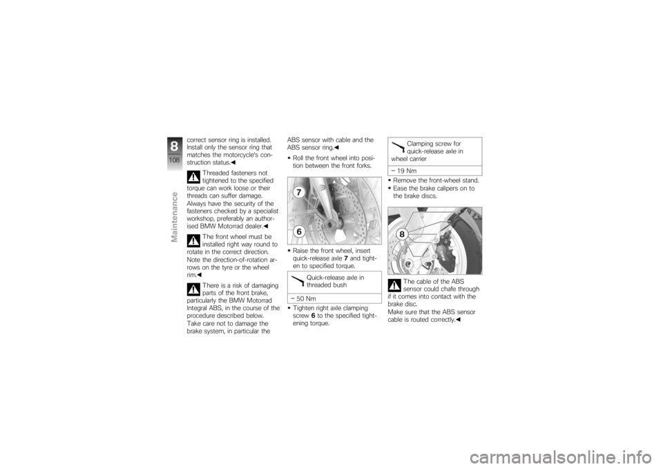
Raise the front wheel, insert
quick-release axle 7and tight-
en to specified torque.
Quick-release axle in
threaded bush
50 Nm
Tighten right axle clamping
screw 6to the specified tight-
ening torque. Clamping screw for
quick-release axle in
wheel carrier
19 Nm
Remove the front-wheel stand.
Ease the brake calipers on to
the brake discs.
The cable of the ABS
sensor could chafe through
if it comes into contact with the
brake disc.
Make sure that the ABS sensor
cable is routed correctly.
8108zMaintenance
Page 111 of 166
Carefully route the ABS sensor
cable. Make sure that the ABS
sensor cable is clipped into
holders8.
Install securing screws 3on
left and right and tighten to
specified tightening torque.
Front brake caliper to
wheel carrier
30 Nm
Remove the adhesive tape
from the wheel rim.
Firmly pull the handbrake lever
until the pressure point is per- ceptible, and repeat this opera-
tion several times.
Install the front mudguard and
install screws
1on left and
right.
Remove the rear wheel stand,
if installed beforehand.
Removing rear wheelPlace the motorcycle on an
auxiliary stand; BMW Motorrad
recommends the BMW Motor-
rad rear-wheel stand.
Install the rear-wheel stand
( 114) with OA Centre stand:
Make sure the ground is level
and firm and place the motor-
cycle on its centre stand.
Remove screw 1from silencer
cover 2.
Pull the cover to the rear to
remove.
8109zMaintenance