Page 352 of 479

Your vehicle is equipped with disc
brakes at all f our wheels. A power
assist helps reduce the ef f ort needed
on the brake pedal. Emergency
Brake Assist System increases the
stopping f orce when you depress the
brake pedal hard in an emergency
situation. The anti-lock brake system
(ABS) helps you retain steering
control when braking very hard.
Resting your f oot on the brake pedal
applies the brakes slightly. This
builds up heat, and reduces brake
ef f ectiveness and brake pad lif e. In
addition, f uel economy can be
reduced. It also keeps your brake
lights on all the time, conf using
drivers behind you.The hydraulic system that operates
the brakes has two separate circuits.
Each circuit works diagonally across
the vehicle (the lef t-f ront brake is
connected with the right-rear brake,
etc.). If one circuit should develop a
problem, you will still have braking
at two wheels.
All f our brakes have audible brake
wear indicators.
If the brake pads need replacing, you
will hear a distinctive, metallic
screeching sound when you apply
the brake pedal. If you do not have
the brake pads replaced, they will
screech all the time. It is normal f or
the brakes to occasionally squeal or
squeak when you apply them.
Constant application of the brakes
when going down a long hill builds
up heat and reduces their ef f ective-
ness. Use the engine to assist the
brakes by taking your f oot of f the
accelerator and downshif ting to a
lower gear.
Check the brakes after driving
through deep water. Apply the
brakes moderately to see if they f eel
normal. If not, apply them gently and
f requently until they do. Be extra
cautious in your driving.
Braking System
Braking System Design
Brake Wear Indicators
348
�����—�����—�����y�
�������������y���
�(�)�-�������y���������y
Page 358 of 479
If there is a problem with the active
damper system, the active damper
system shuts down and the active
damper system indicator on the
instrument panel comes on.
You will also see the ‘‘CHECK ADS
SYSTEM’’ message appears on the
multi-inf ormation display.
When comf ort mode is selected, the
green indicator in the button comes
ON, and the message ‘‘COMFORT’’
will appear on the multi-inf ormation
display f or f ive seconds.
When sport mode is selected, the
green indicator in the button goes of f ,
and the message ‘‘SPORT’’ will
appear on the multi-inf ormation
display f or f ive seconds.
A ctive Damper System
Active Damper System
Indicator
354
�����—�����—�����y�
�������������y���
�(�)�-�������y���������y
Page 361 of 479

Park the vehicle on level ground.
Measure and record the distance
from the ground to the bottom of
the trailer hitch.
Connect the fully loaded trailer to
the hitch.
Measure again from the ground to
the same spot on the bottom of the
hitch.
Subtract the second measurement
from the first measurement, then
refer to the following table.
Add
the weight of your trailer (as
quoted by the manufacturer) with
everything in or on the trailer. Then
check the tables on page to
make sure you do not exceed the
limit f or your conditions. To help ensure a saf e drive to a scale,
or if you cannot get to a public scale,
we recommend that you estimate
your total trailer weight and tongue
load as described next. Thebestwaytoconfirmthatall
loads are within limits is to check
them at a public scale. For public
scales in your area, check your local
phone book, or contact your trailer
dealer or rental agency for
assistance.
Estimated
tongue load is:
150 lbs (68 kg)
250 lbs (114 kg)
350 lbs (159 kg)
450 lbs (205 kg) Estimated
tongue load is:
150 lbs (68 kg)
250 lbs (114 kg)
350 lbs (159 kg)
450 lbs (205 kg)
If thedifferenceismorethan1½
inch, you have too much load on the
tongue. Redistribute the load or
remove cargo as needed. If the
dif f erence is:
13/32’’
11/16’’
31/32’’11/4’’
If the
dif f erence is:
1/2’’
27/32’’
1 5/32’’ 11/2’’
1.
2.
3.
4.
5.
358
U.S. Sport Packages and Canadian Elite models
MDX and Technology Packages models
Towing a Trailer
To Estimate the Tongue Load
To Estimate the Total Trailer WeightEstimating Loads
Driving
357
�����—�����—�����y�
�������������y���
�(�)�-�������y���������y
Page 369 of 479
. You will al")
�µ
�µ
�µ
�µ
�µ
�µ
CONTINUED
If the autom atic transmission fluid
temperature increases and exceeds
the speci fied limit, the A/T
temperature indicator comes on (see
page ). You will also see a ‘‘A/T
TEMP HIGH’’ message on the multi-
information display.
Make turnsmoreslowlyandwider
than normal. The trailer tracks a
smaller arc than your vehicle, and it
canhitorrunoversomethingthe
vehicle misses.
Allow more time and distance for
braking. Do not brake or turn
suddenly as this could cause the
trailer to jackknife or turn over.
When
driving uphill and downhill,
use the Sequential SportShift mode
to provide the proper engine power
and engine braking on each gear.
Select fourth, third, second, or first
gear; dep ending on the vehicle
speeds and road condition. Do not
use fifth gear. The recommended
speed range for each gear position is
showninthetable.
Gear position
1
2
3
4 Speed
range
019mph
(0 30 km/h)
19 31 mph
(30 50 km/h)
31 41 mph
(50 65 km/h)
over 41 mph
(over 65 km/h)
Drive
slower than normal in all
driving situations, and obey posted
speed limits for vehicles with trailers.
Use D position when towing a trailer
on level roads. D is the proper shif t
lever position to use when towing a
trailer in hilly terrain. (See ‘‘ ’’onthenextpagefor
additional gear information.)
When towing a f ixed-sided trailer (e.
g., camper), do not exceed 55 mph
(88 km/h). At higher speeds, the
trailer may sway or affect vehicle
handling. 68
3
Towing a Trailer
Making T urns and Braking
T owing Speeds and Gears
Driving
on Hills
Driving
365
�����—�����—�����y�
�������������y���
�(�)�-�������y���������y
Page 382 of 479

�Ý�Û�Ý�Û
If the indicated required service is
not done and the remaining engine
oil lif e becomes 0 %, the multi-
inf ormation display will show a
‘‘SERVICE PAST DUE’’ message,
thetotalmileageaftertheremaining
oillifebecame0%,andthe
maintenance item code(s). This message is displayed when you
drive over 10 miles (f or U.S. models)
or 10 km (f or Canadian models)
after seeing the 0 % message.
Immediately have the service
perf ormed, and make sure to reset
the display as previously described.
The message will be canceled if the
or buttononthesteeringwheel
is pressed. Press the or button
to see the message again.
When you press the SEL/RESET
button to select the engine oil lif e,
the message ‘‘SERVICE’’, along with
the maintenance item code and the
total negative mileage af ter the oil
lif e became 0 %, will be displayed on
the lower part of the multi-
inf ormation display.
Maintenance Minder
378
MAINTENANCE CODE
CANADA U.S.
TOTAL PAST DUE MILEAGE
TOTAL PAST DUE MILEAGE
U.S.
CANADA
�����—�����—�����y�
������
��
���y���
�(�)�-�������y���������y
Page 383 of 479

�Û�Ý
All
the maintenance items displayed
in the multi-information display are
in code.
For an explanation of the
maintenance codes, see page .Your dealer will reset the display
af ter completing the required
maintenance service. You will see
‘‘OIL LIFE 100%’’ on the display the
next time you turn the ignition
switch to the ON (II) position.
If maintenance service is done by
someone other than your dealer,
reset the maintenance minder as
f ollows:
Turn the ignition switch to the ON
(II) position.
If the engine oil lif e is not
displayed, press the SEL/RESET
buttononthesteeringwheel
repeatedly the multi-information
display shows blank, SH-AWD and
tire pressure. Select ‘‘RESET’’ by pressing the
INFO ( / ) button, then press
the SEL/RESET button to reset
the engine oil lif e display. The
maintenance item code(s) will
disappear, and the engine oil lif e
will reset to ‘‘100.’’ If you want to
cancel the oil lif e reset mode,
select ‘‘CANCEL.’’
Press and hold the SEL/RESET
button on the steering wheel f or more than 10 seconds. The
remaining engine oil lif e reset
mode will be shown on the multi-
inf ormation display.
1.
2.
3. 4.
382
Maintenance Minder
Maintenance Main Items and Sub
Items Resetting the Engine Oil Lif e
Display
Maint enance
379
MAINTENANCE
MAIN ITEM
MAINTENANCE
MAIN ITEM MAINTENANCE
SUB ITEMS
MAINTENANCE
SUB ITEMS
�����—�����—�����y�
������
������y���
�(�)�-�������y���������y
Page 422 of 479

Use the compact spare tire as a
temporary replacement only. Get
your regular tire repaired or replaced,
and put it back on your vehicle as
soon as you can.
Check the inf lation pressure of the
compact spare tire every time you
check the other tires. It should be
inf lated to:
Follow these precautions:Do not mount snow chains on a
compact spare.
Do not use the compact spare tire
if you are towing a trailer.
Do not use your compact spare
tire on another vehicle unless it is
thesamemakeandmodel.
Replace the tire when you can see
the tread wear indicator bars. The
replacement should be the same size
and design tire, mounted on the
same wheel. The spare tire is not
designed to be mounted on a regular
wheel, and the spare wheel is not
designed f or mounting a regular tire.
Never exceed 50 mph (80 km/h).
This tire gives a harsher ride and
less traction on some road
surf aces. Use greater caution
while driving. The low tire pressure indicator
stays on when you are driving with
thecompactsparetire.TheTPMS
indicator may also come on after
several miles (kilometers) driving.
Compact Spare Tire
418
INDICATOR LOCATION MARK
TREAD WEAR INDICATOR BAR
60 psi (420 kPa , 4.2 kgf/cm)
�����—�����—�����y�
�������������y���
�(�)�-�������y���������y
Page 445 of 479
�µ
�µ
�µ
�µ
�µ
�Î
�Î
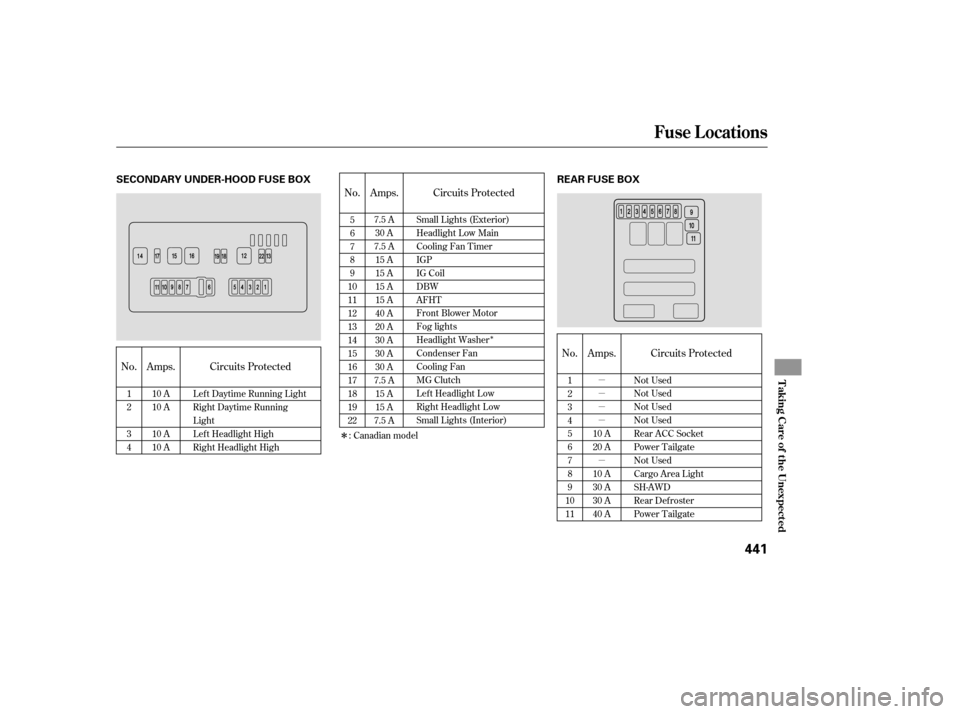
No. Amps. Circuits Protected No. Amps.
No. Circuits ProtectedAmps.
Circuits Protected
1
2
3
4
10 A
10 A
10 A
10 A Lef t Daytime Running Light
Right Daytime Running
Light
Left Headlight High
Right Headlight High 5
6
7
8
9
10
11
12
13
14
15
16
17
18
19
22 7.5 A
30 A
7.5 A 15 A
15 A
15 A
15 A
40 A
20 A
30 A
30 A
30 A
7.5 A 15 A
15 A
7.5 A 1
2
3
4
5
6
7
8
9
10
11 Not Used
Not Used
Not Used
Not Used
Rear ACC Socket
Power Tailgate
Not Used
Cargo Area Light
SH-AWD
Rear Defroster
Power Tailgate
10 A
20 A
10 A
30 A
30 A
40 A
Small Lights (Exterior)
Headlight Low Main
Cooling Fan Timer
IGP
IG Coil
DBW
AFHT
Front Blower Motor
Fog lights
Headlight Washer
Condenser Fan
Cooling Fan
MG Clutch
Left Headlight Low
Right Headlight Low
Small Lights (Interior)
: Canadian model
Fuse Locations
T aking Care of t he Unexpect ed
441
SECONDARY UNDER-HOOD FUSE BOX REAR FUSE BOX
�����—�����—�����y�
�������������y���
�(�)�-�������y���������y