Page 160 of 390

3 - 15
INSP
ADJ
FRONT FORK INSPECTION
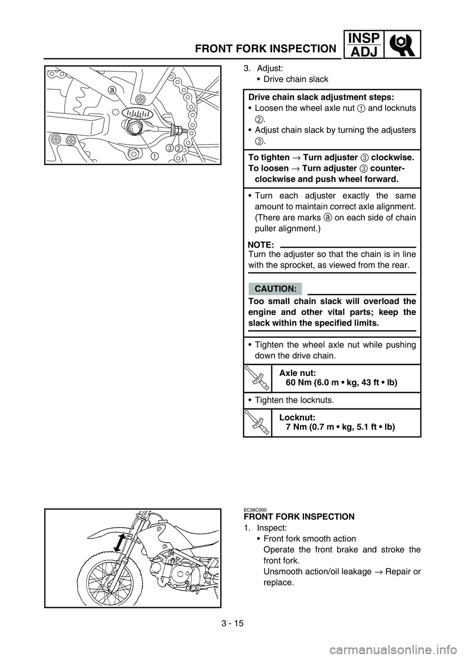
3. Adjust:
Drive chain slack
Drive chain slack adjustment steps:
Loosen the wheel axle nut 1 and locknuts
2.
Adjust chain slack by turning the adjusters
3.
To tighten
→ Turn adjuster
3 clockwise.
To loosen
→ Turn adjuster
3 counter-
clockwise and push wheel forward.
Turn each adjuster exactly the same
amount to maintain correct axle alignment.
(There are marks a on each side of chain
puller alignment.)
NOTE:
Turn the adjuster so that the chain is in line
with the sprocket, as viewed from the rear.
CAUTION:
Too small chain slack will overload the
engine and other vital parts; keep the
slack within the specified limits.
Tighten the wheel axle nut while pushing
down the drive chain.
T R..
Axle nut:
60 Nm (6.0 m kg, 43 ft lb)
Tighten the locknuts.
T R..
Locknut:
7 Nm (0.7 m kg, 5.1 ft lb)
13 a2
EC36C000
FRONT FORK INSPECTION
1. Inspect:
Front fork smooth action
Operate the front brake and stroke the
front fork.
Unsmooth action/oil leakage → Repair or
replace.
Page 174 of 390
3 - 22
INSP
ADJ
LUBRICATION
LUBRICATION
To ensure smooth operation of all compo-
nents, lubricate your machine during setup,
after break-in, and after every race.
1All control cable
2Brake lever pivot
3Shift pedal pivot
4Footrest pivot
5Throttle-to-handlebar contact
6Drive chain
7Tube guide cable winding portion
8Throttle cable end
9Brake cable endÈUse Yamaha cable lube or equivalent on these
areas.
ÉUse SAE 10W-30 motor oil or suitable chain
lubricants.
ÊLubricate the following areas with high quality,
lightweight lithium-soap base grease.
AAA
AAB
CC
78
Page 296 of 390
5 - 1
CHAS
EC500000
CHASSIS
FRONT WHEEL AND REAR WHEEL
FRONT WHEEL AND FRONT BRAKE
Extent of removal:
1 Front wheel removal
2 Wheel bearing removal
3 Brake shoe plate assembly removal and disassembly
Extent of removal Order Part name Q’ty Remarks
FRONT WHEEL REMOVAL
WARNING
Support the machine securely so
there is no danger of it falling over. Preparation for removal Hold the machine by placing the
suitable stand under the engine.
1 Bolt (brake cable holder) 1 Only loosening.
2 Brake cable 1 Disconnect at the lever side.
3 Wheel axle nut 1
4 Front wheel axle 1
5 Front wheel 1
6 Collar set 1
7 Brake shoe plate assembly 1
8 Oil seal 1
9 Bearing 2 Refer to “REMOVAL POINTS”.
2
13
3
FRONT WHEEL AND REAR WHEEL
Page 298 of 390
5 - 2
CHAS
Extent of removal Order Part name Q’ty Remarks
10 Brake shoe 2
11 Brake camshaft lever 1
12 Brake camshaft 1
3
FRONT WHEEL AND REAR WHEEL
Page 300 of 390
5 - 3
CHASFRONT WHEEL AND REAR WHEEL
REAR WHEEL AND REAR BRAKE
Extent of removal:
1 Rear wheel removal
2 Wheel bearing removal
3 Brake shoe plate assembly removal and disassembly
Extent of removal Order Part name Q’ty Remarks
REAR WHEEL REMOVAL
WARNING
Support the machine securely so
there is no danger of it falling over. Preparation for removal Hold the machine by placing the
suitable stand under the engine.
1 Brake rod 1
2Cotter pin 1
3 Nut (tension bar) 1
4 Bolt (tension bar) 1
5 Wheel axle nut 1
6 Rear wheel axle 1
7 Drive chain puller 2
8 Rear wheel 1
9 Collar (right) 1
10 Brake shoe plate assembly 1
2
1
3
Page 302 of 390
5 - 4
CHASFRONT WHEEL AND REAR WHEEL
Extent of removal Order Part name Q’ty Remarks
11 Collar (left) 1
12 Wheel drive hub assembly 1
13 Bearing 2 Refer to “REMOVAL POINTS”.
14 Brake shoe 2
15 Brake camshaft lever 1
16 Brake camshaft 1
2
3
Page 304 of 390
5 - 5
CHASFRONT WHEEL AND REAR WHEEL
EC593000
REMOVAL POINTS
EC513201
Wheel bearing (if necessary)
1. Remove:
Bearing 1
NOTE:
Remove the bearing using a general bearing
puller 2.1
1
2
1
EC594000
INSPECTION
EC514100
Wheel
1. Measure:
Wheel runout
Out of limit → Repair/replace.
Brake lining
1. Inspect:
Brake shoe lining surface
Glazed areas → Polish.
Use coarse sand paper.
NOTE:
After polishing, wipe the polished particles with
a cloth.
Wheel runout limit:
Radial
1: 2.0 mm (0.08 in)
Lateral
2: 2.0 mm (0.08 in)
2. Measure:
Brake shoe lining thickness
Out of specification → Replace.
NOTE:
Replace the brake shoes and springs as a set
if either is worn to the limit.
Brake shoe lining thickness
a:
Standard:
Front: 3.0 mm (0.12 in)
Rear: 4.0 mm (0.16 in)
Limit:
2.0 mm (0.08 in)
Page 306 of 390
5 - 6
CHAS
ASSEMBLY AND INSTALLATION
1. Install:
Brake camshaft lever 1
NOTE:
Install the brake camshaft lever in relation to
the punch mark a as shown.
ÈFront
ÉRear
1
1a
È
a 1
1
É
T R..10 Nm (1.0 m · kg, 7.2 ft · lb)
2. Install:
Springs 1
Brake shoes 2
NOTE:
Apply the lithium soap base grease on the
pivot pin.
WARNING
Do not apply grease to the brake shoe lin-
ings.
New
FRONT WHEEL AND REAR WHEEL