Page 144 of 390

3 - 7
INSP
ADJ
ENGINE OIL REPLACEMENT
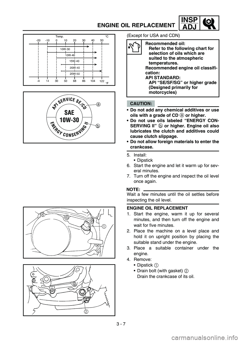
(Except for USA and CDN)
CAUTION:
Do not add any chemical additives or use
oils with a grade of CD
a or higher.
Do not use oils labeled “ENERGY CON-
SERVING II”
b or higher. Engine oil also
lubricates the clutch and additives could
cause clutch slippage.
Do not allow foreign materials to enter the
crankcase.
5. Install:
Dipstick
6. Start the engine and let it warm up for sev-
eral minutes.
7. Turn off the engine and inspect the oil level
once again.
NOTE:
Wait a few minutes until the oil settles before
inspecting the oil level.
Recommended oil:
Refer to the following chart for
selection of oils which are
suited to the atmospheric
temperatures.
Recommended engine oil classifi-
cation:
API STANDARD:
API “SE/SF/SG” or higher grade
(Designed primarily for
motorcycles)
a
b
ENGINE OIL REPLACEMENT
1. Start the engine, warm it up for several
minutes, and then turn off the engine and
wait for five minutes.
2. Place the machine on a level place and
hold it on upright position by placing the
suitable stand under the engine.
3. Place a suitable container under the
engine.
4. Remove:
Dipstick 1
Drain bolt (with gasket) 2
Drain the crankcase of its oil.
Page 146 of 390
3 - 8
INSP
ADJ
PILOT AIR SCREW ADJUSTMENT
5. Install:
Gasket
Drain bolt
New
T R..20 Nm (2.0 m · kg, 14 ft · lb)
6. Fill:
Crankcase
Oil quantity:
Periodic oil change:
0.8 L (0.70 Imp qt, 0.85 US qt)
7. Install:
Dipstick
8. Inspect:
Engine (for oil leaks)
Oil level
Refer to “ENGINE OIL LEVEL INSPEC-
TION”.
PILOT AIR SCREW ADJUSTMENT
1. Adjust:
Pilot air screw 1
Adjusting steps:
Screw in the pilot air screw until it is lightly
seated.
Back out by the specified number of turns.
Pilot air screw:
1-3/4 turns out
Page 158 of 390
3 - 14
INSP
ADJ
DRIVE CHAIN SLACK ADJUSTMENT
5. Install:
Drive chain 1
Joint 2
Master link clip 3
CAUTION:
Be sure to install the master link clip to the
direction as shown.
aTurning direction
New
6. Lubricate:
Drive chain
Drive chain lubricant:
SAE 10W-30 motor oil or
suitable chain lubricants
DRIVE CHAIN SLACK ADJUSTMENT
1. Elevate the rear wheel by placing the suit-
able stand under the engine.
2. Check:
Drive chain slack
a
In the center between the drive axle and
rear wheel axle.
Out of specification → Adjust.
NOTE:
Before checking and/or adjusting, rotate the
rear wheel through several revolutions and
check the slack several times to find the tight-
est point. Check and/or adjust chain slack with
rear wheel in this “tight chain” position.
Drive chain slack:
40 ~ 53 mm (1.6 ~ 2.1 in)
Page 160 of 390

3 - 15
INSP
ADJ
FRONT FORK INSPECTION
3. Adjust:
Drive chain slack
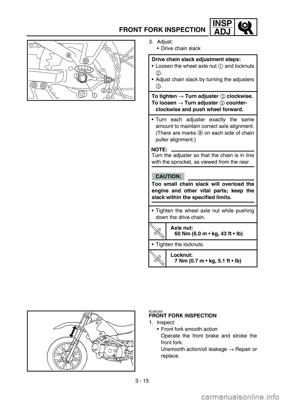
Drive chain slack adjustment steps:
Loosen the wheel axle nut 1 and locknuts
2.
Adjust chain slack by turning the adjusters
3.
To tighten
→ Turn adjuster
3 clockwise.
To loosen
→ Turn adjuster
3 counter-
clockwise and push wheel forward.
Turn each adjuster exactly the same
amount to maintain correct axle alignment.
(There are marks a on each side of chain
puller alignment.)
NOTE:
Turn the adjuster so that the chain is in line
with the sprocket, as viewed from the rear.
CAUTION:
Too small chain slack will overload the
engine and other vital parts; keep the
slack within the specified limits.
Tighten the wheel axle nut while pushing
down the drive chain.
T R..
Axle nut:
60 Nm (6.0 m kg, 43 ft lb)
Tighten the locknuts.
T R..
Locknut:
7 Nm (0.7 m kg, 5.1 ft lb)
13 a2
EC36C000
FRONT FORK INSPECTION
1. Inspect:
Front fork smooth action
Operate the front brake and stroke the
front fork.
Unsmooth action/oil leakage → Repair or
replace.
Page 162 of 390
3 - 16
INSP
ADJREAR SHOCK ABSORBER INSPECTION/
REAR SHOCK ABSORBER SPRING PRELOAD ADJUSTMENT
EC36K000
REAR SHOCK ABSORBER INSPECTION
1. Inspect:
Swingarm smooth action
Abnormal noise/unsmooth action →
Grease the pivoting points or repair the
pivoting points.
Damage/oil leakage → Replace.
REAR SHOCK ABSORBER SPRING
PRELOAD ADJUSTMENT
1. Elevate the rear wheel by placing the suit-
able stand under the engine.
2. Remove:
Rear shock absorber
Refer to “SWINGARM” section in the
CHAPTER 5.
3. Remove:
Spring guide 1
NOTE:
While compressing the spring, remove the
spring guide.
4. To stiffen the spring preload, install the cir-
clip 1 into the groove a. To soften the
spring preload, install the circlip into the
groove b.
NOTE:
Do not spread the circlip too much.
Standard installation position:
Groove b
5. Install:
Spring guide 1
NOTE:
While compressing the spring, install the
spring guide.
Page 216 of 390

4 - 11
ENGCYLINDER HEAD
4. Remove:
Cylinder head
NOTE:
Loosen the bolts and nuts in their proper
loosening sequence.
Start by loosening each bolt and nut 1/2 turn
until all are loose.
ASSEMBLY AND INSTALLATION
1. Install:
Cylinder head
2. Tighten:
Nuts
Bolts
NOTE:
Apply the engine oil on the contact surfaces
of the nuts, bolts and copper washers.
Follow the numerical order shown in the illus-
tration. Tighten the bolts and nuts in two
stages.
T R..22 Nm (2.2 m · kg, 16 ft · lb)
T R..10 Nm (1.0 m · kg, 7.2 ft · lb)
3. Install:
Camshaft sprocket 1
Installation steps:
Turn the crankshaft counterclockwise until
the “I” mark a on the rotor is aligned with
the stationary pointer b on the crankcase
cover.
Align the “I” mark c on the camshaft
sprocket with the stationary pointer d on
the cylinder head.
Fit the timing chain 2 onto camshaft
sprocket and install the camshaft sprocket
on the camshaft.
NOTE:
When installing the camshaft sprocket, keep
the timing chain as tense as possible on the
exhaust side.
Page 222 of 390
4 - 14
ENGCAMSHAFT AND ROCKER ARMS
REMOVAL POINTS
Rocker arm shaft
1. Remove:
Rocker arm shafts
NOTE:
Use a slide hammer bolt 1 and weight 2 to
slide out the rocker arm shafts.
Slide hammer set:
YU-1083-A
Slide hammer bolt:
90890-01085
Weight:
90890-01084
INSPECTION
Camshaft
1. Measure:
Cam lobes length a and b
Out of specification → Replace.
Cam lobes length limit:
Intake:
a 25.398 mm (0.9999 in)
b 21.004 mm (0.8269 in)
Exhaust:
a 25.256 mm (0.9943 in)
b 21.017 mm (0.8274 in)
ASSEMBLY AND INSTALLATION
1. Apply:
Molybdenum disulfide oil
(onto the camshaft cam lobe)
Engine oil
(onto the camshaft bearing)
2. Install:
Camshaft 1
Page 244 of 390
4 - 25
ENGCYLINDER AND PISTON
Piston pin
1. Inspect:
Piston pin
Blue discoloration/grooves →
Replace, then inspect the lubrication sys-
tem.
2. Measure:
Piston pin outside diameter
Piston pin bore inside diameter
ASSEMBLY AND INSTALLATION
Piston
1. Install:
Piston rings
(onto the piston)
NOTE:
Be sure to install the piston rings so that the
manufacturer’s marks or numbers are
located on the upper side of the rings.
Lubricate the piston and piston rings liberally
with engine oil. Measurement steps:
Measure the piston pin outside diameter
a.
If out of specification, replace the piston
pin.
Outside diameter (piston pin):
12.996 ~ 13.000 mm
(0.5117 ~ 0.5118 in)
:12.976 mm (0.5109 in)
Measure the piston inside diameter b.
If out of specification, replace the piston.
Inside diameter (piston):
13.002 ~ 13.013 mm
(0.5119 ~ 0.5123 in)
: 13.045 mm (0.5136 in)