Page 144 of 390

3 - 7
INSP
ADJ
ENGINE OIL REPLACEMENT
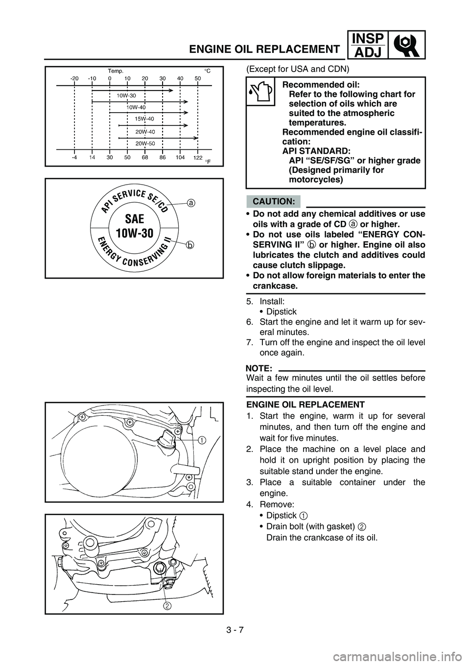
(Except for USA and CDN)
CAUTION:
Do not add any chemical additives or use
oils with a grade of CD
a or higher.
Do not use oils labeled “ENERGY CON-
SERVING II”
b or higher. Engine oil also
lubricates the clutch and additives could
cause clutch slippage.
Do not allow foreign materials to enter the
crankcase.
5. Install:
Dipstick
6. Start the engine and let it warm up for sev-
eral minutes.
7. Turn off the engine and inspect the oil level
once again.
NOTE:
Wait a few minutes until the oil settles before
inspecting the oil level.
Recommended oil:
Refer to the following chart for
selection of oils which are
suited to the atmospheric
temperatures.
Recommended engine oil classifi-
cation:
API STANDARD:
API “SE/SF/SG” or higher grade
(Designed primarily for
motorcycles)
a
b
ENGINE OIL REPLACEMENT
1. Start the engine, warm it up for several
minutes, and then turn off the engine and
wait for five minutes.
2. Place the machine on a level place and
hold it on upright position by placing the
suitable stand under the engine.
3. Place a suitable container under the
engine.
4. Remove:
Dipstick 1
Drain bolt (with gasket) 2
Drain the crankcase of its oil.
Page 248 of 390
4 - 27
ENGCLUTCH
CLUTCH
CRANKCASE COVER (LEFT AND RIGHT)
Extent of removal:
1 Crankcase cover (left) removal
2 Crankcase cover (right) removal
Extent of removal Order Part name Q’ty Remarks
CRANKCASE COVER (LEFT
AND RIGHT) REMOVAL
Preparation for removal Drain the engine oil. Refer to “ENGINE OIL REPLACEMENT”
section in the CHAPTER 3.
1 Shift pedal 1
2 Drive sprocket cover 1
3 Crankcase cover (left) 1
4 Gasket 1
5 Dowel pin 2
6 Clutch adjusting screw 1
7 Kick crank 1
8 Crankcase cover (right) 1
9 Gasket 1
10 Dowel pin 2
2
1
Page 250 of 390
4 - 28
ENGCLUTCH
CLUTCH
Extent of removal:
1 Friction plate and clutch plate removal
2 Clutch housing removal
3 Primary clutch removal
Extent of removal Order Part name Q’ty Remarks
CLUTCH REMOVAL
1 Bolt/clutch spring 4/4
2 Pressure plate 1
3 Washer 1
4 Push rod #1 1
5 Friction plate 5
6 Clutch plate 4
7 Push rod #2 1
8 Clutch boss nut 1
Use special tool.
Refer to “REMOVAL POINTS”. 9 Lock washer 1
10 Clutch boss 1
11 Washer 1
12 Clutch housing 1
2
1
3
Page 252 of 390
4 - 29
ENGCLUTCH
Extent of removal Order Part name Q’ty Remarks
13 Spacer 1
14 Spacer 1
15 Primary clutch nut 1 Use special tool.
Refer to “REMOVAL POINTS”.
16 Washer 1
17 Spacer 1
18 Primary clutch housing 1
19 Primary clutch boss 1
20 Clutch carrier 1
21 One-way clutch assembly 1
22 Washer 1
3
2
Page 254 of 390
4 - 30
ENGCLUTCH
REMOVAL POINTS
Clutch boss
1. Remove:
Clutch boss nut 1
Lock washer 2
Clutch boss
NOTE:
Straighten the lock washer tab and use the
clutch holding tool 3 to hold the clutch boss.
ÈFor USA and CDN
ÉExcept for USA and CDN
Clutch holding tool:
YM-91042/90890-04086ÈÉ
Primary clutch
1. Remove:
Primary clutch nut 1
NOTE:
Loosen the nut while holding the magneto
rotor with the sheave holder 2.
INSPECTION
EC484500
Friction plate
1. Measure:
Friction plate thickness
Out of specification → Replace friction
plate as a set.
Measure at all four points.
Sheave holder:
YS-1880-A/90890-01701
Friction plate thickness:
Standard Limit
2.7 ~ 2.9 mm
(0.106 ~ 0.114 in)2.6 mm
(0.102 in)
Page 256 of 390
4 - 31
ENGCLUTCH
EC484600
Clutch plate
1. Measure:
Clutch plate warpage
Out of specification → Replace clutch
plate as a set.
Use a surface plate 1 and thickness
gauge 2.
EC484400
Clutch spring
1. Measure:
Clutch spring free length a
Out of specification → Replace springs
as a set.
Push rod
1. Measure:
Push rod #2 bend
Out of specification → Replace.
Warp limit:
0.2 mm (0.008 in)
Clutch spring free length
Standard Limit
26.2 mm (1.03 in) 24.2 mm (0.95 in)
Bending limit:
0.5 mm (0.02 in)
Primary clutch
1. Measure:
Primary clutch housing inside diameter
Out of specification → Replace.
Primary clutch housing inside
diameter:
105 mm (4.13 in)
: 106 mm (4.17 in)
2. Measure:
Clutch shoe groove depth a
Out of specification → Replace.
Clutch shoe groove depth:
1.0 ~ 1.3 mm (0.039 ~ 0.051 in)
: 0.1 mm (0.004 in)
Page 258 of 390
4 - 32
ENGCLUTCH
ASSEMBLY AND INSTALLATION
Primary clutch
1. Install:
Washer 1
Nut (primary clutch) 2
NOTE:
Tighten the nut while holding the magneto
rotor with the sheave holder 3.
Clutch
1. Install:
Lock washer 1
Nut (clutch boss) 2
NOTE:
Use the clutch holding tool 3 to hold the clutch
boss.
ÈFor USA and CDN
ÉExcept for USA and CDN
2. Bend:
Lock washer tab
Sheave holder:
YS-1880-A/90890-01701
Clutch holding tool:
YM-91042/90890-04086
T R..50 Nm (5.0 m · kg, 36 ft · lb)
New
T R..70 Nm (7.0 m · kg, 50 ft · lb)
ÈÉ
Clutch release adjustment
1. Adjust:
Clutch release
Adjustment steps:
Loosen the locknut 1.
Turn in the adjuster 2 until it is lightly
seated.
Turn out by 1/8 turn.
Tighten the locknut.
T R..
Locknut:
8 Nm (0.8 m kg, 5.8 ft lb)
Page 260 of 390
4 - 33
ENGKICK AXLE
KICK AXLE
Extent of removal:
1 Kick axle removal
2 Kick axle disassembly
Extent of removal Order Part name Q’ty Remarks
KICK AXLE REMOVAL AND
DISASSEMBLY
Preparation for removal Crankcase cover (right) Refer to “CLUTCH” section.
1 Kick axle assembly 1
2 Circlip 2
3 Spring cover 1
4 Torsion spring 1
5 Spring guide 1
6 Circlip 1
7 Ratchet wheel 1
8Clip 1
9 Circlip 1
10 Washer/wave washer 1/1
11 Kick gear 1
12 Kick axle 1
2
1