Page 290 of 610
4 - 16
ENGCYLINDER HEAD
Warpage limit:
0.03 mm (0.0012 in)
�If the warpage is out of specification,
resurface the cylinder head.
�Place #400 ~ 600 grit wet sandpaper on
the surface plate, and re-surface the head
using a figure-eight sanding pattern.
NOTE:
Rotate the cylinder head several times to
avoid removing too much material from one
side.
ASSEMBLY AND INSTALLATION
Cylinder head
1. Install:
�Dowel pin 1
�Gasket 2 New
2. Install:
�Cylinder head
�Copper washer
�Bolt (cylinder head)
NOTE:
�Apply Quick gasket® (YAMAHA Bond
No.1215) on end of the cylinder head bolts
(M6), as shown.
�Apply the engine oil on the contact surfaces of
the bolts (cylinder head) and copper washers.
�Follow the numerical order shown in the illus-
tration. Tighten the bolts in two stages.
Quick gasket®:
ACC-QUICK-GS-KT
YAMAHA Bond No.1215:
90890-85505
T R..M8 22 Nm (2.2 m · kg, 16 ft · lb)
M6 10 Nm (1.0 m · kg, 7.2 ft · lb)
Page 352 of 610
4 - 47
ENGCLUTCH AND PRIMARY DRIVEN GEAR
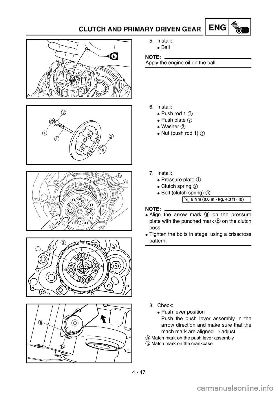
5. Install:
�Ball
NOTE:
Apply the engine oil on the ball.
6. Install:
�Push rod 1 1
�Push plate 2
�Washer 3
�Nut (push rod 1) 4
7. Install:
�Pressure plate 1
�Clutch spring 2
�Bolt (clutch spring) 3
NOTE:
�Align the arrow mark a on the pressure
plate with the punched mark b on the clutch
boss.
�Tighten the bolts in stage, using a crisscross
pattern.
T R..6 Nm (0.6 m · kg, 4.3 ft · lb)
8. Check:
�Push lever position
Push the push lever assembly in the
arrow direction and make sure that the
mach mark are aligned → adjust.
aMatch mark on the push lever assembly
bMatch mark on the crankcase
Page 354 of 610

�Right crankcase cover
�Negative battery lead
(TT-R125E/TT-R125LWE)")
4 - 48
ENGCLUTCH AND PRIMARY DRIVEN GEAR
9. Adjust:
�Push lever position
10. Install:
�Dowel pins
�Gasket (right crankcase cover)
�Right crankcase cover
�Negative battery lead
(TT-R125E/TT-R125LWE) 1
�Lead holder
(TT-R125E/TT-R125LWE) 2
�Bolts (right crankcase cover)
NOTE:
�Apply Quick gasket® (YAMAHA Bond
No.1215) to end of the right crankcase cover
bolts, as shown.
�Tighten the bolts in stages, using a criss-
cross pattern. Adjustment steps:
�Loosen the locknut 1.
�Turn the push rod 1 2 clockwise or coun-
terclockwise to match alignment marks.
�Hold the push rod 1 to prevent it from
moving and tighten the locknut to specifi-
cation.
�Tighten the locknut 1.
T R..
Locknut:
8 Nm (0.8 m • kg, 5.8 ft • lb)
Quick gasket®:
ACC-QUICK-GS-KT
YAMAHA Bond No.1215:
90890-85505
New
T R..10 Nm (1.0 m · kg, 7.2 ft · lb)
11. Install:
�Kickstarter crank 1
�Nut (kickstarter crank) 2
NOTE:
Install the kickstarter crank so that there is 5 ~
10 mm (0.2 ~ 0.4 in) a between the kickstarter
crank and the right crankcase cover.
T R..50 Nm (5.0 m · kg, 36 ft · lb)
Page 378 of 610
4 - 60
ENG
2. Install:
�Woodruff key 1
�Rotor 2
NOTE:
�Clean the tapered portions of the crankshaft
and rotor.
�When installing the woodruff key, make sure
that its flat surface a is in parallel with the
crankshaft center line b.
�When installing the rotor, align the keyway of
the rotor with the woodruff key.
3. Install:
�Plain washer 1
�Nut (rotor) 2
Use the sheave holder 3.
Sheave holder:
YS-1880-A/90890-01701
T R..80 Nm (8.0 m · kg, 58 ft · lb)
4. Install:
�Dowel pin
�Gasket
�Left crankcase cover
�Bolt (left crankcase cover)
NOTE:
Tighten the screws in stage, using a crisscross
pattern.
New
T R..10 Nm (1.0 m · kg, 7.2 ft · lb)
5. Connect:
�CDI magneto lead
Refer to “CABLE ROUTING DIAGRAM”
section in the CHAPTER 2.
CDI MAGNETO (TT-R125/TT-R125LW)
Page 412 of 610
4 - 77
ENGCRANKCASE, CRANKSHAFT AND BALANCER
3. Tighten:
�Lead guide 1
�Clutch cable holder 2
�Bolt (crankcase) [45 mm (1.8 in)] 3
�Bolt (crankcase) [55 mm (2.2 in)] 4
�Bolt (crankcase) [30 mm (1.2 in)] 5
NOTE:
�Apply Quick gasket® (YAMAHA Bond
No.1215) on end of the crankcase bolts
[45 mm (1.8 in)] 3, as shown.
�Tighten the crankcase bolts in stage, using a
crisscross pattern.
Quick gasket®:
ACC-QUICK-GS-KT
YAMAHA Bond No.1215:
90890-85505
T R..10 Nm (1.0 m · kg, 7.2 ft · lb)
T R..10 Nm (1.0 m · kg, 7.2 ft · lb)
T R..10 Nm (1.0 m · kg, 7.2 ft · lb)
4. Check:
�Crankshaft and transmission operation
Unsmooth operation → Repair.
5. Install:
�Timing chain 1
�Intake timing chain guide 2
�Bolt (intake timing chain guide)
T R..10 Nm (1.0 m · kg, 7.2 ft · lb)LT
Page 446 of 610
5 - 11
CHASFRONT WHEEL (TT-R125LW/TT-R125LWE)
2. Install:
�Brake disc 1
�Bolt (brake disc) 2
NOTE:
Tighten the bolts in stage, using a crisscross
pattern.
T R..12 Nm (1.2 m · kg, 8.7 ft · lb)LT
3. Install:
�Collar 1
NOTE:
�Apply the lithium soap base grease on the oil
seal lips.
�Install the longer collar on the brake disc 2
side.
4. Install:
�Front wheel
NOTE:
Install the brake disc 1 between the brake
pads 2 correctly.
5. Install:
�Wheel axle 1
6. Install:
�Washer 1
�Axle nut 2
T R..45 Nm (4.5 m · kg, 32 ft · lb)