Page 32 of 92

INSTRUMENT AND CONTROL FUNCTIONS
3-16
1
2
3
4
5
6
7
8
9
To close the storage compartment,
push the lid into the original position.
WARNING
EWA11160
Do not store heavy items in this
compartment.
Rear storage compartment
Two helmets can be stored in the stor-
age compartment under the seats.
(See page 3-13.)
CAUTION:
ECA10080
Keep the following points in mind
when using the storage compart-
ment.
�
Since the storage compartment
accumulates heat when ex-
posed to the sun, do not store
anything susceptible to heat in-
side it.
�
To avoid humidity from spread-
ing through the storage com-
partment, wrap wet articles in a
plastic bag before storing them
in the compartment.
�
Since the storage compartment
may get wet while the scooter isbeing washed, wrap any articles
stored in the compartment in a
plastic bag.
�
Do not keep anything valuable
or breakable in the storage com-
partment.
CAUTION:
ECA11100
Do not leave the rider seat open for
an extended period of time, other-
wise the light may cause the battery
to discharge.
WARNING
EWA11170
Do not exceed the following loading
limits:
�
Front storage compartment A:
2 kg (4 lb)
�
Rear storage compartment: 5 kg
(11 lb)
�
Maximum load for the vehicle:
194 kg (428 lb)
1. Storage compartment opening lever
2. Lid
2
1
1. Rider seat
1
Page 33 of 92

INSTRUMENT AND CONTROL FUNCTIONS
3-17
2
34
5
6
7
8
9
EAU15301
Sidestand
The sidestand is located on the left side
of the frame. Raise the sidestand or
lower it with your foot while holding the
vehicle upright.
NOTE:
The built-in sidestand switch is part of
the ignition circuit cut-off system, which
cuts the ignition in certain situations.
(See further down for an explanation of
the ignition circuit cut-off system.)
WARNING
EWA10240
The vehicle must not be ridden with
the sidestand down, or if the side-
stand cannot be properly moved up
(or does not stay up), otherwise the
sidestand could contact the ground
and distract the operator, resulting
in a possible loss of control.
Yamaha’s ignition circuit cut-off
system has been designed to assist
the operator in fulfilling the respon-
sibility of raising the sidestand be-
fore starting off. Therefore, check
this system regularly as described
below and have a Yamaha dealer re-pair it if it does not function proper-
ly.
EAU15371
Ignition circuit cut-off system
The ignition circuit cut-off system (com-
prising the sidestand switch and brake
light switches) has the following func-
tions.
�
It prevents starting when the side-
stand is up, but neither brake is ap-
plied.
�
It prevents starting when either
brake is applied, but the sidestand
is still down.
�
It cuts the running engine when the
sidestand is moved down.
Periodically check the operation of the
ignition circuit cut-off system according
to the following procedure.
WARNING
EWA10250
If a malfunction is noted, have a
Yamaha dealer check the system be-
fore riding.
Page 37 of 92
PRE-OPERATION CHECKS
4-3
2
3
45
6
7
8
9
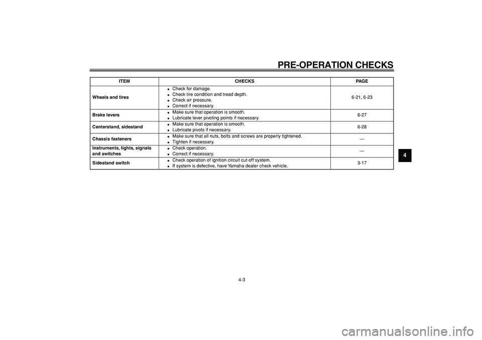
Wheels and tires
�
Check for damage.
�
Check tire condition and tread depth.
�
Check air pressure.
�
Correct if necessary.6-21, 6-23
Brake levers
�
Make sure that operation is smooth.
�
Lubricate lever pivoting points if necessary.6-27
Centerstand, sidestand
�
Make sure that operation is smooth.
�
Lubricate pivots if necessary.6-28
Chassis fasteners
�
Make sure that all nuts, bolts and screws are properly tightened.
�
Tighten if necessary.—
Instruments, lights, signals
and switches
�
Check operation.
�
Correct if necessary.—
Sidestand switch
�
Check operation of ignition circuit cut-off system.
�
If system is defective, have Yamaha dealer check vehicle.3-17
ITEM CHECKS PAGE
Page 40 of 92
OPERATION AND IMPORTANT RIDING POINTS
5-3
1
2
3
4
5
6
7
8
9Rear
WARNING
EWA10300
�
Avoid braking hard or suddenly
(especially when leaning over to
one side), otherwise the scooter
may skid or overturn.
�
Railroad crossings, streetcar
rails, iron plates on road con-
struction sites, and manhole
covers become extremely slip-
pery when wet. Therefore, slow
down when approaching such
areas and cross them with cau-
tion.
�
Keep in mind that braking on a
wet road is much more difficult.
�
Ride slowly down a hill, as brak-
ing downhill can be very diffi-
cult.
EAU16820
Tips for reducing fuel
consumption
Fuel consumption depends largely on
your riding style. Consider the following
tips to reduce fuel consumption:
�
Avoid high engine speeds during
acceleration.
�
Avoid high engine speeds with no
load on the engine.
�
Turn the engine off instead of let-
ting it idle for an extended length of
time (e.g., in traffic jams, at traffic
lights or at railroad crossings).
Page 46 of 92
PERIODIC MAINTENANCE AND MINOR REPAIR
6-5
1
2
3
4
5
6
7
8
9
EAU34490
NOTE:
�
The air filters and V-belt filter need more frequent service if you are riding in unusually wet or dusty areas.
�
Hydraulic brake service
�
Regularly check and, if necessary, correct the brake fluid level.
�
Every two years replace the internal components of the brake master cylinders and calipers, and change the brake
fluid.
�
Replace the brake hoses every four years and if cracked or damaged.
26
Moving parts and cables
�
Lubricate.
√√√√ √
27
*
Throttle grip housing
and cable
�
Check operation and free play.
�
Adjust the throttle cable free play if necessary.
�
Lubricate the throttle grip housing and cable.
√√√√ √
28
*
Lights, signals and
switches
�
Check operation.
�
Adjust headlight beam.
√√√√√ √
NO. ITEM CHECK OR MAINTENANCE JOBODOMETER READING (
×
1000 km)
ANNUAL
CHECK
1 10203040
Page 49 of 92
PERIODIC MAINTENANCE AND MINOR REPAIR
6-8
2
3
4
5
67
8
9
2. Install the screw access cover by
placing it in its original position.
3. Install the grab bar by installing the
collars and grab bar bolts.
4. Install the passenger seat.
5. Install cowlings A and B.
Cowling E
To remove the cowling
1. Pull up the left floorboard mats as
shown.2. Remove the cowling screws.
3. Pull the cowling down slightly, and
then pull it outward as shown.To install the cowling
1. Insert the tabs on the cowling into
the slots as shown, and then install
the screws.
2. Place the left floorboard mats in
the original position.
Tightening torque:
Grab bar bolt:
23 Nm (2.3 m·kgf, 16.6 ft·lbf)
1. Left floorboard mat
1. Screw
1
1
1. Cowling E
1. Tab
1
1
1
Page 51 of 92

PERIODIC MAINTENANCE AND MINOR REPAIR
6-10
2
3
4
5
67
8
9
EAU34171
Checking the spark plug
The spark plug is an important engine
component, which is easy to check.
Since heat and deposits will cause any
spark plug to slowly erode, the spark
plug should be removed and checked
in accordance with the periodic mainte-
nance and lubrication chart. In addition,
the condition of the spark plug can re-
veal the condition of the engine.
To remove the spark plug
1. Open the rider seat. (See
page 3-13.)
2. Pull up the storage compartment
mat, and then remove the spark
plug cover by removing the
screws.3. Remove the spark plug cap.
4. Remove the spark plug as shown,
with the spark plug wrench includ-
ed in the owner’s tool kit.
To check the spark plug
1. Check that the porcelain insulator
around the center electrode of the
spark plug is a medium-to-light tan
(the ideal color when the vehicle is
ridden normally).
NOTE:
If the spark plug shows a distinctly dif-
ferent color, the engine could be defec-
tive. Do not attempt to diagnose such
problems yourself. Instead, have a
Yamaha dealer check the vehicle.
2. Check the spark plug for electrode
erosion and excessive carbon or
other deposits, and replace it if
necessary.
1. Storage compartment mat
2. Spark plug cover
3. Screw
1. Spark plug cap
1
2
3
1
1. Spark plug wrench
1
Page 53 of 92

PERIODIC MAINTENANCE AND MINOR REPAIR
6-12
2
3
4
5
67
8
9
EAU34181
Engine oil and oil filter
element
The engine oil level should be checked
before each ride. In addition, the oil
must be changed and the oil filter ele-
ment replaced at the intervals specified
in the periodic maintenance and lubri-
cation chart and when the oil change in-
dicator comes on.
To check the engine oil level
1. Place the vehicle on the center-
stand.
NOTE:
Make sure that the vehicle is positioned
straight up when checking the oil level.
A slight tilt to the side can result in a
false reading.
2. Start the engine, warm it up for
several minutes, and then turn it
off.
3. Wait a few minutes until the oil set-
tles, remove the oil filler cap, wipe
the dipstick clean, insert it back
into the oil filler hole (without
screwing it in), and then remove it
again to check the oil level.
NOTE:
The engine oil should be between the
minimum and maximum level marks.
4. If the engine oil is below the mini-
mum level mark, add sufficient oil
of the recommended type to raise
it to the correct level.
5. Insert the dipstick into the oil filler
hole, and then tighten the oil filler
cap.
To change the engine oil (with or
without oil filter element replace-
ment)
1. Start the engine, warm it up for
several minutes, and then turn it
off.
2. Place an oil pan under the engine
to collect the used oil.
3. Remove the engine oil filler cap
and the engine oil drain bolt to
drain the oil from the crankcase.
4. Check the washer for damage and
replace it if necessary.
1. Engine oil filler cap
2. Dipstick
3. Maximum level mark
4. Minimum level mark
1
3
4
1
2
1. Engine oil drain bolt
1