Page 35 of 100

INSTRUMENT AND CONTROL FUNCTIONS
3-21
3
EAU39450
Fuel tank breather/overflow
hose Before operating the motorcycle:�
Check the fuel tank breather/over-
flow hose connection.
�
Check the fuel tank breather/over-
flow hose for cracks or damage,
and replace it if damaged.
�
Make sure that the end of the fuel
tank breather/overflow hose is not
blocked, and clean it if necessary.
EAU13441
Catalytic converter This vehicle is equipped with catalytic
converters in the exhaust system.
WARNING
EWA10860
The exhaust system is hot after op-
eration. Make sure that the exhaust
system has cooled down before do-ing any maintenance work.CAUTION:
ECA10700
The following precautions must be
observed to prevent a fire hazard or
other damages.�
Use only unleaded gasoline.
The use of leaded gasoline will
cause unrepairable damage to
the catalytic converter.
�
Never park the vehicle near pos-
sible fire hazards such as grass
or other materials that easily
burn.
�
Do not allow the engine to idletoo long.
EAU39491
Seats Passenger seat
To remove the passenger seat1. Insert the key into the seat lock,
and then turn it counterclockwise.
2. Lift the front of the passenger seat
and pull it forward.
To install the passenger seat1. Insert the projections on the rear of
the passenger seat into the seat
holders as shown, and then push
the front of the seat down to lock it
in place.
1. Fuel tank breather/overflow hose
1. Passenger seat lock
2. Unlock.
U2D2EAE0.book Page 21 Monday, June 26, 2006 2:55 PM
Page 36 of 100
INSTRUMENT AND CONTROL FUNCTIONS
3-22
3
2. Remove the key.
Rider seat
To remove the rider seat
1. Remove the passenger seat.
2. Push the rider seat lock lever, lo-
cated under the back of the rider
seat, to the left as shown, and then
pull the seat off.To install the rider seat
1. Insert the projection on the front of
the rider seat into the seat holder
as shown, and then push the rear
of the seat down to lock it in place.2. Install the passenger seat.
NOTE:�
Make sure that the seats are prop-
erly secured before riding.
�
The rider seat height can be ad-
justed to change the riding posi-tion. (See page 3-23.)
1. Projection
2. Seat holder
1. Rider seat lock lever
2. Rider seat
1. Projection
2. Seat holder
U2D2EAE0.book Page 22 Monday, June 26, 2006 2:55 PM
Page 39 of 100

INSTRUMENT AND CONTROL FUNCTIONS
3-25
3
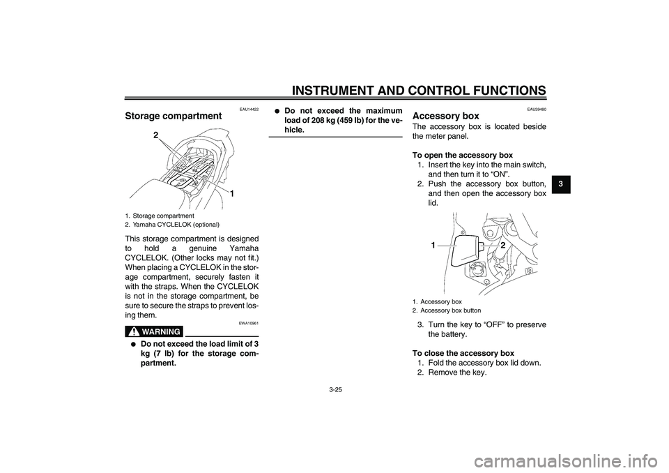
EAU14422
Storage compartment This storage compartment is designed
to hold a genuine Yamaha
CYCLELOK. (Other locks may not fit.)
When placing a CYCLELOK in the stor-
age compartment, securely fasten it
with the straps. When the CYCLELOK
is not in the storage compartment, be
sure to secure the straps to prevent los-
ing them.
WARNING
EWA10961
�
Do not exceed the load limit of 3
kg (7 lb) for the storage com-
partment.
�
Do not exceed the maximum
load of 208 kg (459 lb) for the ve-hicle.
EAU39480
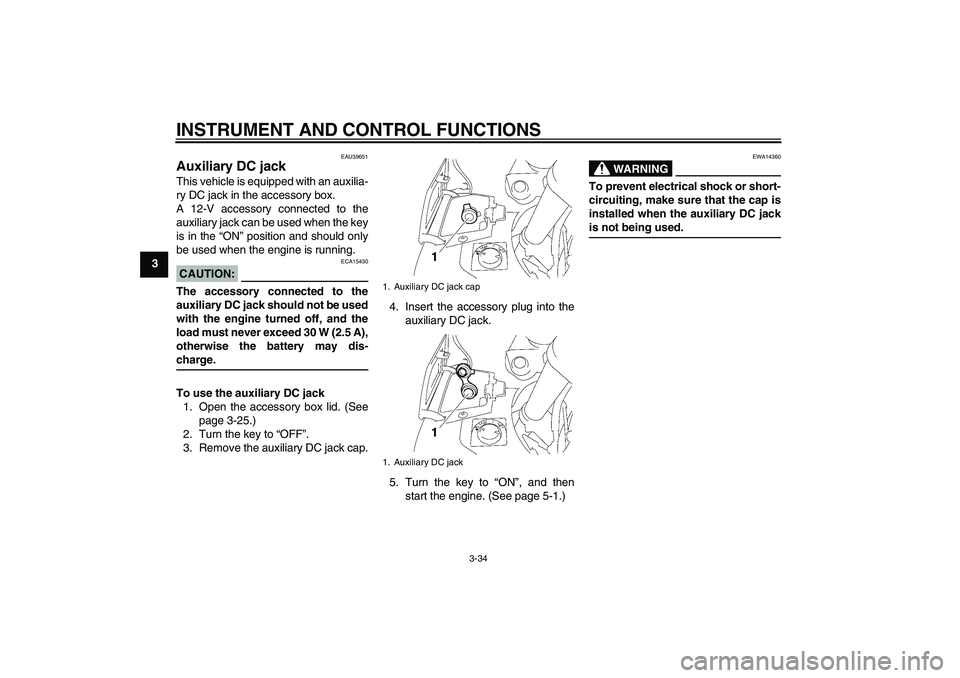
Accessory box The accessory box is located beside
the meter panel.
To open the accessory box
1. Insert the key into the main switch,
and then turn it to “ON”.
2. Push the accessory box button,
and then open the accessory box
lid.
3. Turn the key to “OFF” to preserve
the battery.
To close the accessory box
1. Fold the accessory box lid down.
2. Remove the key.
1. Storage compartment
2. Yamaha CYCLELOK (optional)
1. Accessory box
2. Accessory box button
U2D2EAE0.book Page 25 Monday, June 26, 2006 2:55 PM
Page 47 of 100

INSTRUMENT AND CONTROL FUNCTIONS
3-33
3
With the engine turned off:
1. Move the sidestand down.
2. Make sure that the engine stop switch is turned on.
3. Turn the key on.
4. Shift the transmission into the neutral position.
5. Keep the front or rear brake applied.
6. Push the start switch.
Does the engine start?
With the engine still running:
7. Move the sidestand up.
8. Keep the front or rear brake applied.
9. Shift the transmission into gear.
10. Move the sidestand down.
Does the engine stall?
After the engine has stalled:
11. Move the sidestand up.
12. Release the brake.
13. Push the start switch.
Does the engine start?
The system is OK. The vehicle can be ridden.
This check is most reliable if performed with
a warmed-up engine.The neutral, the brake switch or the YCC-S
system may be defective.
The vehicle should not be ridden until
checked by a Yamaha dealer.
The sidestand switch may be defective.
The vehicle should not be ridden until
checked by a Yamaha dealer.
A brake switch may be defective.
The vehicle should not be ridden until
checked by a Yamaha dealer.
NO YES YES NO YES NONOTE:
U2D2EAE0.book Page 33 Monday, June 26, 2006 2:55 PM
Page 48 of 100

INSTRUMENT AND CONTROL FUNCTIONS
3-34
3
EAU39651
Auxiliary DC jack This vehicle is equipped with an auxilia-
ry DC jack in the accessory box.
A 12-V accessory connected to the
auxiliary jack can be used when the key
is in the “ON” position and should only
be used when the engine is running.CAUTION:
ECA15430
The accessory connected to the
auxiliary DC jack should not be used
with the engine turned off, and the
load must never exceed 30 W (2.5 A),
otherwise the battery may dis-charge.
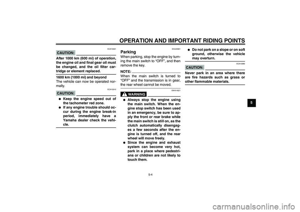
To use the auxiliary DC jack
1. Open the accessory box lid. (See
page 3-25.)
2. Turn the key to “OFF”.
3. Remove the auxiliary DC jack cap.4. Insert the accessory plug into the
auxiliary DC jack.
5. Turn the key to “ON”, and then
start the engine. (See page 5-1.)
WARNING
EWA14360
To prevent electrical shock or short-
circuiting, make sure that the cap is
installed when the auxiliary DC jackis not being used.
1. Auxiliary DC jack cap
1. Auxiliary DC jack
U2D2EAE0.book Page 34 Monday, June 26, 2006 2:55 PM
Page 52 of 100

OPERATION AND IMPORTANT RIDING POINTS
5-1
5
EAU15950
WARNING
EWA10270
�
Become thoroughly familiar
with all operating controls and
their functions before riding.
Consult a Yamaha dealer re-
garding any control or function
that you do not thoroughly un-
derstand.
�
Never start the engine or oper-
ate it in a closed area for any
length of time. Exhaust fumes
are poisonous, and inhaling
them can cause loss of con-
sciousness and death within a
short time. Always make sure
that there is adequate ventila-
tion.
�
Before starting out, make sure
that the sidestand is up. If the
sidestand is not raised com-
pletely, it could contact the
ground and distract the opera-
tor, resulting in a possible lossof control.
EAU40331
Starting the engine In order for the ignition circuit cut-off
system to enable starting, one of the
following conditions must be met:�
The front or rear brake is applied
with the transmission in the neutral
position whether the sidestand is
up or down.
�
The front or rear brake is applied
with the transmission in gear and
the sidestand is up.WARNING
EWA14540
�
Before starting the engine,
check the function of the igni-
tion circuit cut-off system ac-
cording to the procedure
described on page 3-32.
�
Always apply the front or rear
brake while the main switch is in
the “ON” position and the trans-
mission is in gear, otherwise the
rear wheel will move freely.
�
Never ride with the sidestanddown.
1. Turn the key to “ON” and make
sure that the engine stop switch is
set to “”.
CAUTION:
ECA15510
The following warning lights and in-
dicator light and indicators should
come on for a few seconds, then go
off.�
Oil level warning light
�
Engine trouble/YCC-S indica-
tors and warning light
�
Immobilizer system indicator
light
�
ABS warning light
If a warning or indicator light, or an
indicator does not go off, see page
3-4 for the corresponding circuit
check.
2. Shift the transmission into the neu-
tral position with the front or rear
brake applied.NOTE:When the transmission is in the neutral
position, the neutral indicator light
should be on, otherwise have a
Yamaha dealer check the electrical cir-cuit.
3. Start the engine by pushing the
start switch.
U2D2EAE0.book Page 1 Monday, June 26, 2006 2:55 PM
Page 55 of 100

OPERATION AND IMPORTANT RIDING POINTS
5-4
5
CAUTION:
ECA10331
After 1000 km (600 mi) of operation,
the engine oil and final gear oil must
be changed, and the oil filter car-tridge or element replaced.
1600 km (1000 mi) and beyond
The vehicle can now be operated nor-
mally.CAUTION:
ECA10310
�
Keep the engine speed out of
the tachometer red zone.
�
If any engine trouble should oc-
cur during the engine break-in
period, immediately have a
Yamaha dealer check the vehi-cle.
EAU40581
Parking When parking, stop the engine by turn-
ing the main switch to “OFF”, and then
remove the key.NOTE:When the main switch is turned to
“OFF” and the transmission is in gear,the rear wheel cannot be moved.
WARNING
EWA14521
�
Always stop the engine using
the main switch. When the en-
gine stop switch has been used
in an emergency, be sure to ap-
ply the front or rear brake while
the main switch is still on, as the
clutch automatically disengag-
es a few seconds after the en-
gine is turned off, and the rear
wheel will move freely.
�
Since the engine and exhaust
system can become very hot,
park in a place where pedestri-
ans or children are not likely to
touch them.
�
Do not park on a slope or on soft
ground, otherwise the vehiclemay overturn.
CAUTION:
ECA10380
Never park in an area where there
are fire hazards such as grass orother flammable materials.
U2D2EAE0.book Page 4 Monday, June 26, 2006 2:55 PM
Page 74 of 100

PERIODIC MAINTENANCE AND MINOR REPAIR
6-19
6indicator groove has almost disap-
peared, have a Yamaha dealer replace
the brake pads as a set.
EAU22500
Rear brake pads
Check each rear brake pad for damage
and measure the lining thickness. If a
brake pad is damaged or if the lining
thickness is less than 0.8 mm (0.03 in),
have a Yamaha dealer replace the
brake pads as a set.
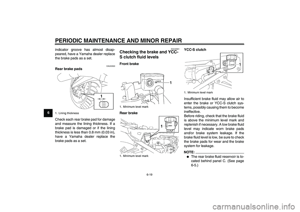
EAU40591
Checking the brake and YCC-
S clutch fluid levels Front brake
Rear brakeYCC-S clutch
Insufficient brake fluid may allow air to
enter the brake or YCC-S clutch sys-
tems, possibly causing them to become
ineffective.
Before riding, check that the brake fluid
is above the minimum level mark and
replenish if necessary. A low brake fluid
level may indicate worn brake pads
and/or brake system leakage. If the
brake fluid level is low, be sure to check
the brake pads for wear and the brake
system for leakage.
NOTE:�
The rear brake fluid reservoir is lo-
cated behind panel C. (See page
6-5.)
1. Lining thickness
1. Minimum level mark
1. Minimum level mark
1. Minimum level mark
U2D2EAE0.book Page 19 Monday, June 26, 2006 2:55 PM