Page 630 of 2000

EM–862AZ-FE ENGINE MECHANICAL – CYLINDER HEAD
EM
22. INSTALL ENGINE MOUNTING INSULATOR RH (See
page EM-41)
23. INSTALL RADIATOR RESERVOIR (See page EM-112)
24. INSTALL GENERATOR ASSEMBLY (See page CH-15)
25. INSTALL FAN AND GENERATOR V BELT (See page
EM-7)
26. INSTALL FRONT SUSPENSION MEMBER
REINFORCEMENT RH (See page EM-7)
27. CONNECT ENGINE WIRE
(a) Connect the ground cable with the bolt.
Torque: 8.4 N*m (86 kgf*cm, 74 in.*lbf)
(b) Connect the camshaft position sensor connector.
(c) Connect the engine coolant temperature sensor
connector.
(d) Connect the engine oil pressure switch connector.
(e) Connect the radio setting condenser connector.
(f) Connect the heater water inlet hose.
28. CONNECT NO. 1 RADIATOR HOSE
(a) Connect the hose to the cylinder head.
29. INSTALL CAMSHAFT TIMING OIL CONTROL VALVE
ASSEMBLY (See page ES-396)
30. INSTALL EXHAUST MANIFOLD CONVERTER SUB-
ASSEMBLY
(a) Install a new gasket onto the cylinder head.
(b) Temporarily tighten the exhaust manifold converter
with the 5 nuts.
(c) Tighten the 5 nuts in the sequence shown in the
illustration.
Torque: 37 N*m (377 kgf*cm, 27 ft.*lbf)
(d) Connect the air-fuel ratio sensor connector.
A098748E01
A114348
A112190E01
A098744E01
Page 631 of 2000
2AZ-FE ENGINE MECHANICAL – CYLINDER HEADEM–87
EM
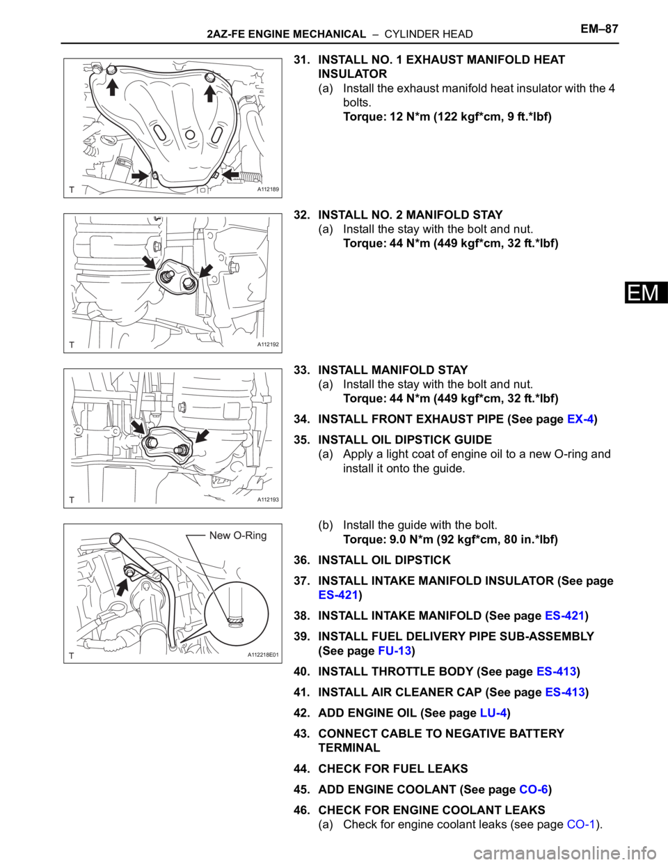
31. INSTALL NO. 1 EXHAUST MANIFOLD HEAT
INSULATOR
(a) Install the exhaust manifold heat insulator with the 4
bolts.
Torque: 12 N*m (122 kgf*cm, 9 ft.*lbf)
32. INSTALL NO. 2 MANIFOLD STAY
(a) Install the stay with the bolt and nut.
Torque: 44 N*m (449 kgf*cm, 32 ft.*lbf)
33. INSTALL MANIFOLD STAY
(a) Install the stay with the bolt and nut.
Torque: 44 N*m (449 kgf*cm, 32 ft.*lbf)
34. INSTALL FRONT EXHAUST PIPE (See page EX-4)
35. INSTALL OIL DIPSTICK GUIDE
(a) Apply a light coat of engine oil to a new O-ring and
install it onto the guide.
(b) Install the guide with the bolt.
Torque: 9.0 N*m (92 kgf*cm, 80 in.*lbf)
36. INSTALL OIL DIPSTICK
37. INSTALL INTAKE MANIFOLD INSULATOR (See page
ES-421)
38. INSTALL INTAKE MANIFOLD (See page ES-421)
39. INSTALL FUEL DELIVERY PIPE SUB-ASSEMBLY
(See page FU-13)
40. INSTALL THROTTLE BODY (See page ES-413)
41. INSTALL AIR CLEANER CAP (See page ES-413)
42. ADD ENGINE OIL (See page LU-4)
43. CONNECT CABLE TO NEGATIVE BATTERY
TERMINAL
44. CHECK FOR FUEL LEAKS
45. ADD ENGINE COOLANT (See page CO-6)
46. CHECK FOR ENGINE COOLANT LEAKS
(a) Check for engine coolant leaks (see page CO-1).
A112189
A112192
A112193
A112218E01
Page 633 of 2000
EM–982AZ-FE ENGINE MECHANICAL – ENGINE ASSEMBLY
EM
REMOVAL
1. DISCHARGE FUEL SYSTEM PRESSURE (See page
FU-9)
2. DISCONNECT CABLE FROM NEGATIVE BATTERY
TERMINAL
CAUTION:
Wait at least 90 seconds after disconnecting the
cable from the negative (-) battery terminal to
prevent airbag and seat belt pretensioner activation.
3. REMOVE HOOD SUB-ASSEMBLY (See page ED-4)
4. REMOVE RADIATOR SUPPORT OPENING COVER
5. REMOVE BATTERY CLAMP SUB-ASSEMBLY
(a) Loosen the bolt and nut, and remove the battery
clamp.
6. REMOVE BATTERY
7. REMOVE BATTERY TRAY
8. REMOVE FRONT WHEEL
9. REMOVE NO. 1 ENGINE UNDER COVER
10. REMOVE NO. 2 ENGINE UNDER COVER
11. REMOVE FRONT FENDER APRON RH
12. REMOVE NO. 1 ENGINE COVER (See page EM-22)
13. DRAIN ENGINE COOLANT (See page CO-6)
14. DRAIN AUTOMATIC TRANSAXLE FLUID
(a) Drain automatic transaxle fluid for U241E (2WD)
(see page AX-146).
(b) Drain automatic transaxle fluid for U140F (4WD)
(see page AX-147).
15. REMOVE RADIATOR ASSEMBLY
(a) Remove the radiator (see page CO-29).
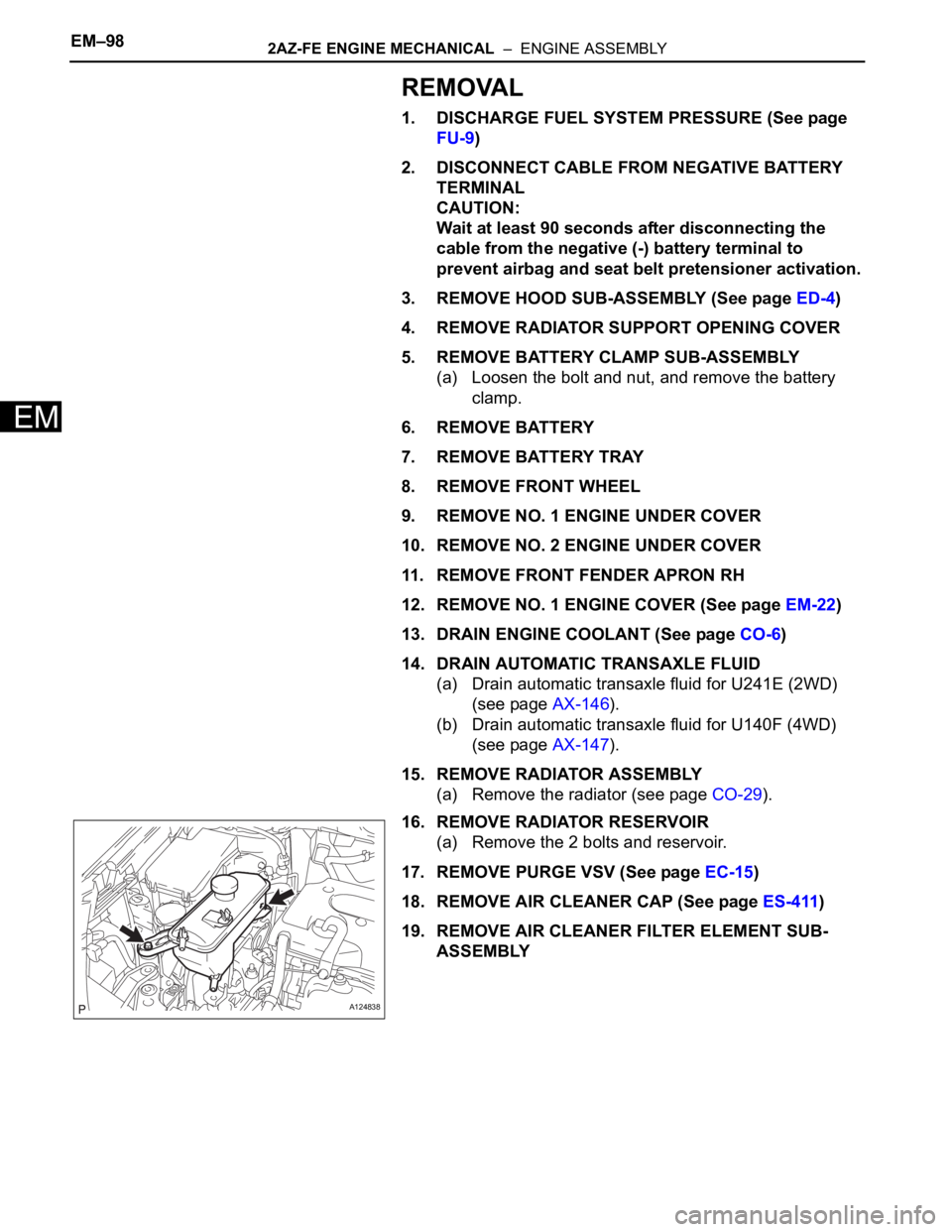
16. REMOVE RADIATOR RESERVOIR
(a) Remove the 2 bolts and reservoir.
17. REMOVE PURGE VSV (See page EC-15)
18. REMOVE AIR CLEANER CAP (See page ES-411)
19. REMOVE AIR CLEANER FILTER ELEMENT SUB-
ASSEMBLY
A124838
Page 648 of 2000
2AZ-FE ENGINE MECHANICAL – ENGINE ASSEMBLYEM–113
EM
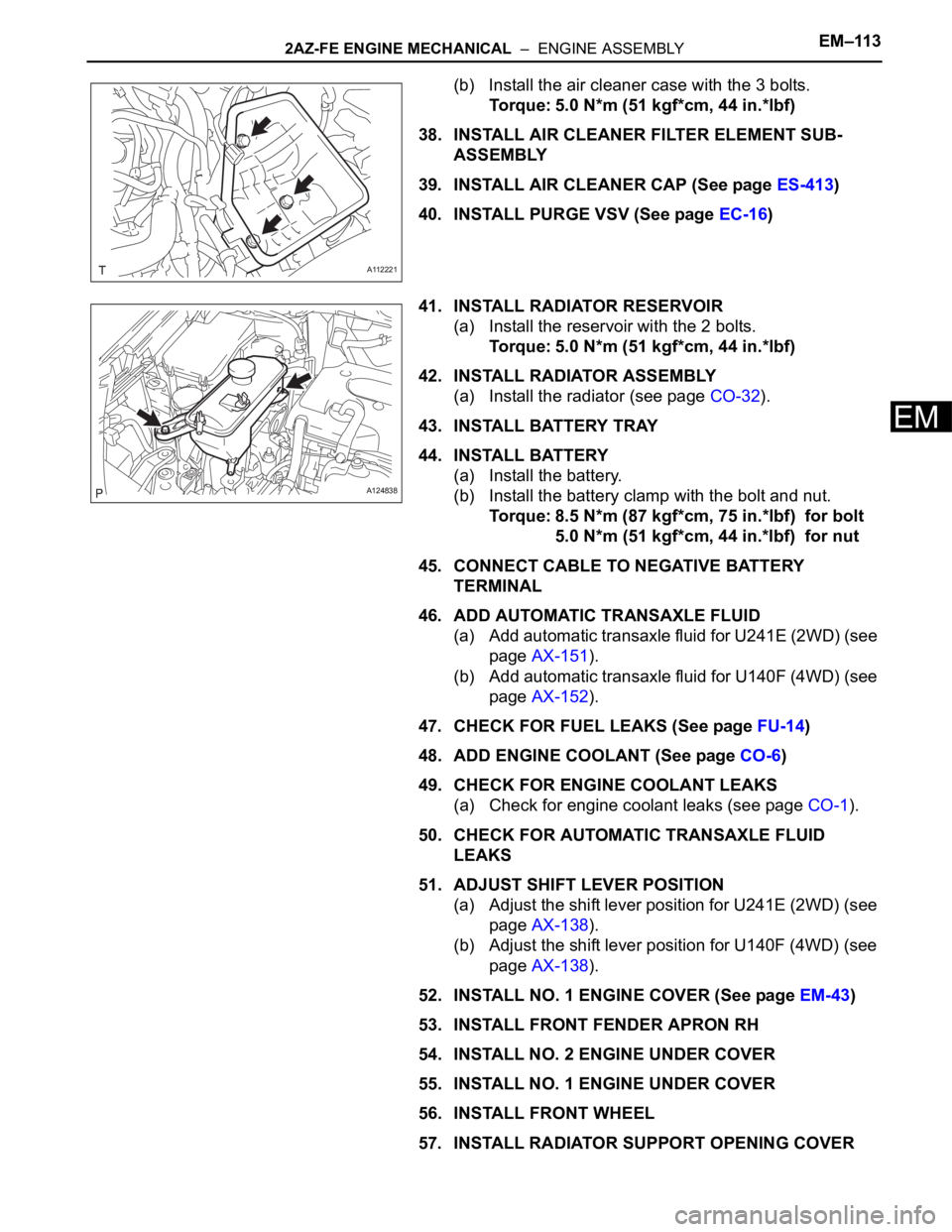
(b) Install the air cleaner case with the 3 bolts.
Torque: 5.0 N*m (51 kgf*cm, 44 in.*lbf)
38. INSTALL AIR CLEANER FILTER ELEMENT SUB-
ASSEMBLY
39. INSTALL AIR CLEANER CAP (See page ES-413)
40. INSTALL PURGE VSV (See page EC-16)
41. INSTALL RADIATOR RESERVOIR
(a) Install the reservoir with the 2 bolts.
Torque: 5.0 N*m (51 kgf*cm, 44 in.*lbf)
42. INSTALL RADIATOR ASSEMBLY
(a) Install the radiator (see page CO-32).
43. INSTALL BATTERY TRAY
44. INSTALL BATTERY
(a) Install the battery.
(b) Install the battery clamp with the bolt and nut.
Torque: 8.5 N*m (87 kgf*cm, 75 in.*lbf) for bolt
5.0 N*m (51 kgf*cm, 44 in.*lbf) for nut
45. CONNECT CABLE TO NEGATIVE BATTERY
TERMINAL
46. ADD AUTOMATIC TRANSAXLE FLUID
(a) Add automatic transaxle fluid for U241E (2WD) (see
page AX-151).
(b) Add automatic transaxle fluid for U140F (4WD) (see
page AX-152).
47. CHECK FOR FUEL LEAKS (See page FU-14)
48. ADD ENGINE COOLANT (See page CO-6)
49. CHECK FOR ENGINE COOLANT LEAKS
(a) Check for engine coolant leaks (see page CO-1).
50. CHECK FOR AUTOMATIC TRANSAXLE FLUID
LEAKS
51. ADJUST SHIFT LEVER POSITION
(a) Adjust the shift lever position for U241E (2WD) (see
page AX-138).
(b) Adjust the shift lever position for U140F (4WD) (see
page AX-138).
52. INSTALL NO. 1 ENGINE COVER (See page EM-43)
53. INSTALL FRONT FENDER APRON RH
54. INSTALL NO. 2 ENGINE UNDER COVER
55. INSTALL NO. 1 ENGINE UNDER COVER
56. INSTALL FRONT WHEEL
57. INSTALL RADIATOR SUPPORT OPENING COVER
A112221
A124838
Page 650 of 2000

2AZ-FE ENGINE MECHANICAL – ENGINE UNITEM–123
EM
DISASSEMBLY
1. REMOVE IDLER PULLEY (See page EM-23)
2. REMOVE OIL DIPSTICK
3. REMOVE OIL DIPSTICK GUIDE (See page EM-57)
4. REMOVE MANIFOLD STAY (See page EM-57)
5. REMOVE NO. 2 MANIFOLD STAY (See page EM-58)
6. REMOVE NO. 1 EXHAUST MANIFOLD HEAT
INSULATOR (See page EM-58)
7. REMOVE EXHAUST MANIFOLD CONVERTER SUB-
ASSEMBLY (See page EM-58)
8. REMOVE WATER INLET (See page CO-15)
9. REMOVE THERMOSTAT
10. REMOVE NO. 1 WATER BY-PASS PIPE
(a) Remove the bolt, 2 nuts, pipe and gasket.
11. REMOVE NO. 3 WATER BY-PASS PIPE
(a) Remove the bolt, 2 nuts, pipe and gasket.
12. REMOVE V-RIBBED BELT TENSIONER ASSEMBLY
(See page EM-26)
13. REMOVE CAMSHAFT TIMING OIL CONTROL VALVE
ASSEMBLY (See page ES-395)
14. REMOVE KNOCK SENSOR (See page ES-420)
15. REMOVE RADIO SETTING CONDENSER (See page
EM-63)
16. REMOVE OIL PRESSURE SWITCH ASSEMBLY (See
page EM-63)
17. REMOVE ENGINE COOLANT TEMPERATURE
SENSOR (See page EM-63)
18. REMOVE CAMSHAFT POSITION SENSOR (See page
EM-64)
19. REMOVE IGNITION COIL ASSEMBLY (See page IG-9)
A112226
A126940
Page 677 of 2000

2GR-FE ENGINE MECHANICAL – ENGINE ASSEMBLYEM–31
EM
INSTALLATION
1. INSTALL ENGINE COOLANT TEMPERATURE
SENSOR
(a) Using a 19 mm deep socket wrench, install the
sensor and a new gasket.
Torque: 20 N*m (204 kgf*cm, 14 ft.*lbf)
2. INSTALL KNOCK SENSOR (See page ES-459)
3. INSTALL ENGINE OIL PRESSURE SWITCH
ASSEMBLY
(a) Clean the threads of the oil pressure switch. Apply
adhesive to 2 or 3 threads of the oil pressure switch.
Adhesive:
Toyota Genuine Adhesive 1344, Three Bond
1344 or Equivalent
(b) Using a 24 mm deep socket wrench, install the oil
pressure switch.
Torque: 21 N*m (214 kgf*cm, 15 ft.*lbf)
4. INSTALL NO. 1 FRONT ENGINE MOUNTING
BRACKET LH
(a) Install the mounting bracket with the 6 bolts.
Torque: 54 N*m (551 kgf*cm, 40 ft.*lbf)
5. INSTALL WATER PUMP PULLEY (See page CO-14)
6. INSTALL NO. 2 IDLER PULLEY SUB-ASSEMBLY
(a) Install the idler pulley and cover plate with the bolt.
Torque: 43 N*m (438 kgf*cm, 32 ft.*lbf)
7. INSTALL NO. 2 TIMING GEAR COVER
(a) Install the gear cover with the 2 bolts.
Torque: 6.0 N*m (61 kgf*cm, 53 in.*lbf)
8. INSTALL V-RIBBED BELT TENSIONER ASSEMBLY
(a) Temporarily install the V-ribbed belt tensioner with
the 5 bolts.
(b) Install the V-ribbed belt tensioner by tightening the
bolt 1 and bolt 2 in the order shown in the
illustration.
Torque: 43 N*m (438 kgf*cm, 32 ft.*lbf)
(c) Tighten the other bolts.
Torque: 43 N*m (438 kgf*cm, 32 ft.*lbf)
Each bolt length is as follows:
A129648
A129647
A129646
A139522
A139138E01
A 70 mm (2.76 in.)
Page 687 of 2000
2GR-FE ENGINE MECHANICAL – ENGINE ASSEMBLYEM–41
EM
62. ADD AUTOMATIC TRANSAXLE FLUID
(a) 2WD:
Add automatic transmission fluid (see page AX-
177).
(b) 4WD:
Add automatic transmission fluid (see page AX-
178).
63. ADD TRANSFER OIL (for 4WD) (See page TF-45)
64. ADD ENGINE OIL (See page LU-6)
65. ADD ENGINE COOLANT (See page CO-8)
66. CHARGE REFRIGERANT (See page AC-172)
67. CHECK FOR LEAKAGE OF REFRIGERANT (See
page AC-173)
68. CHECK FOR ENGINE OIL LEAKS (See page LU-6)
69. CHECK FOR ENGINE COOLANT LEAKS (See page
CO-1)
70. CHECK FOR FUEL LEAKS
71. INSPECT EXHAUST GAS LEAKS
72. INSPECT SHIFT LEVER POSITION
(a) 2WD:
Inspect the shift lever position (see page AX-159).
(b) 4WD:
Inspect the shift lever position (see page AX-158).
73. ADJUST TRANSMISSION CONTROL CABLE
(a) 2WD:
Adjust the shift lever position (see page AX-159).
(b) 4WD:
Adjust the shift lever position (see page AX-159).
74. INSTALL FRONT FLOOR COVER (See page FU-39)
75. INSTALL NO. 2 ENGINE UNDER COVER
(a) Install the under cover with the 2 clips.
76. INSTALL REAR ENGINE UNDER COVER LH
(a) Install the under cover with the 2 clips.
77. INSTALL REAR ENGINE UNDER COVER RH
(a) Install the under cover with the 2 clips.
78. INSTALL NO. 1 ENGINE UNDER COVER
(a) Install the under cover with the 4 bolts and 12 clips.
Page 808 of 2000
FU–182GR-FE FUEL – FUEL INJECTOR
FU
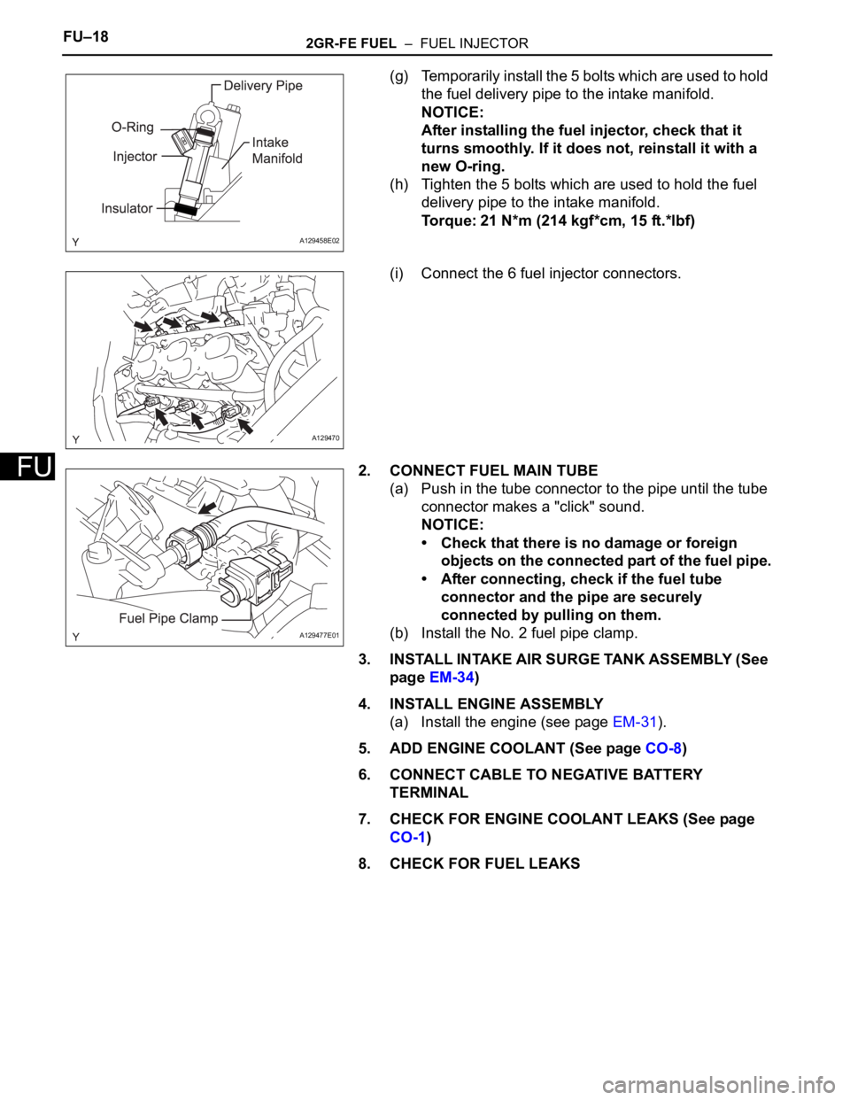
(g) Temporarily install the 5 bolts which are used to hold
the fuel delivery pipe to the intake manifold.
NOTICE:
After installing the fuel injector, check that it
turns smoothly. If it does not, reinstall it with a
new O-ring.
(h) Tighten the 5 bolts which are used to hold the fuel
delivery pipe to the intake manifold.
Torque: 21 N*m (214 kgf*cm, 15 ft.*lbf)
(i) Connect the 6 fuel injector connectors.
2. CONNECT FUEL MAIN TUBE
(a) Push in the tube connector to the pipe until the tube
connector makes a "click" sound.
NOTICE:
• Check that there is no damage or foreign
objects on the connected part of the fuel pipe.
• After connecting, check if the fuel tube
connector and the pipe are securely
connected by pulling on them.
(b) Install the No. 2 fuel pipe clamp.
3. INSTALL INTAKE AIR SURGE TANK ASSEMBLY (See
page EM-34)
4. INSTALL ENGINE ASSEMBLY
(a) Install the engine (see page EM-31).
5. ADD ENGINE COOLANT (See page CO-8)
6. CONNECT CABLE TO NEGATIVE BATTERY
TERMINAL
7. CHECK FOR ENGINE COOLANT LEAKS (See page
CO-1)
8. CHECK FOR FUEL LEAKS
A129458E02
A129470
A129477E01