2006 SUZUKI SX4 Brake light
[x] Cancel search: Brake lightPage 674 of 1556

Downloaded from www.Manualslib.com manuals search engine 5A-26 Automatic Transmission/Transaxle:
Scan Tool Data Definitions:
GEAR POSITION
Current gear position computed by throttle position
coming from ECM and vehicle speed.
ENGINE SPEED (RPM)
Engine speed computed by reference pulses from
crankshaft position sensor.
INPUT SHAFT REVOLUTION (RPM)
Input shaft revolution computed by reference pulses
coming from input shaft speed sensor on transaxle case.
OUTPUT SHAFT REVOLUTION (RPM)
Output shaft revolution computed by reference pulses
coming from output shaft speed sensor (VSS) on
transaxle case.
BATTERY VOLTAGE (V)
Battery voltage read by TCM as analog input signal by
TCM.
ATF TEMPERATURE (°C, °F)
ATF temperature decided by signal from transmission
fluid temperature sensor installed on valve body.
SHIFT SOLENOID-A COMMAND
ON: ON command being outputted to shift solenoid
valve-A (No.1)
OFF: ON command not being outputted to shift solenoid
valve-A (No.1)
SHIFT SOLENOID-A MONITOR
ON: Electricity being passed to shift solenoid valve-A
(No.1)
OFF: Electricity not being passed to shift solenoid valve-
A (No.1)
SHIFT SOLENOID-B COMMAND
ON: ON command being outputted to shift solenoid
valve-B (No.2)
OFF: ON command not being outputted to shift solenoid
valve-B (No.2)
SHIFT SOLENOID-B MONITOR
ON: Electricity being passed to shift solenoid valve-B
(No.2)
OFF: Electricity not being passed to shift solenoid valve-
B (No.2)
TIMING SOLENOID COMMAND
ON: ON command being outputted to timing solenoid
valve
OFF: ON command not being outputted to timing
solenoid valve
TIMING SOLENOID MONITOR
ON: Electricity being passed to timing solenoid valve
OFF: Electricity not being passed to timing solenoid
valveTCC SOLENOID
Electric current value ratio between electric current value
being outputted from TCM to solenoid and maximum
value can be outputted by TCM.
PRESSURE CONTROL SOLENOID
Electric current value ratio between electric current value
being outputted from TCM to solenoid and maximum
value can be outputted by TCM.
VEHICLE SPEED (KPH/MPH)
Vehicle speed computed by reference pulse signals
coming from vehicle speed sensor on transaxle case.
“3” POSITION SWITCH
Inputted signal from “3” position switch in select lever
assembly.
ON: Shift select lever to “3” or “2” range
OFF: Shift select lever to other above range
TRANSAXLE RANGE
Transaxle range detected by signal fed from
transmission range sensor.
D RANGE SIGNAL
ON: Signal which TCM require ECM to increase idle
speed
OFF: Signal which TCM does not require ECM to
increase idle speed
THROTTLE POSITION (%)
Throttle opening ratio computed by duty signal from
ECM.
BRAKE SWITCH
Inputted signal from brake light switch on pedal bracket.
ON: Brake pedal depressed
OFF: Brake pedal released
TORQUE REDUCTION SIGNAL
ON: Signal which TCM require ECM to reduce output
torque at shifting gear
OFF: Signal which TCM does not require ECM to reduce
output torque
ENGINE COOLANT TEMPERATURE (°C, °F)
Engine coolant temperature computed by duty signal
from ECM.
AIR CONDITIONER SIGNAL
ON: Signal which inform that air conditioner compressor
is turned ON.
OFF: Signal which inform that air conditioner
compressor is not turned ON.
SLIP RPM (RPM)
This parameter indicates slipping rotation in the torque
converter (difference between input shaft rotation and
engine rotation)
Page 677 of 1556

Downloaded from www.Manualslib.com manuals search engine Automatic Transmission/Transaxle: 5A-29
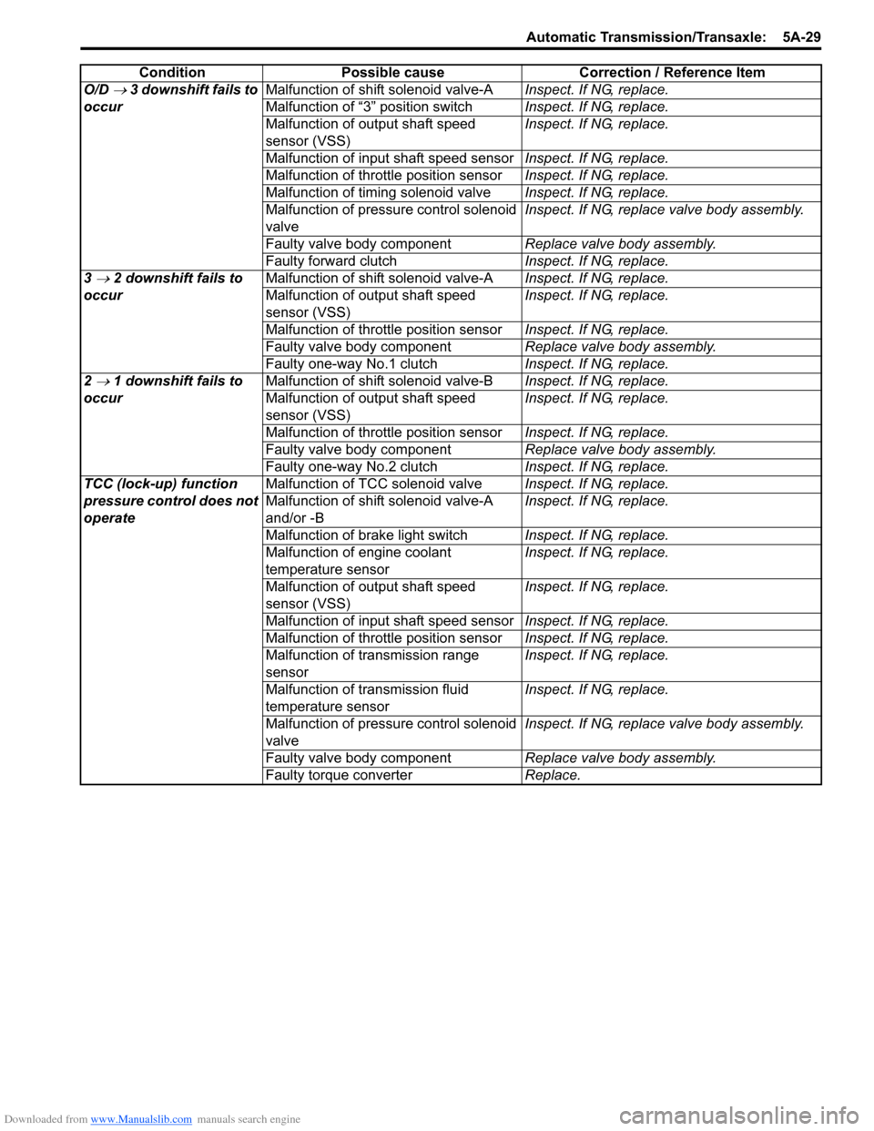
O/D → 3 downshift fails to
occurMalfunction of shift solenoid valve-AInspect. If NG, replace.
Malfunction of “3” position switchInspect. If NG, replace.
Malfunction of output shaft speed
sensor (VSS)Inspect. If NG, replace.
Malfunction of input shaft speed sensorInspect. If NG, replace.
Malfunction of throttle position sensorInspect. If NG, replace.
Malfunction of timing solenoid valveInspect. If NG, replace.
Malfunction of pressure control solenoid
valveInspect. If NG, replace valve body assembly.
Faulty valve body componentReplace valve body assembly.
Faulty forward clutchInspect. If NG, replace.
3
→ 2 downshift fails to
occurMalfunction of shift solenoid valve-AInspect. If NG, replace.
Malfunction of output shaft speed
sensor (VSS)Inspect. If NG, replace.
Malfunction of throttle position sensorInspect. If NG, replace.
Faulty valve body componentReplace valve body assembly.
Faulty one-way No.1 clutchInspect. If NG, replace.
2
→ 1 downshift fails to
occurMalfunction of shift solenoid valve-BInspect. If NG, replace.
Malfunction of output shaft speed
sensor (VSS)Inspect. If NG, replace.
Malfunction of throttle position sensorInspect. If NG, replace.
Faulty valve body componentReplace valve body assembly.
Faulty one-way No.2 clutchInspect. If NG, replace.
TCC (lock-up) function
pressure control does not
operateMalfunction of TCC solenoid valveInspect. If NG, replace.
Malfunction of shift solenoid valve-A
and/or -BInspect. If NG, replace.
Malfunction of brake light switchInspect. If NG, replace.
Malfunction of engine coolant
temperature sensorInspect. If NG, replace.
Malfunction of output shaft speed
sensor (VSS)Inspect. If NG, replace.
Malfunction of input shaft speed sensorInspect. If NG, replace.
Malfunction of throttle position sensorInspect. If NG, replace.
Malfunction of transmission range
sensorInspect. If NG, replace.
Malfunction of transmission fluid
temperature sensorInspect. If NG, replace.
Malfunction of pressure control solenoid
valveInspect. If NG, replace valve body assembly.
Faulty valve body componentReplace valve body assembly.
Faulty torque converterReplace. Condition Possible cause Correction / Reference Item
Page 685 of 1556

Downloaded from www.Manualslib.com manuals search engine Automatic Transmission/Transaxle: 5A-37
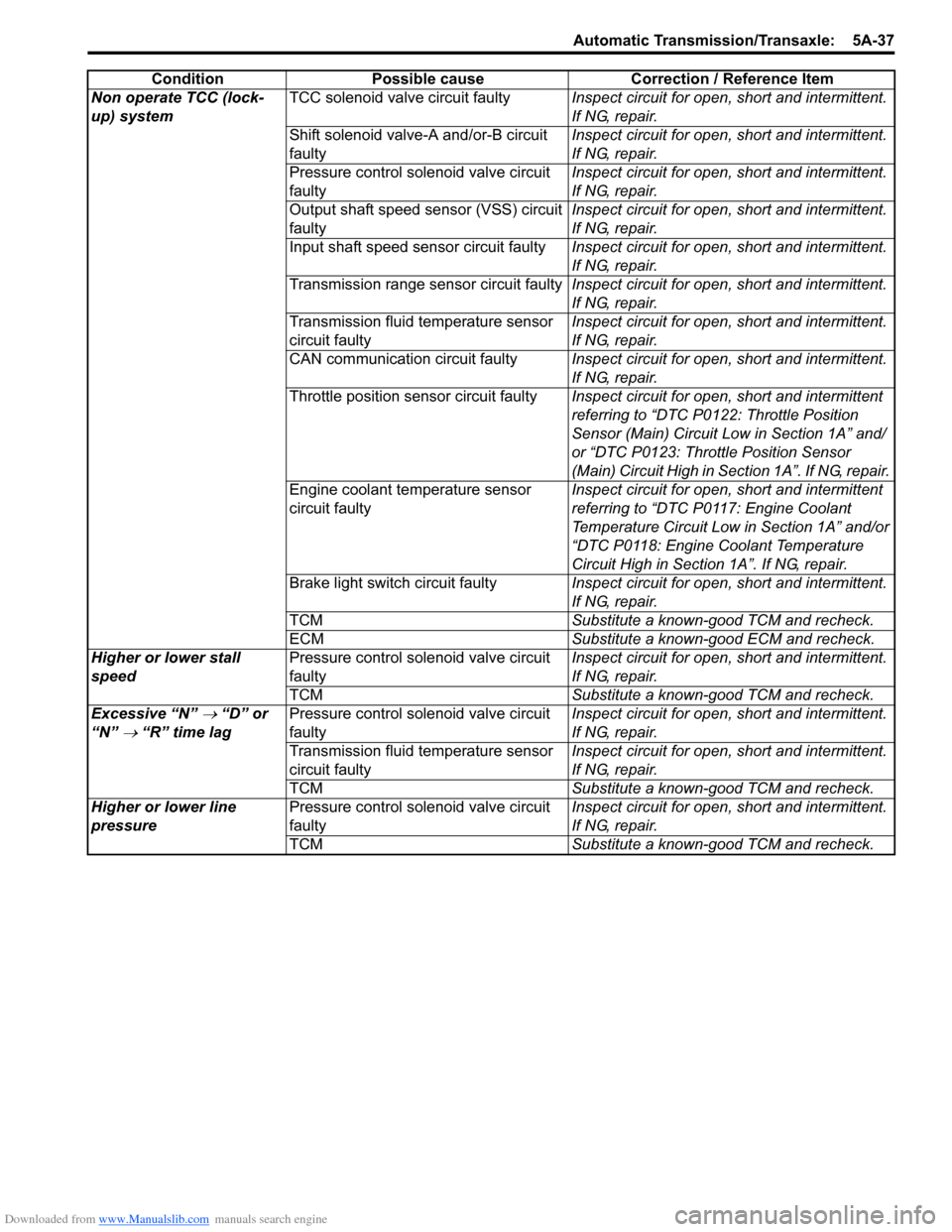
Non operate TCC (lock-
up) systemTCC solenoid valve circuit faultyInspect circuit for open, short and intermittent.
If NG, repair.
Shift solenoid valve-A and/or-B circuit
faultyInspect circuit for open, short and intermittent.
If NG, repair.
Pressure control solenoid valve circuit
faultyInspect circuit for open, short and intermittent.
If NG, repair.
Output shaft speed sensor (VSS) circuit
faulty Inspect circuit for open, short and intermittent.
If NG, repair.
Input shaft speed sensor circuit faulty Inspect circuit for open, short and intermittent.
If NG, repair.
Transmission range sensor circuit faultyInspect circuit for open, short and intermittent.
If NG, repair.
Transmission fluid temperature sensor
circuit faultyInspect circuit for open, short and intermittent.
If NG, repair.
CAN communication circuit faultyInspect circuit for open, short and intermittent.
If NG, repair.
Throttle position sensor circuit faultyInspect circuit for open, short and intermittent
referring to “DTC P0122: Throttle Position
Sensor (Main) Circuit Low in Section 1A” and/
or “DTC P0123: Throttle Position Sensor
(Main) Circuit High in Section 1A”. If NG, repair.
Engine coolant temperature sensor
circuit faultyInspect circuit for open, short and intermittent
referring to “DTC P0117: Engine Coolant
Temperature Circuit Low in Section 1A” and/or
“DTC P0118: Engine Coolant Temperature
Circuit High in Section 1A”. If NG, repair.
Brake light switch circuit faultyInspect circuit for open, short and intermittent.
If NG, repair.
TCMSubstitute a known-good TCM and recheck.
ECMSubstitute a known-good ECM and recheck.
Higher or lower stall
speedPressure control solenoid valve circuit
faultyInspect circuit for open, short and intermittent.
If NG, repair.
TCMSubstitute a known-good TCM and recheck.
Excessive “N”
→ “D” or
“N”
→ “R” time lagPressure control solenoid valve circuit
faultyInspect circuit for open, short and intermittent.
If NG, repair.
Transmission fluid temperature sensor
circuit faultyInspect circuit for open, short and intermittent.
If NG, repair.
TCMSubstitute a known-good TCM and recheck.
Higher or lower line
pressurePressure control solenoid valve circuit
faultyInspect circuit for open, short and intermittent.
If NG, repair.
TCMSubstitute a known-good TCM and recheck. Condition Possible cause Correction / Reference Item
Page 686 of 1556

Downloaded from www.Manualslib.com manuals search engine 5A-38 Automatic Transmission/Transaxle:
Trouble Diagnosis 2
On-vehicle repair
Condition Possible cause Correction / Reference Item
Unable to run in all rangeFaulty valve body componentReplace valve body assembly.
Excessive shift shockEngine abnormal conditionInspect and repair engine.
Malfunction of shift solenoid valve-A
and/or -BInspect. If NG, replace.
Malfunction of output shaft speed
sensor (VSS)Inspect. If NG, replace.
Malfunction of input shaft speed sensorInspect. If NG, replace.
Malfunction of transmission range
sensorInspect. If NG, replace.
Malfunction of transmission fluid
temperature sensorInspect. If NG, replace.
Malfunction of timing solenoid valve only
when N → D or 3 ↔ 4 shiftingInspect. If NG, replace.
Malfunction of pressure control solenoid
valveInspect. If NG, replace valve body assembly.
Malfunction of brake light switch except
N → D or N → R shiftingInspect referring to “Brake Light Switch
Inspection in Section 9B”. If NG, replace.
Malfunction of crankshaft position
sensorInspect referring to “Camshaft Position (CMP)
Sensor Inspection in Section 1C”. If NG,
replace.
Malfunction of Accelerator pedal
position (APP) sensorInspect referring to “Accelerator Pedal Position
(APP) Sensor Assembly On-Vehicle Inspection
in Section 1C”. If NG, replace.
Faulty valve body componentReplace valve body assembly.
Poor 1
→ 2 shiftMalfunction of shift solenoid valve-BInspect. If NG, replace.
Malfunction of output shaft speed
sensor (VSS)Inspect. If NG, replace.
Malfunction of transmission range
sensorInspect. If NG, replace.
Malfunction of Accelerator pedal
position (APP) sensorInspect referring to “Accelerator Pedal Position
(APP) Sensor Assembly On-Vehicle Inspection
in Section 1C”. If NG, replace.
Faulty valve body componentReplace valve body assembly.
Poor 2
→ 3 shiftMalfunction of shift solenoid valve-AInspect. If NG, replace.
Malfunction of output shaft speed
sensor (VSS)Inspect. If NG, replace.
Malfunction of transmission range
sensorInspect. If NG, replace.
Malfunction of Accelerator pedal
position (APP) sensorInspect referring to “Accelerator Pedal Position
(APP) Sensor Assembly On-Vehicle Inspection
in Section 1C”. If NG, replace.
Faulty valve body componentReplace valve body assembly.
Page 688 of 1556

Downloaded from www.Manualslib.com manuals search engine 5A-40 Automatic Transmission/Transaxle:
Trouble Diagnosis 3
Off-vehicle repairNon operate TCC (lock-
up) systemMalfunction of TCC solenoid valveInspect. If NG, replace.
Malfunction of shift solenoid valve-A
and/or -BInspect. If NG, replace.
Malfunction of output shaft speed
sensor (VSS)Inspect. If NG, replace.
Malfunction of input shaft speed sensorInspect. If NG, replace.
Malfunction of transmission range
sensorInspect. If NG, replace.
Malfunction of transmission fluid
temperature sensorInspect. If NG, replace.
Malfunction of pressure control solenoid
valveInspect. If NG, replace valve body assembly.
Malfunction of Accelerator pedal
position (APP) sensorInspect referring to “Accelerator Pedal Position
(APP) Sensor Assembly On-Vehicle Inspection
in Section 1C”. If NG, replace.
Malfunction of engine coolant
temperature sensorInspect referring to “Engine Coolant
Temperature (ECT) Sensor Inspection in
Section 1C”. If NG, replace.
Malfunction of brake light switchInspect referring to “Brake Light Switch
Inspection in Section 9B”. If NG, replace.
Faulty valve body componentReplace valve body assembly.
Excessive “N”
→ “D” or
“N”
→ “R” time lagMalfunction of transmission fluid
temperature sensorInspect. If NG, replace.
Pressure control solenoid valve circuit
faultyInspect. If NG, replace valve body assembly.
Clogged oil strainerReplace.
Faulty valve body componentReplace valve body assembly. Condition Possible cause Correction / Reference Item
Condition Possible cause Correction / Reference Item
Unable to run in all rangeFaulty oil pumpInspect. If NG, replace.
Seized or broken planetary gearInspect. If NG, replace.
Faulty one-way No.2 clutchInspect. If NG, replace.
Damaged drive plateInspect. If NG, replace.
Faulty forward clutchInspect. If NG, replace.
Faulty reverse clutchInspect. If NG, replace.
Faulty 1st and reverse brakeInspect. If NG, replace.
Faulty torque converterReplace.
Excessive “N”
→ “D” shift
shockFaulty forward clutchInspect. If NG, replace.
Excessive “N”
→ “R” shift
shockFaulty reverse clutchInspect. If NG, replace.
Faulty 1st and reverse brakeInspect. If NG, replace.
Poor 1
→ 2 shift,
excessive shock or
slippageFaulty 2nd brakeInspect. If NG, replace.
Faulty one-way No.1 clutchInspect. If NG, replace.
Poor 2
→ 3 shift,
excessive shock or
slippageFaulty direct clutchInspect. If NG, replace.
Poor 3
↔ O/D shift,
excessive shock or
slippageFaulty forward clutchInspect. If NG, replace.
Faulty O/D and 2nd coast brakeInspect. If NG, replace.
Poor 3
→ 2 shift,
excessive shock or
slippageFaulty direct clutchInspect. If NG, replace.
Faulty one-way No.1 clutchInspect. If NG, replace.
Poor 2
→ 1 shift,
excessive shock or
slippageFaulty 2nd brakeInspect. If NG, replace.
Faulty one-way No.2 clutchInspect. If NG, replace.
Page 689 of 1556

Downloaded from www.Manualslib.com manuals search engine Automatic Transmission/Transaxle: 5A-41
Transmission Warning Light Circuit Check – Light Remains “ON” at Ignition Switch ON (Non-Euro-
OBD Model)
S6RW0D5104054
Troubleshooting
Transmission Warning Light Circuit Check – Light Does Not Come “ON” at Ignition Switch ON (Non-
Euro-OBD Model)
S6RW0D5104055
TroubleshootingNon operate TCC (lock-
up) systemFaulty torque converterReplace.
Excessive “N”
→ “D” time
lagFaulty oil pumpInspect. If NG, replace.
Faulty forward clutchInspect. If NG, replace.
Faulty one-way No.2 clutchInspect. If NG, replace.
Leakage from “D” range fluid pressure
circuitOverhaul or replace valve body assembly.
Excessive “N”
→ “R” time
lagFaulty oil pumpInspect. If NG, replace.
Faulty reverse clutchInspect. If NG, replace.
Faulty 1st and reverse brakeInspect. If NG, replace.
Leakage from “R” range fluid pressure
circuitOverhaul or replace valve body assembly.
Poor engine brake in
downshift to “2” rangeFaulty O/D and 2nd coast brakeInspect. If NG, replace.
Poor engine brake in
downshift to “L” rangeFaulty 1st and reverse brakeInspect. If NG, replace. Condition Possible cause Correction / Reference Item
Step Action Yes No
1Diagnostic Trouble Code (DTC) Check
1) Check DTC referring to “DTC Check”.
Is there any DTC(s)?Perform DTC Flow to
repair and retry.Substitute a known-
good TCM and recheck.
If OK, substitute a
known-good
combination meter and
recheck.
Step Action Yes No
1Combination Meter Power Supply Check
1) Turn ignition switch ON.
Does other indicator / warning lights in combination meter
comes ON?Go to Step 2. Repair combination
meter power supply
circuit referring to
“Combination Meter
Circuit Diagram in
Section 9C”.
2 1) TCM power and ground circuit check referring to “TCM
Power and Ground Circuit Check”.
Is it in good condition?Go to Step 3. Repair or replace.
3DTC check
1) Check DTC referring to “DTC Check”.
Is there DTC U0073 or U0100?Go to applicable DTC
diag. flow.Go to Step 4.
4Combination Meter Function Check
1) Turn ignition switch ON.
Does A/T selector position indicator show correct select
lever position?Replace combination
meter.Substitute a known-
good TCM and recheck.
Page 794 of 1556

Downloaded from www.Manualslib.com manuals search engine 5A-146 Automatic Transmission/Transaxle:
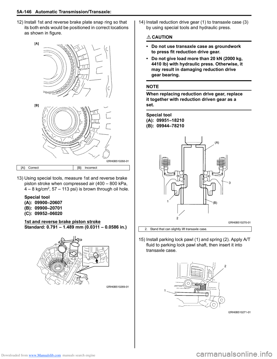
12) Install 1st and reverse brake plate snap ring so that
its both ends would be positioned in correct locations
as shown in figure.
13) Using special tools, measure 1st and reverse brake
piston stroke when compressed air (400 – 800 kPa,
4 – 8 kg/cm
2, 57 – 113 psi) is brown through oil hole.
Special tool
(A): 09900–20607
(B): 09900–20701
(C): 09952–06020
1st and reverse brake piston stroke
Standard: 0.791 – 1.489 mm (0.0311 – 0.0586 in.)14) Install reduction drive gear (1) to transaxle case (3)
by using special tools and hydraulic press.
CAUTION!
• Do not use transaxle case as groundwork
to press fit reduction drive gear.
• Do not give load more than 20 kN (2000 kg,
4410 lb) with hydraulic press. Otherwise, it
may result in damaging reduction drive
gear bearing.
NOTE
When replacing reduction drive gear, replace
it together with reduction driven gear as a
set.
Special tool
(A): 09951–18210
(B): 09944–78210
15) Install parking lock pawl (1) and spring (2). Apply A/T
fluid to parking lock pawl shaft, then insert it into
transaxle case.
[A]: Correct [B]: Incorrect
I2RH0B510268-01
I2RH0B510269-01
2. Stand that can slightly lift transaxle case.
I2RH0B510270-01
I2RH0B510271-01
Page 856 of 1556

Downloaded from www.Manualslib.com manuals search engine 5C-3 Clutch:
Repair Instructions
Clutch Pedal InspectionS6RW0D5306001
Cylinder Push Rod Play “a”
1) Press clutch pedal (1) gradually with finger, stop
when slight increase of resistance is felt and
measure how much pedal has moved (push rod
play) as represented by “a” as shown.
Push rod play
“a”: Max. 3 mm (0.12 in.)
2) If “a” is not within specification, replace master
cylinder (3) or pedal arm (2).
Clutch Pedal Free Travel “b”
1) Depress clutch pedal (1), stop the moment clutch
resistance is felt, and measure how much pedal has
moved (clutch pedal free travel) as represented by
“b” in the figure.
Clutch pedal free travel
“b”
: 2 – 8 mm (0.08 – 0.31 in.)
2) If “b” is not within specification, check pedal arm (2)
and master cylinder (3) and replace defective part.
Clutch Release Margin “c”
1) Pull up parking brake fully and block wheels.
2) Start engine and keep engine at idle with neutral
gear position.
3) Without clutch pedal (1) depressed, slightly push the
shift lever to reverse position until transaxle emits
gear contact noise. Do not shift the lever to reverse
position.
4) With emitting gear contact noise, be slow to depress
clutch pedal (1), and at gear contact noise died
position (release point) stop depressing.
5) Measure distance between release point (4) and full
stroke point (5) on clutch pedal (1) which is shown by
“c” in the figure.
Clutch release margin
“c”: 25 – 55 mm (0.98 – 2.17 in.)6) If “c” is not within specification, it is possible that air
is trapped in this system. If suspected so, bleed air
referring to “Air Bleeding of Clutch System”.Upon
completion of above inspection, start engine and
check clutch for proper operation.
Clutch Fluid Level InspectionS6RW0D5306002
Refer to “Brake Fluid Level Inspection in Section 4A”.
Clutch fluid specification
: Refer to the reservoir cap of the brake master
cylinder.
Air Bleeding of Clutch SystemS6RW0D5306003
CAUTION!
When operating the pedal stroke for air
bleeding of clutch system, after releasing the
clutch pedal, be sure to wait 1 second or
more before depressing it again. Otherwise,
the oil seal of operating cylinder will be
damaged, resulting in oil leakage.
Bleed air from clutch system.
Refer to “Air Bleeding of Brake System in Section 4A”.
I5RW0A530002-01