2006 SUZUKI SX4 ignition
[x] Cancel search: ignitionPage 1093 of 1556
Downloaded from www.Manualslib.com manuals search engine Air Bag System: 8B-54
DTC B1054 / B1058: Seat Belt Pretensioner Circuit Shorted to Power SupplyS6RW0D8204029
DTC B1054: Driver Seat Belt Pretensioner Circuit Shorted to Power Supply
DTC B1058: Passenger Seat Belt Pretensioner Circuit Shorted to Power Supply
Wiring Diagram
Refer to “DTC B1051 / B1055: Seat Belt Pretensioner Circuit High Resistance”.
DTC Detecting Condition and Trouble Area
DTC Troubleshooting
NOTE
Upon completion of inspection and repair work, perform the following items.
• Reconnect all air bag system components and ensure all components are properly mounted.
• Clear DTCs referring to “DTC Clearance”, if any.
• Repeat “Air Bag Diagnostic System Check” to confirm that the trouble has been corrected.
DTC detecting condition Trouble area
DTC B1054:
Driver seat belt pretensioner circuit has been shorted to
power supply for more than 4 sec.
DTC B1058:
Passenger seat belt pretensioner circuit has been shorted
to power supply for more than 4 sec.• Driver / passenger seat belt pretensioner circuit
•SDM
Step Action Yes No
1Was “Air Bag Diagnostic System Check Flow” performed?Go to Step 2. Go to “Air Bag
Diagnostic System
Check Flow”.
2Seat belt pretensioner circuit check
1) With ignition switch turned OFF, remove center pillar
lower trim of applicable side and disconnect applicable
seat belt pretensioner connector “L283” or “L285”.
2) Disconnect SDM connector “L04”.
3) Check for proper connection to applicable seat belt
pretensioner at terminals in “L283” or “L285”.
4) Check for proper connection to SDM at terminals “L04-7”
and “L04-8” (for DTC B1054) or terminals “L04-9” and
“L04-10” (for DTC B1058).
5) If OK, release shorting bar in SDM connector inserting
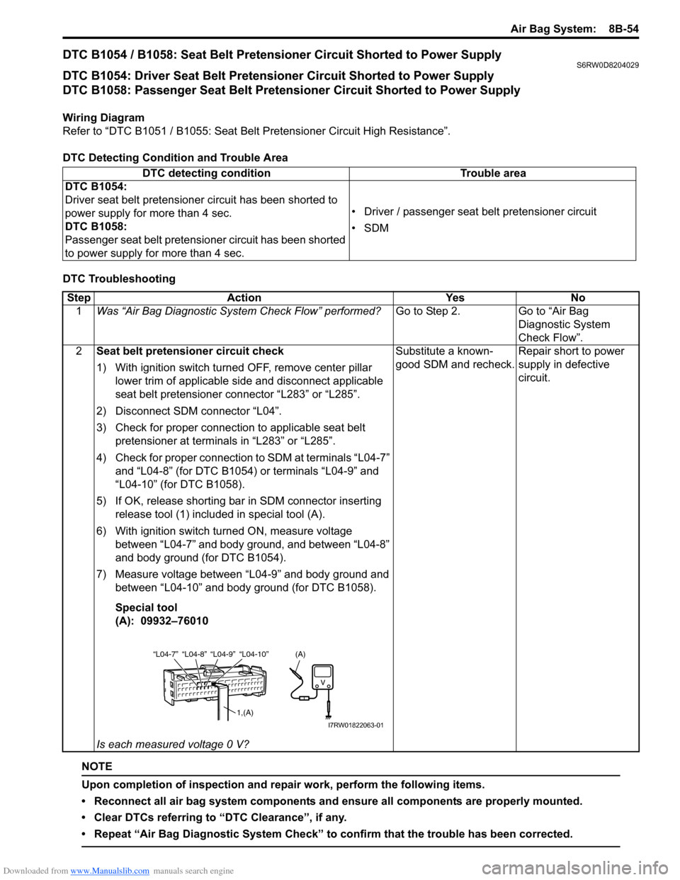
release tool (1) included in special tool (A).
6) With ignition switch turned ON, measure voltage
between “L04-7” and body ground, and between “L04-8”
and body ground (for DTC B1054).
7) Measure voltage between “L04-9” and body ground and
between “L04-10” and body ground (for DTC B1058).
Special tool
(A): 09932–76010
Is each measured voltage 0 V?Substitute a known-
good SDM and recheck.Repair short to power
supply in defective
circuit.
“L04-8” “L04-9” “L04-10” “L04-7”
1,(A)
(A)
I7RW01822063-01
Page 1094 of 1556
Downloaded from www.Manualslib.com manuals search engine 8B-55 Air Bag System:
DTC B1061 / B1065: Side-Air Bag Circuit High ResistanceS6RW0D8204053
DTC B1061: Driver Side-Air Bag Circuit High Resistance
DTC B1065: Passenger Side-Air Bag Circuit High Resistance
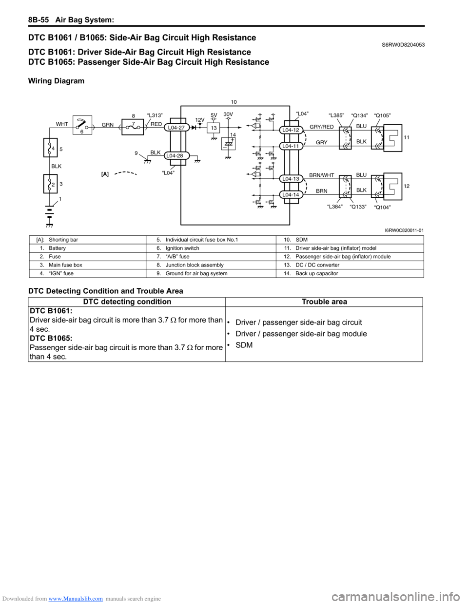
Wiring Diagram
DTC Detecting Condition and Trouble Area
“L04”[A]
BLK
L04-28
6 8
7
RED
GRN“L313”L04-27
910
13
12V5V30V
14
1
2 BLKWHT3
4
5
“L04”
GRY/RED
GRYBLU
BLK
BLU
BLK L04-12
L04-11
11 “Q134” “Q105” “L385”
BRN/WHT
BRN L04-13
L04-14
12
“Q104” “Q133” “L384”
I6RW0C820011-01
[A]: Shorting bar 5. Individual circuit fuse box No.1 10. SDM
1. Battery 6. Ignition switch 11. Driver side-air bag (inflator) model
2. Fuse 7. “A/B” fuse 12. Passenger side-air bag (inflator) module
3. Main fuse box 8. Junction block assembly 13. DC / DC converter
4. “IGN” fuse 9. Ground for air bag system 14. Back up capacitor
DTC detecting condition Trouble area
DTC B1061:
Driver side-air bag circuit is more than 3.7 Ω for more than
4 sec.
DTC B1065:
Passenger side-air bag circuit is more than 3.7 Ω for more
than 4 sec.• Driver / passenger side-air bag circuit
• Driver / passenger side-air bag module
•SDM
Page 1095 of 1556
Downloaded from www.Manualslib.com manuals search engine Air Bag System: 8B-56
DTC Troubleshooting
Step Action Yes No
1Was “Air Bag Diagnostic System Check Flow” performed?Go to Step 2. Go to “Air Bag
Diagnostic System
Check Flow”.
2Side-air bag circuit check
1) Remove applicable driver / passenger side-air bag
(inflator) module from seat back referring to “Side-Air
Bag (Inflator) Module Removal and Installation”.
2) Check for proper connection to applicable side-air bag
(inflator) module at terminal in connector “Q104” or
“Q105”.
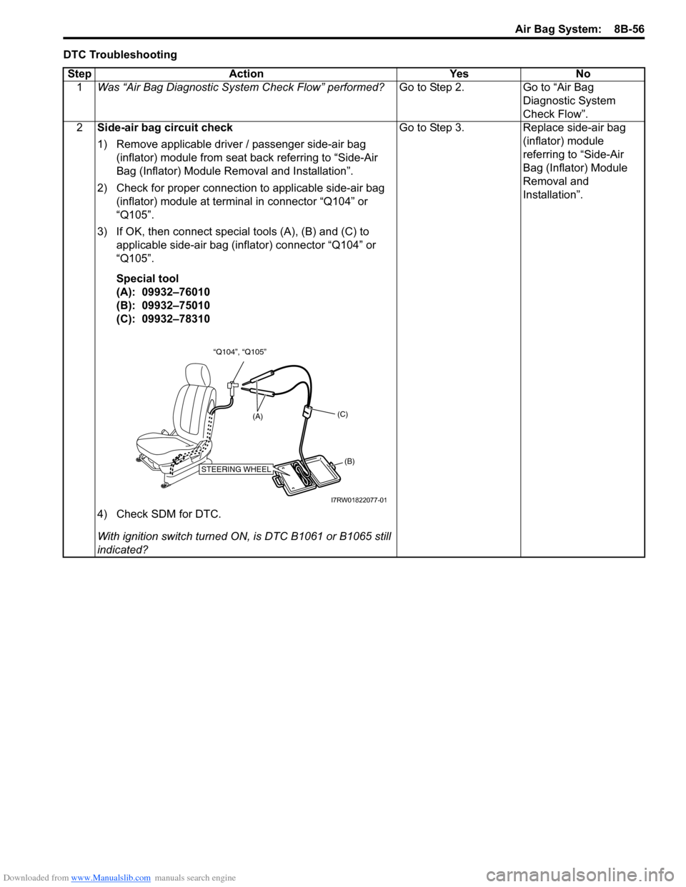
3) If OK, then connect special tools (A), (B) and (C) to
applicable side-air bag (inflator) connector “Q104” or
“Q105”.
Special tool
(A): 09932–76010
(B): 09932–75010
(C): 09932–78310
4) Check SDM for DTC.
With ignition switch turned ON, is DTC B1061 or B1065 still
indicated?Go to Step 3. Replace side-air bag
(inflator) module
referring to “Side-Air
Bag (Inflator) Module
Removal and
Installation”.
“Q104”, “Q105”
STEERING WHEEL(B) (C)
(A)
I7RW01822077-01
Page 1096 of 1556
Downloaded from www.Manualslib.com manuals search engine 8B-57 Air Bag System:
3Side-air bag circuit check
1) With ignition switch turned OFF, disconnect special tools
from applicable side-air bag (inflator) connector “Q104”
or “Q105”.
2) Disconnect SDM connector “L04”.
3) Check for proper connection to SDM connector at
terminal “L04-11” and “L04-12” (for DTC B1061) or
terminal “L04-13” and “L04-14” (for DTC B1065).
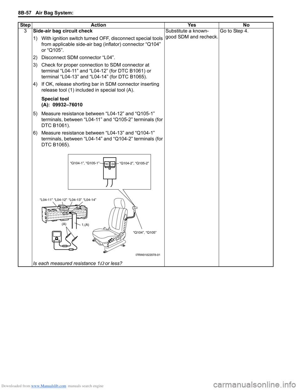
4) If OK, release shorting bar in SDM connector inserting
release tool (1) included in special tool (A).
Special tool
(A): 09932–76010
5) Measure resistance between “L04-12” and “Q105-1”
terminals, between “L04-11” and “Q105-2” terminals (for
DTC B1061).
6) Measure resistance between “L04-13” and “Q104-1”
terminals, between “L04-14” and “Q104-2” terminals (for
DTC B1065).
Is each measured resistance 1
Ω or less?Substitute a known-
good SDM and recheck.Go to Step 4. Step Action Yes No
(A)
“L04-12” “L04-13” “L04-14” “L04-11”
1,(A)
“Q104-1”, “Q105-1”
“Q104-2”, “Q105-2”
“Q104”, “Q105”
I7RW01822078-01
Page 1098 of 1556
Downloaded from www.Manualslib.com manuals search engine 8B-59 Air Bag System:
DTC B1062 / B1066: Side-Air Bag Circuit Low ResistanceS6RW0D8204054
DTC B1062: Driver Side-Air Bag Circuit Low Resistance
DTC B1066: Passenger Side-Air Bag Circuit Low Resistance
Wiring Diagram
Refer to “DTC B1061 / B1065: Side-Air Bag Circuit High Resistance”.
DTC Detecting Condition and Trouble Area
DTC TroubleshootingDTC detecting condition Trouble area
DTC B1062:
Driver side-air bag circuit is less than 1.0 Ω for more than
4 sec.
DTC B1066:
Passenger side-air bag circuit is less than 1.0 Ω for more
than 4 sec.• Driver / passenger side-air bag circuit
• Driver / passenger side-air bag module
•SDM
Step Action Yes No
1Was “Air Bag Diagnostic System Check Flow” performed?Go to Step 2. Go to “Air Bag
Diagnostic System
Check Flow”.
2Side-air bag circuit check
1) Remove applicable driver / passenger side-air bag
(inflator) module from seat back referring to “Side-Air
Bag (Inflator) Module Removal and Installation”.
2) Check for proper connection to applicable side-air bag
(inflator) module at terminal in connector “Q104” or
“Q105”.
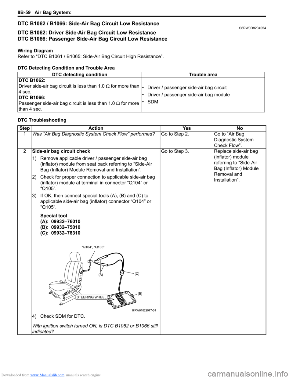
3) If OK, then connect special tools (A), (B) and (C) to
applicable side-air bag (inflator) connector “Q104” or
“Q105”.
Special tool
(A): 09932–76010
(B): 09932–75010
(C): 09932–78310
4) Check SDM for DTC.
With ignition switch turned ON, is DTC B1062 or B1066 still
indicated?Go to Step 3. Replace side-air bag
(inflator) module
referring to “Side-Air
Bag (Inflator) Module
Removal and
Installation”.
“Q104”, “Q105”
STEERING WHEEL(B) (C)
(A)
I7RW01822077-01
Page 1099 of 1556
Downloaded from www.Manualslib.com manuals search engine Air Bag System: 8B-60
3Side-air bag circuit check
1) With ignition switch turned OFF, disconnect special tools
from applicable side-air bag (inflator) connector “Q104”
or “Q105”.
2) Disconnect SDM connector “L04”.
3) Check for proper connection to SDM connector at
terminal “L04-11” and “L04-12” (for DTC B1062) or
terminal “L04-13” and “L04-14” (for DTC B1066).
4) If OK, release shorting bar in SDM connector inserting
release tool (1) included in special tool (A).
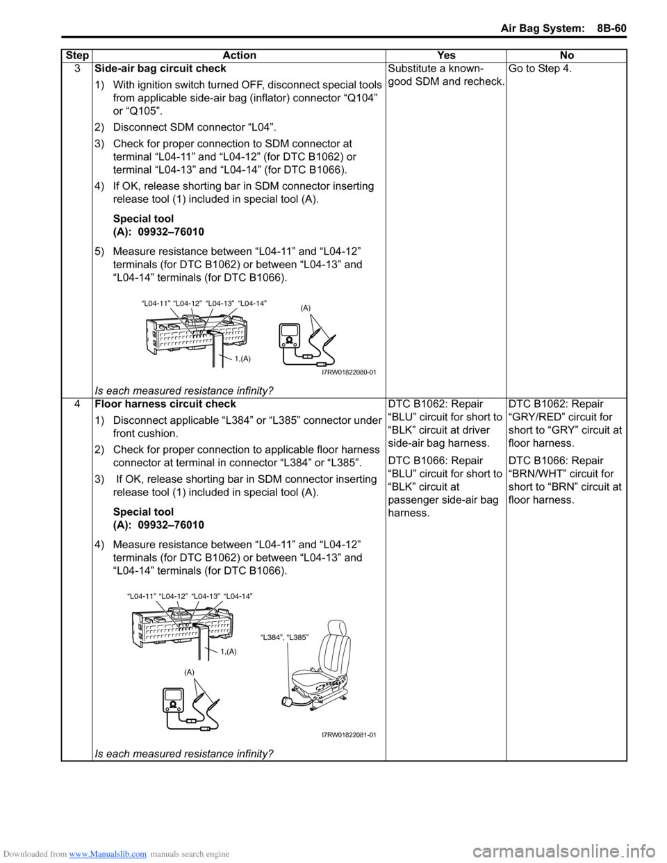
Special tool
(A): 09932–76010
5) Measure resistance between “L04-11” and “L04-12”
terminals (for DTC B1062) or between “L04-13” and
“L04-14” terminals (for DTC B1066).
Is each measured resistance infinity?Substitute a known-
good SDM and recheck.Go to Step 4.
4Floor harness circuit check
1) Disconnect applicable “L384” or “L385” connector under
front cushion.
2) Check for proper connection to applicable floor harness
connector at terminal in connector “L384” or “L385”.
3) If OK, release shorting bar in SDM connector inserting
release tool (1) included in special tool (A).
Special tool
(A): 09932–76010
4) Measure resistance between “L04-11” and “L04-12”
terminals (for DTC B1062) or between “L04-13” and
“L04-14” terminals (for DTC B1066).
Is each measured resistance infinity?DTC B1062: Repair
“BLU” circuit for short to
“BLK” circuit at driver
side-air bag harness.
DTC B1066: Repair
“BLU” circuit for short to
“BLK” circuit at
passenger side-air bag
harness.DTC B1062: Repair
“GRY/RED” circuit for
short to “GRY” circuit at
floor harness.
DTC B1066: Repair
“BRN/WHT” circuit for
short to “BRN” circuit at
floor harness. Step Action Yes No
(A)“L04-12” “L04-13” “L04-14” “L04-11”
1,(A)
I7RW01822080-01
“L384”, “L385”
(A)
“L04-12” “L04-13” “L04-14” “L04-11”
1,(A)
I7RW01822081-01
Page 1103 of 1556
Downloaded from www.Manualslib.com manuals search engine Air Bag System: 8B-64
DTC B1064 / B1068: Side-Air Bag Circuit Shorted to Power SupplyS6RW0D8204056
DTC B1064: Driver Side-Air Bag Circuit Shorted to Power Supply
DTC B1068: Passenger Side-Air Bag Circuit Shorted to Power Supply
Wiring Diagram
Refer to “DTC B1061 / B1065: Side-Air Bag Circuit High Resistance”.
DTC Detecting Condition and Trouble Area
DTC TroubleshootingDTC detecting condition Trouble area
DTC B1064:
Driver side-air bag circuit has been shorted to power
supply for more than 4 sec.
DTC B1068:
Passenger side-air bag circuit has been shorted to power
supply for more than 4 sec.• Driver / passenger side-air bag circuit
•SDM
Step Action Yes No
1Was “Air Bag Diagnostic System Check Flow” performed?Go to Step 2. Go to “Air Bag
Diagnostic System
Check Flow”.
2Side-air bag circuit check
1) Remove applicable driver / passenger side-air bag
(inflator) module from seat back referring to “Side-Air
Bag (Inflator) Module Removal and Installation”.
2) Disconnect SDM connector “L04”.
3) Check for proper connection to applicable side-air bag
(inflator) module at terminal in connector “Q104” or
“Q105”.
4) Check for proper connection to SDM connector at
terminal “L04-11” and “L04-12” (for DTC B1064) or
terminal “L04-13” and “L04-14” (for DTC B1068).
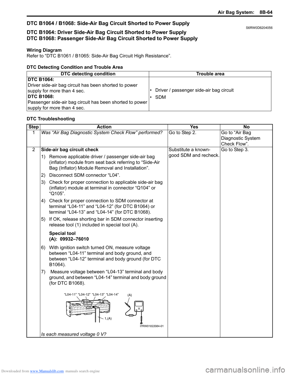
5) If OK, release shorting bar in SDM connector inserting
release tool (1) included in special tool (A).
Special tool
(A): 09932–76010
6) With ignition switch turned ON, measure voltage
between “L04-11” terminal and body ground, and
between “L04-12” terminal and body ground (for DTC
B1064).
7) Measure voltage between “L04-13” terminal and body
ground, and between “L04-14” terminal and body ground
(for DTC B1068).
Is each measured voltage 0 V?Substitute a known-
good SDM and recheck.Go to Step 3.
“L04-12” “L04-13” “L04-14” “L04-11”
1,(A)
(A)
I7RW01822084-01
Page 1104 of 1556
Downloaded from www.Manualslib.com manuals search engine 8B-65 Air Bag System:
NOTE
Upon completion of inspection and repair work, perform the following items.
• Reconnect all air bag system components, ensure all components are properly mounted.
• Clear DTCs referring to “DTC Clearance”, if any.
• Repeat “Air Bag Diagnostic System Check” to confirm that the trouble has been corrected.
3Floor harness circuit check
1) Disconnect applicable “L384” or “L385” connector under
front cushion.
2) Check for proper connection to applicable floor harness
connector at terminal in connector “L384” or “L385”.
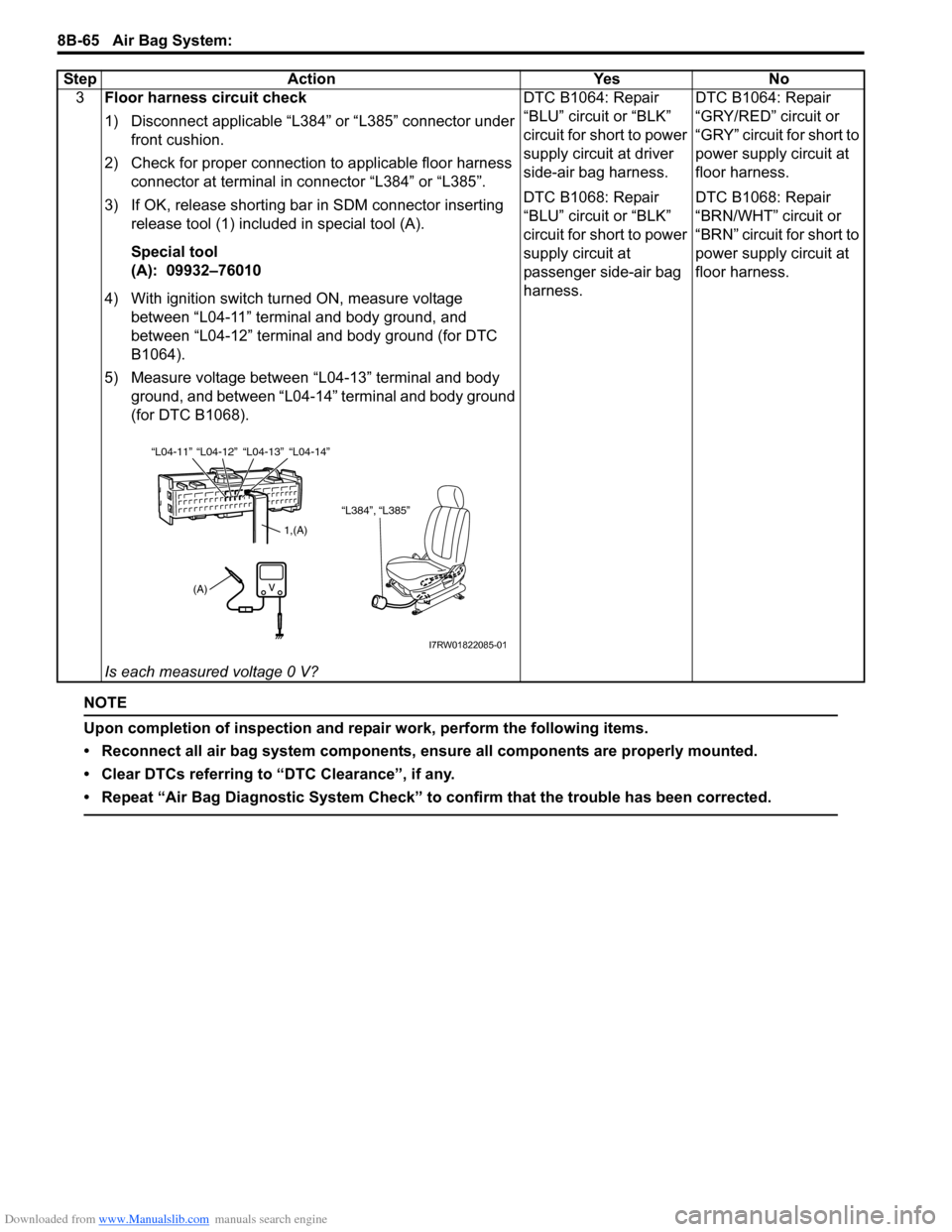
3) If OK, release shorting bar in SDM connector inserting
release tool (1) included in special tool (A).
Special tool
(A): 09932–76010
4) With ignition switch turned ON, measure voltage
between “L04-11” terminal and body ground, and
between “L04-12” terminal and body ground (for DTC
B1064).
5) Measure voltage between “L04-13” terminal and body
ground, and between “L04-14” terminal and body ground
(for DTC B1068).
Is each measured voltage 0 V?DTC B1064: Repair
“BLU” circuit or “BLK”
circuit for short to power
supply circuit at driver
side-air bag harness.
DTC B1068: Repair
“BLU” circuit or “BLK”
circuit for short to power
supply circuit at
passenger side-air bag
harness.DTC B1064: Repair
“GRY/RED” circuit or
“GRY” circuit for short to
power supply circuit at
floor harness.
DTC B1068: Repair
“BRN/WHT” circuit or
“BRN” circuit for short to
power supply circuit at
floor harness. Step Action Yes No
“L384”, “L385”
“L04-12” “L04-13” “L04-14” “L04-11”
1,(A)
(A)
I7RW01822085-01