2006 SUZUKI SX4 impact
[x] Cancel search: impactPage 1140 of 1556
Downloaded from www.Manualslib.com manuals search engine 8B-101 Air Bag System:
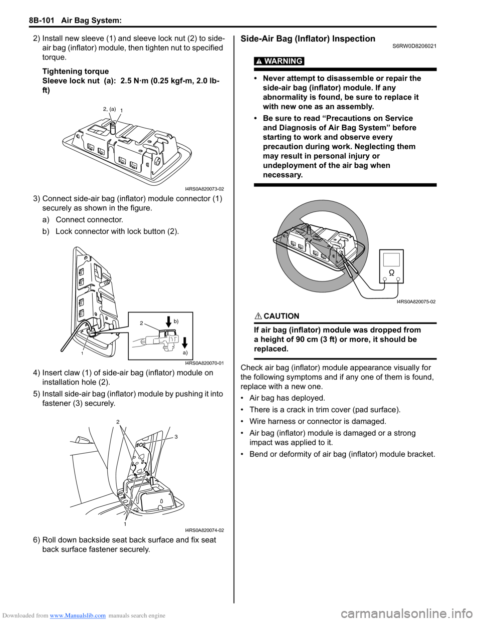
2) Install new sleeve (1) and sleeve lock nut (2) to side-
air bag (inflator) module, then tighten nut to specified
torque.
Tightening torque
Sleeve lock nut (a): 2.5 N·m (0.25 kgf-m, 2.0 lb-
ft)
3) Connect side-air bag (inflator) module connector (1)
securely as shown in the figure.
a) Connect connector.
b) Lock connector with lock button (2).
4) Insert claw (1) of side-air bag (inflator) module on
installation hole (2).
5) Install side-air bag (inflator) module by pushing it into
fastener (3) securely.
6) Roll down backside seat back surface and fix seat
back surface fastener securely.Side-Air Bag (Inflator) InspectionS6RW0D8206021
WARNING!
• Never attempt to disassemble or repair the
side-air bag (inflator) module. If any
abnormality is found, be sure to replace it
with new one as an assembly.
• Be sure to read “Precautions on Service
and Diagnosis of Air Bag System” before
starting to work and observe every
precaution during work. Neglecting them
may result in personal injury or
undeployment of the air bag when
necessary.
CAUTION!
If air bag (inflator) module was dropped from
a height of 90 cm (3 ft) or more, it should be
replaced.
Check air bag (inflator) module appearance visually for
the following symptoms and if any one of them is found,
replace with a new one.
• Air bag has deployed.
• There is a crack in trim cover (pad surface).
• Wire harness or connector is damaged.
• Air bag (inflator) module is damaged or a strong
impact was applied to it.
• Bend or deformity of air bag (inflator) module bracket.
12, (a)
I4RS0A820073-02
1
2
a) b)
I4RS0A820070-01
1
2
3
I4RS0A820074-02
I4RS0A820075-02
Page 1142 of 1556
Downloaded from www.Manualslib.com manuals search engine 8B-103 Air Bag System:
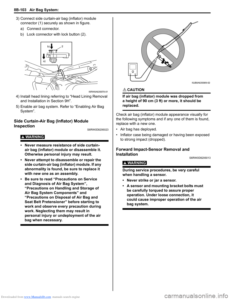
3) Connect side curtain-air bag (inflator) module
connector (1) securely as shown in figure.
a) Connect connector.
b) Lock connector with lock button (2).
4) Install head lining referring to “Head Lining Removal
and Installation in Section 9H”.
5) Enable air bag system. Refer to “Enabling Air Bag
System”.
Side Curtain-Air Bag (Inflator) Module
Inspection
S6RW0D8206023
WARNING!
• Never measure resistance of side curtain-
air bag (inflator) module or disassemble it.
Otherwise personal injury may result.
• Never attempt to disassemble or repair the
side curtain-air bag (inflator) module. If any
abnormality is found, be sure to replace it
with new one as an assembly.
• Be sure to read “Precautions on Service
and Diagnosis of Air Bag System”,
“Precautions on Handling and Storage of
Air Bag System Components” and
“Precautions on Disposal of Air Bag and
Seat Belt Pretensioner” before starting to
work and observe every precaution during
work. Neglecting them may result in
personal injury or undeployment of the air
bag when necessary.
CAUTION!
If air bag (inflator) module was dropped from
a height of 90 cm (3 ft) or more, it should be
replaced.
Check air bag (inflator) module appearance visually for
the following symptoms and if any one of them is found,
replace with a new one.
• Air bag has deployed.
• Inflator case being damaged or having been exposed
to strong impact (dropped).
Forward Impact-Sensor Removal and
Installation
S6RW0D8206013
WARNING!
During service procedures, be very careful
when handling a sensor.
• Never strike or jar a sensor.
• A sensor and mounting bracket bolts must
be carefully torqued to assure proper
operation. Under loose connection, it
could cause improper operation of the air
bag system.
1
2
b)
a)
I5RW0A820078-01
I5JB0A820089-02
Page 1143 of 1556
Downloaded from www.Manualslib.com manuals search engine Air Bag System: 8B-104
Removal
1) Disconnect negative (–) cable at battery.
2) Disable air bag system referring to “Disabling Air
Bag System”.
3) Remove front bumper referring to “Front Bumper
and Rear Bumper Components in Section 9K”.
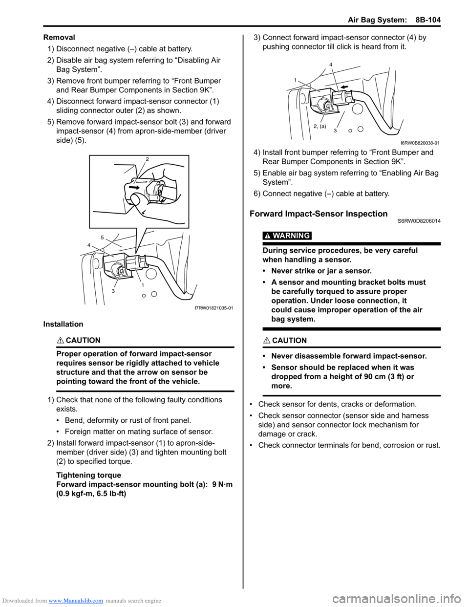
4) Disconnect forward impact-sensor connector (1)
sliding connector outer (2) as shown.
5) Remove forward impact-sensor bolt (3) and forward
impact-sensor (4) from apron-side-member (driver
side) (5).
Installation
CAUTION!
Proper operation of forward impact-sensor
requires sensor be rigidly attached to vehicle
structure and that the arrow on sensor be
pointing toward the front of the vehicle.
1) Check that none of the following faulty conditions
exists.
• Bend, deformity or rust of front panel.
• Foreign matter on mating surface of sensor.
2) Install forward impact-sensor (1) to apron-side-
member (driver side) (3) and tighten mounting bolt
(2) to specified torque.
Tightening torque
Forward impact-sensor mounting bolt (a): 9 N·m
(0.9 kgf-m, 6.5 lb-ft)3) Connect forward impact-sensor connector (4) by
pushing connector till click is heard from it.
4) Install front bumper referring to “Front Bumper and
Rear Bumper Components in Section 9K”.
5) Enable air bag system referring to “Enabling Air Bag
System”.
6) Connect negative (–) cable at battery.
Forward Impact-Sensor InspectionS6RW0D8206014
WARNING!
During service procedures, be very careful
when handling a sensor.
• Never strike or jar a sensor.
• A sensor and mounting bracket bolts must
be carefully torqued to assure proper
operation. Under loose connection, it
could cause improper operation of the air
bag system.
CAUTION!
• Never disassemble forward impact-sensor.
• Sensor should be replaced when it was
dropped from a height of 90 cm (3 ft) or
more.
• Check sensor for dents, cracks or deformation.
• Check sensor connector (sensor side and harness
side) and sensor connector lock mechanism for
damage or crack.
• Check connector terminals for bend, corrosion or rust.
4
2
3
5
1
I7RW01821035-01
1
2, (a)
4
3
I6RW0B820038-01
Page 1144 of 1556
Downloaded from www.Manualslib.com manuals search engine 8B-105 Air Bag System:
Side Impact-Sensor Removal and InstallationS6RW0D8206024
WARNING!
During service procedures, be very careful
when handling a sensor.
• Never strike or jar a sensor.
• A sensor bolt must be carefully torqued to
assure proper operation. Under loose
connection, it could cause improper
operation of the air bag system.
Removal
1) Disconnect negative (–) cable at battery.
2) Disable air bag system. Refer to “Disabling Air Bag
System”.
3) Remove center pillar lower trim.
4) Turn up floor carpet at front seat side.
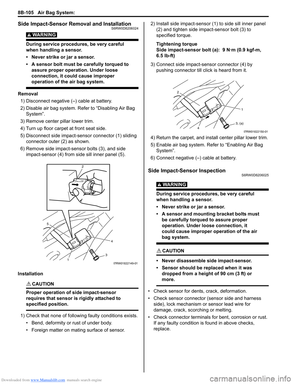
5) Disconnect side impact-sensor connector (1) sliding
connector outer (2) as shown.
6) Remove side impact-sensor bolts (3), and side
impact-sensor (4) from side sill inner panel (5).
Installation
CAUTION!
Proper operation of side impact-sensor
requires that sensor is rigidly attached to
specified position.
1) Check that none of following faulty conditions exists.
• Bend, deformity or rust of under body.
• Foreign matter on mating surface of sensor.2) Install side impact-sensor (1) to side sill inner panel
(2) and tighten side impact-sensor bolt (3) to
specified torque.
Tightening torque
Side impact-sensor bolt (a): 9 N·m (0.9 kgf-m,
6.5 lb-ft)
3) Connect side impact-sensor connector (4) by
pushing connector till click is heard from it.
4) Return the carpet, and install center pillar lower trim.
5) Enable air bag system. Refer to “Enabling Air Bag
System”.
6) Connect negative (–) cable at battery.
Side Impact-Sensor InspectionS6RW0D8206025
WARNING!
During service procedures, be very careful
when handling a sensor.
• Never strike or jar a sensor.
• A sensor and mounting bracket bolts must
be carefully torqued to assure proper
operation. Under loose connection, it
could cause improper operation of the air
bag system.
CAUTION!
• Never disassemble side impact-sensor.
• Sensor should be replaced when it was
dropped from a height of 90 cm (3 ft) or
more.
• Check sensor for dents, crack, deformation.
• Check sensor connector (sensor side and harness
side), lock mechanism or sensor lead wire for
damage, crack, scorching or melting.
• Check connector terminals for bent, corrosion or rust.
If any faulty condition is found in above checks,
replace.
5
4
3
2
1I7RW01822149-01
2
1
3, (a)
4I7RW01822150-01
Page 1157 of 1556
Downloaded from www.Manualslib.com manuals search engine Air Bag System: 8B-118
Specifications
Tightening Torque SpecificationsS6RW0D8207001
NOTE
The specified tightening torque is also described in the following.
“Side-Air Bag (Inflator) Module Removal and Installation”
Reference:
For the tightening torque of fastener not specified in this section, refer to “Fasteners Information in Section 0A”.
Special Tools and Equipment
Use of Special ToolsS6RW0D8208001
WARNING!
To avoid deployment when troubleshooting
the air bag system, do not use electrical
equipment such as a battery powered or AC
powered voltmeter, ohmmeter, etc., or any
type of electrical equipment other than that
specified. Do not use a non-powered probe
type tester.
Instructions must be followed carefully,
otherwise personal injury may result.
You should be familiar with the tools listed under the
heading “Special Tool”. You should be able to measure
voltage and resistance. You should be familiar with
proper use of a scan tool such as Air Bag Driver /
Passenger Load Tool, Connector Test Adapter Kit and
the Digital Multimeter.
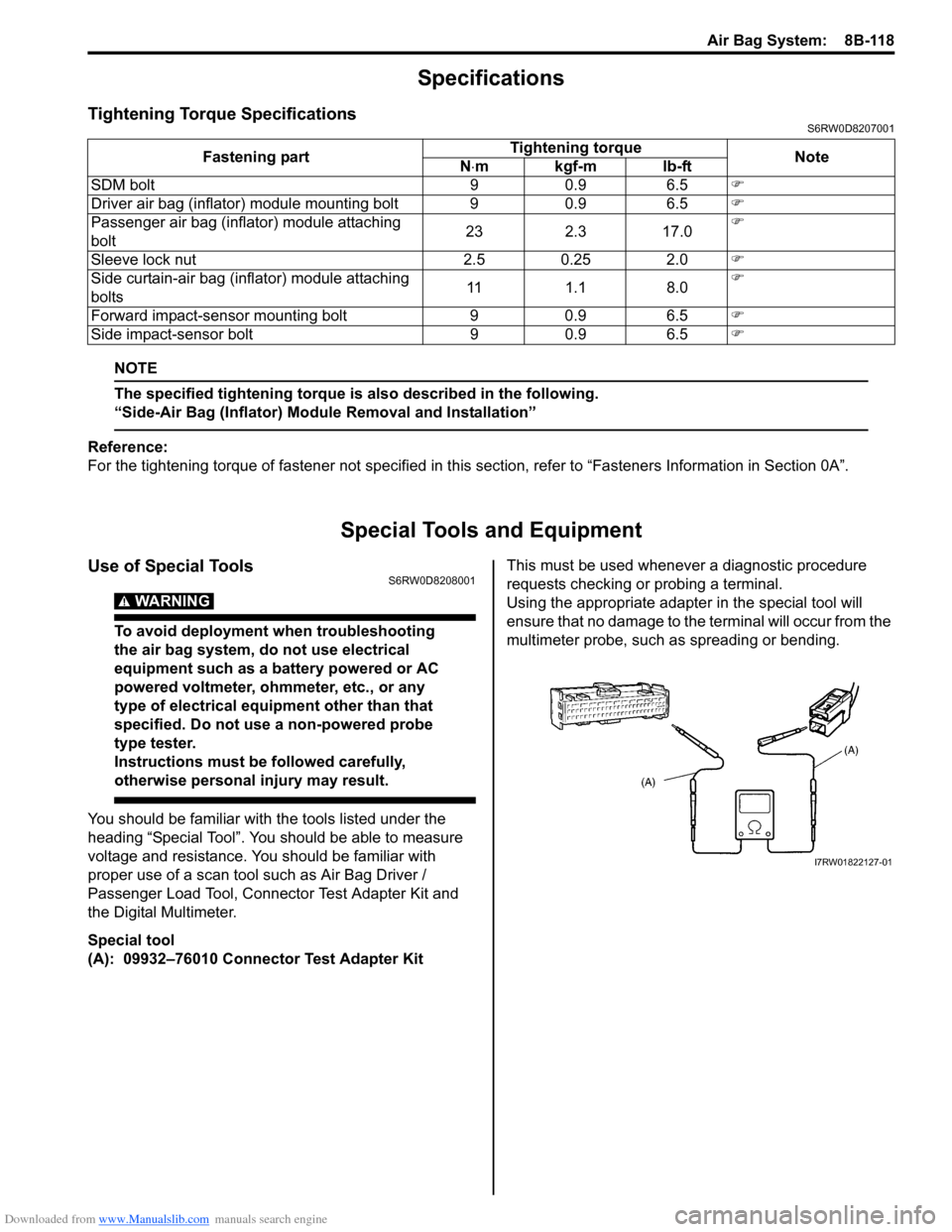
Special tool
(A): 09932–76010 Connector Test Adapter KitThis must be used whenever a diagnostic procedure
requests checking or probing a terminal.
Using the appropriate adapter in the special tool will
ensure that no damage to the terminal will occur from the
multimeter probe, such as spreading or bending. Fastening partTightening torque
Note
N⋅mkgf-mlb-ft
SDM bolt 9 0.9 6.5�)
Driver air bag (inflator) module mounting bolt 9 0.9 6.5�)
Passenger air bag (inflator) module attaching
bolt23 2.3 17.0�)
Sleeve lock nut 2.5 0.25 2.0�)
Side curtain-air bag (inflator) module attaching
bolts11 1.1 8.0�)
Forward impact-sensor mounting bolt 9 0.9 6.5�)
Side impact-sensor bolt 9 0.9 6.5�)
I7RW01822127-01
Page 1386 of 1556
Downloaded from www.Manualslib.com manuals search engine 9E-1 Glass / Windows / Mirrors:
Body, Cab and Accessories
Glass / Windows / Mirrors
Precautions
Precautions for Power Window Service (Pinching Prevention Function Model)S6RW0D9500001
WARNING!
When checking the pinching prevention function, never attempt intentionally to have your hand, arm
or any other part of the body pinched. Also, use full care not to have your body caught.
• Do not drop the power window regulator (motor) or expose it to a strong impact in any other way.
• Do not operate the motor unless the power window regulator (motor) is installed and ready to operate door glass.
• If any peripheral part has bean damaged, replace regulator (motor) as well depending on the damage condition.
• After replacing or disconnecting the driver side power window regulator (motor), power window main switch, battery
and/or fuse, make sure to execute the initial setting, (to have the door glass closed position learned) refer to “Power
Window Main Switch Initialization (Pinching Prevention Function Model)”.
General Description
Rear End Door Window Defogger System DescriptionS6RW0D9501001
The rear end door window defogger is controlled by BCM. For the BCM description refer to “BCM General Description
in Section 10B”.