2006 SUZUKI SX4 ECO mode
[x] Cancel search: ECO modePage 1121 of 1556
Downloaded from www.Manualslib.com manuals search engine Air Bag System: 8B-82
NOTE
Upon completion of inspection and repair work, perform the following items.
• Reconnect all air bag system components, ensure all components are properly mounted.
• Clear DTCs referring to “DTC Clearance”, if any.
• Repeat “Air Bag Diagnostic System Check” to confirm that the trouble has been corrected.
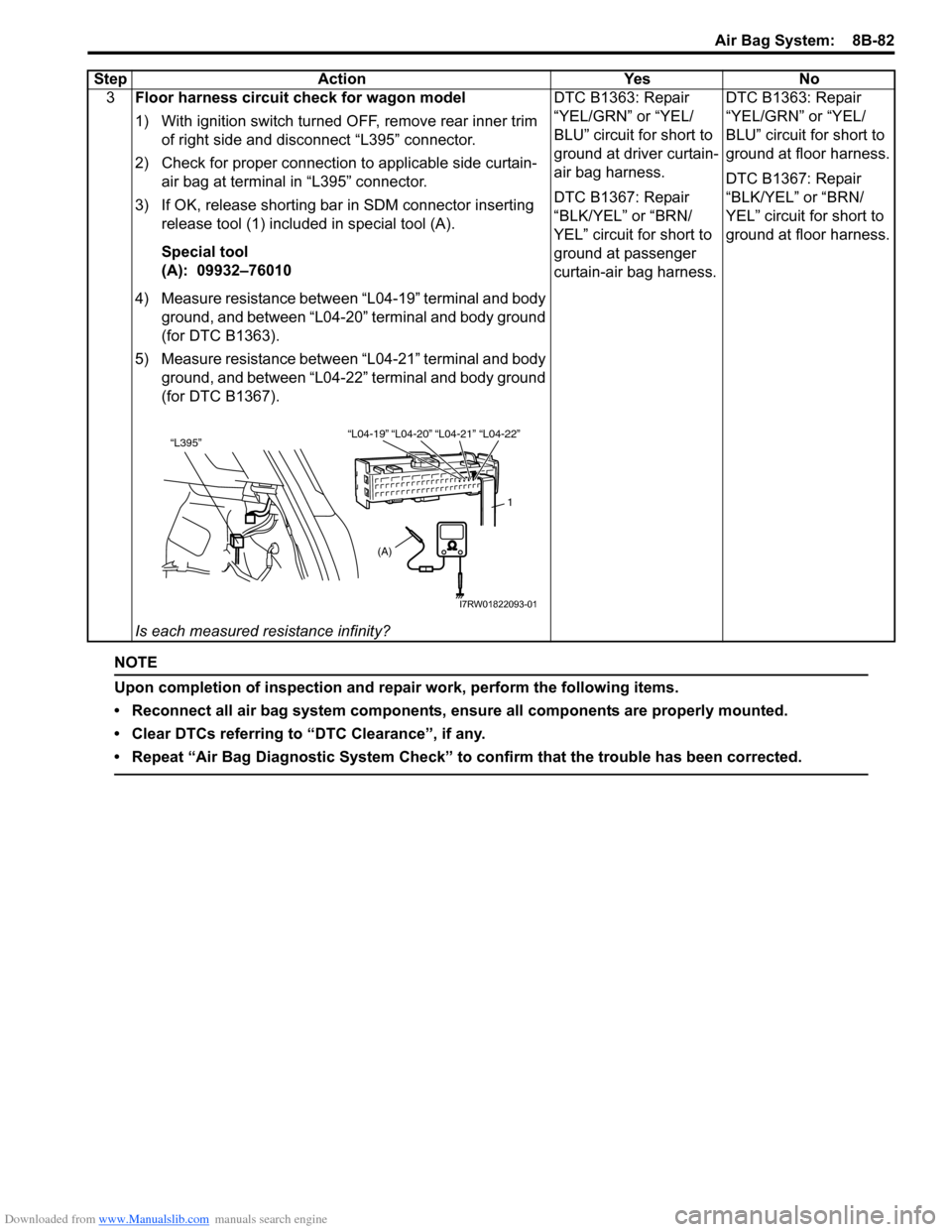
3Floor harness circuit check for wagon model
1) With ignition switch turned OFF, remove rear inner trim
of right side and disconnect “L395” connector.
2) Check for proper connection to applicable side curtain-
air bag at terminal in “L395” connector.
3) If OK, release shorting bar in SDM connector inserting
release tool (1) included in special tool (A).
Special tool
(A): 09932–76010
4) Measure resistance between “L04-19” terminal and body
ground, and between “L04-20” terminal and body ground
(for DTC B1363).
5) Measure resistance between “L04-21” terminal and body
ground, and between “L04-22” terminal and body ground
(for DTC B1367).
Is each measured resistance infinity?DTC B1363: Repair
“YEL/GRN” or “YEL/
BLU” circuit for short to
ground at driver curtain-
air bag harness.
DTC B1367: Repair
“BLK/YEL” or “BRN/
YEL” circuit for short to
ground at passenger
curtain-air bag harness.DTC B1363: Repair
“YEL/GRN” or “YEL/
BLU” circuit for short to
ground at floor harness.
DTC B1367: Repair
“BLK/YEL” or “BRN/
YEL” circuit for short to
ground at floor harness. Step Action Yes No
“L04-20” “L04-21” “L04-19”“L04-22”“L395”
1
(A)
I7RW01822093-01
Page 1123 of 1556
Downloaded from www.Manualslib.com manuals search engine Air Bag System: 8B-84
NOTE
Upon completion of inspection and repair work, perform the following items.
• Reconnect all air bag system components, ensure all components are properly mounted.
• Clear DTCs referring to “DTC Clearance”, if any.
• Repeat “Air Bag Diagnostic System Check” to confirm that the trouble has been corrected.
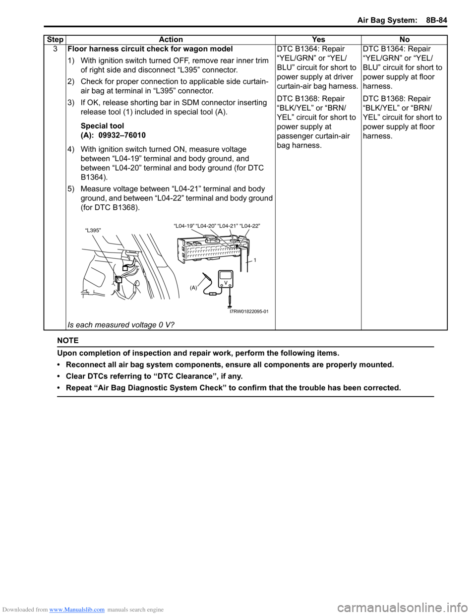
3Floor harness circuit check for wagon model
1) With ignition switch turned OFF, remove rear inner trim
of right side and disconnect “L395” connector.
2) Check for proper connection to applicable side curtain-
air bag at terminal in “L395” connector.
3) If OK, release shorting bar in SDM connector inserting
release tool (1) included in special tool (A).
Special tool
(A): 09932–76010
4) With ignition switch turned ON, measure voltage
between “L04-19” terminal and body ground, and
between “L04-20” terminal and body ground (for DTC
B1364).
5) Measure voltage between “L04-21” terminal and body
ground, and between “L04-22” terminal and body ground
(for DTC B1368).
Is each measured voltage 0 V?DTC B1364: Repair
“YEL/GRN” or “YEL/
BLU” circuit for short to
power supply at driver
curtain-air bag harness.
DTC B1368: Repair
“BLK/YEL” or “BRN/
YEL” circuit for short to
power supply at
passenger curtain-air
bag harness.DTC B1364: Repair
“YEL/GRN” or “YEL/
BLU” circuit for short to
power supply at floor
harness.
DTC B1368: Repair
“BLK/YEL” or “BRN/
YEL” circuit for short to
power supply at floor
harness. Step Action Yes No
“L04-20” “L04-21” “L04-19”“L04-22”“L395”
1
(A)
I7RW01822095-01
Page 1164 of 1556
Downloaded from www.Manualslib.com manuals search engine 9-iv Table of Contents
Front Speaker Removal and Installation (If
Equipped) ........................................................9C-19
Rear Speaker Removal and Installation (If
Equipped) ........................................................9C-19
GPS Antenna Removal and Installation (If
Equipped) ........................................................9C-20
Horn Removal and Installation ..........................9C-20
Horn Inspection .................................................9C-20
Horn Relay Inspection .......................................9C-20
Antenna Base Removal and Installation ...........9C-21
Remote Audio Control Switch Removal and
Installation (If Equipped) .................................9C-21
Remote Audio Control Switch Inspection (If
Equipped) ........................................................9C-22
Vehicle Speed Signal Inspection (For Audio
Unit) (If Equipped) ...........................................9C-22
Specifications .....................................................9C-22
Tightening Torque Specifications ......................9C-22
Wipers / Washers .................................... 9D-1
Diagnostic Information and Procedures ............ 9D-1
Front Wiper and Washer Symptom Diagnosis ....9D-1
Rear Wiper and Washer Symptom Diagnosis..... 9D-1
Repair Instructions ..............................................9D-2
Wipers and Washers Components .....................9D-2
Washer Tank and Washer Pump Removal
and Installation ..................................................9D-3
Washer Pump Inspection ....................................9D-3
Windshield Wiper Removal and Installation ........9D-3
Windshield Wiper Motor Inspection.....................9D-4
Rear Wiper Removal and Installation.................. 9D-6
Rear Wiper Motor Inspection ..............................9D-7
Windshield Wiper and Washer Switch
Removal and Installation ................................... 9D-8
Windshield Wiper and Washer Switch
Inspection .......................................................... 9D-8
Rear Wiper and Washer Switch Removal and
Installation .......................................................9D-10
Rear Wiper and Washer Switch Inspection.......9D-10
Rear Wiper Relay Removal and Installation .....9D-10
Rear Wiper Relay Inspection ............................9D-10
Specifications .....................................................9D-11
Tightening Torque Specifications ......................9D-11
Glass / Windows / Mirrors .......................9E-1
Precautions........................................................... 9E-1
Precautions for Power Window Service
(Pinching Prevention Function Model) .............. 9E-1
General Description ............................................. 9E-1
Rear End Door Window Defogger System
Description ........................................................ 9E-1
Schematic and Routing Diagram ........................ 9E-2
Power Window Circuit Diagram (Pinching
Prevention Function Model) .............................. 9E-2
Diagnostic Information and Procedures ............ 9E-3
Rear End door Window Defogger Symptom
Diagnosis .......................................................... 9E-3
Power Window Control System Symptom
Diagnosis .......................................................... 9E-3Inspection of Pinching Prevention Function
(Pinching Prevention Function Model) .............. 9E-4
Power Door Mirror Control System Symptom
Diagnosis .......................................................... 9E-4
Door Mirror Heater Symptom Diagnosis (If
Equipped) .......................................................... 9E-5
Repair Instructions .............................................. 9E-5
Windshield Components ..................................... 9E-5
Windshield Removal and Installation .................. 9E-6
Front Pillar Window Components...................... 9E-10
Front Pillar Window Removal and Installation... 9E-10
Rear Quarter Window Components .................. 9E-11
Rear Quarter Window Removal and
Installation ....................................................... 9E-11
Rear End Door Window Components ............... 9E-12
Rear End Door Glass Removal and
Installation ....................................................... 9E-12
Front Door Window Components ...................... 9E-13
Front Door Glass Removal and Installation ...... 9E-14
Front Door Window Regulator Removal and
Installation ....................................................... 9E-15
Front Door Window Regulator Inspection ......... 9E-15
Rear Door Window Components ...................... 9E-16
Rear Door Glass Removal and Installation ....... 9E-16
Rear Door Window Regulator Removal and
Installation ....................................................... 9E-18
Rear Door Window Regulator Inspection .......... 9E-18
Rear End Door Window Defogger Switch
Inspection ........................................................ 9E-18
Rear End Door Window Defogger Relay
Inspection ........................................................ 9E-19
Rear End Door Window Defogger Wire
Inspection ........................................................ 9E-19
Rear End Door Window Defogger Wire
Repair.............................................................. 9E-20
Power Window Main Switch Inspection ............ 9E-20
Power Window Sub Switch Inspection .............. 9E-22
Pulse Sensor and Its Circuit Inspection
(Pinching Prevention Function Model) ............ 9E-23
Power Window Main Switch Initialization
(Pinching Prevention Function Model) ............ 9E-24
Door Mirror Components................................... 9E-24
Door Mirror Removal and Installation................ 9E-25
Power Door Mirror Switch Inspection ................ 9E-25
Power Door Mirror Actuator Inspection ............. 9E-25
Door Mirror Heater Inspection (If Equipped) ..... 9E-26
Door Mirror Heater Switch Inspection (If
Equipped) ........................................................ 9E-26
Special Tools and Equipment ........................... 9E-26
Recommended Service Material ....................... 9E-26
Security and Locks...................................9F-1
General Description ............................................. 9F-1
Key Coding Construction .................................... 9F-1
Rear End Door Opener System Description ....... 9F-1
Component Location ........................................... 9F-2
Power Door Lock and Keyless Entry System
Component Location (If Equipped) ................... 9F-2
Diagnostic Information and Procedures ............ 9F-3
Page 1165 of 1556
Downloaded from www.Manualslib.com manuals search engine Table of Contents 9-v
Power Door Lock System Symptom
Diagnosis (If Equipped)..................................... 9F-3
Power Door Lock System Operation
Inspection (If Equipped) .................................... 9F-3
Keyless Entry System Symptom Diagnosis (If
Equipped).......................................................... 9F-4
Keyless Entry System Operation Inspection
(If Equipped) ..................................................... 9F-5
Door Lock Function of Keyless Start System
Symptom Diagnosis (If Equipped) .................... 9F-5
Rear End Door Opener System Symptom
Diagnosis (If Equipped)..................................... 9F-5
Rear End Door Opener System Operation
Inspection (If Equipped) .................................... 9F-5
Repair Instructions .............................................. 9F-6
Front Door Lock Assembly Components ............ 9F-6
Front Door Lock Assembly Removal and
Installation ......................................................... 9F-6
Front Door Lock Assembly Inspection ................ 9F-8
Power Door Lock Switch Inspection (If
Equipped).......................................................... 9F-8
Door Key Cylinder Switch Inspection (If
Equipped).......................................................... 9F-8
Power Door Lock Actuator Inspection (If
Equipped).......................................................... 9F-9
Rear Door Lock Assembly Components ........... 9F-10
Rear Door Lock Assembly Removal and
Installation ....................................................... 9F-10
Rear Door Lock Assembly Inspection ............... 9F-10
Rear End Door Lock Assembly Components.... 9F-11
Rear End Door Lock Assembly Removal and
Installation ....................................................... 9F-12
Rear End Door Lock Assembly Inspection........ 9F-12
Rear End Door Opener Switch Inspection (If
Equipped)........................................................ 9F-12
Replacement of Transmitter Battery (Other
than Keyless Start Model) ............................... 9F-13
Programming Transmitter Code for Keyless
Entry System (Other than Keyless Start
Model) ............................................................. 9F-13
Keyless Entry Answer Back Function
Change-over Procedure (If Equipped) ............ 9F-14
Keyless Entry Receiver Removal and
Installation (If Equipped)................................. 9F-14
Keyless Entry Receiver and Its Circuit
Inspection (If Equipped) .................................. 9F-15
Specifications..................................................... 9F-16
Tightening Torque Specifications ...................... 9F-16
Special Tools and Equipment ........................... 9F-16
Recommended Service Material ....................... 9F-16
Seats ......................................................... 9G-1
Diagnostic Information and Procedures ............9G-1
Front Seat Heater Symptom Diagnosis (If
Equipped)..........................................................9G-1
Repair Instructions ..............................................9G-2
Front Seat Components ......................................9G-2
Front Seat Removal and Installation ...................9G-3Front Seat Heater Switch (Driver and
Passenger Side) Inspection (If Equipped)........ 9G-3
Front Seat Heater Wire Inspection (If
Equipped) ......................................................... 9G-3
Rear Seat Components...................................... 9G-4
Rear Seat Removal and Installation................... 9G-4
Specifications ...................................................... 9G-5
Tightening Torque Specifications ....................... 9G-5
Special Tools and Equipment ............................ 9G-5
Recommended Service Material ........................ 9G-5
Interior Trim ............................................. 9H-1
Repair Instructions ..............................................9H-1
Floor Carpet Removal and Installation ................9H-1
Head Lining Removal and Installation.................9H-2
Console Box Components ..................................9H-3
Specifications .......................................................9H-4
Tightening Torque Specifications ........................9H-4
Hood / Fenders / Doors ............................ 9J-1
Repair Instructions .............................................. 9J-1
Hood Removal and Installation ........................... 9J-1
Hood Inspection and Adjustment ........................ 9J-1
Front Fender Components .................................. 9J-2
Front Fender Removal and Installation ............... 9J-2
Front Door Assembly Components ..................... 9J-3
Front Door Assembly Removal and
Installation ......................................................... 9J-3
Rear Door Assembly Components...................... 9J-5
Rear Door Assembly Removal and
Installation ......................................................... 9J-5
Rear End Door Assembly Components .............. 9J-6
Rear End Door Assembly Removal and
Installation ......................................................... 9J-6
Specifications ....................................................... 9J-8
Tightening Torque Specifications ........................ 9J-8
Special Tools and Equipment ............................. 9J-8
Recommended Service Material ......................... 9J-8
Body Structure......................................... 9K-1
Repair Instructions ..............................................9K-1
Front Bumper and Rear Bumper Components .... 9K-1
Cowl Top and Front Lower Crossmember
Components ...................................................... 9K-2
Specifications .......................................................9K-3
Body Dimensions ................................................ 9K-3
Panel Clearance................................................ 9K-10
Tightening Torque Specifications ...................... 9K-10
Paint / Coatings ........................................9L-1
General Description ............................................. 9L-1
Anti-Corrosion Treatment Construction............... 9L-1
Plastic Parts Finishing ......................................... 9L-2
Component Location ........................................... 9L-3
Sealant Application Areas ................................... 9L-3
Under Coating Application Areas ...................... 9L-10
Anti-Corrosion Compound Application Area ..... 9L-12
Exterior Trim ............................................ 9M-1
Page 1167 of 1556
Downloaded from www.Manualslib.com manuals search engine Precautions: 9-1
Body, Cab and Accessories
Precautions
Precautions
Precautions on Body, Cab and AccessoriesS6RW0D9000001
Air Bag Warning
Refer to “Air Bag Warning in Section 00”.
Fastener Caution
Refer to “Fastener Caution in Section 00”.
Precautions for Body Service
Refer to “Precautions for Body Service”.
Fastener Caution for Body Service:
Refer to “Fastener Caution for Body Service”.
Cautions in Body Electrical System Servicing
Refer to “Cautions in Body Electrical System Servicing in Section 9A”.
Precautions for Discharge Headlight Service (If Equipped)
Refer to “Precautions for Discharge Headlight Service (If Equipped) in Section 9B”.
Precautions for Power Window Service (Pinching Prevention Function Model)
Refer to “Precautions for Power Window Service (Pinching Prevention Function Model) in Section 9E”.
Precautions for Body ServiceS6RW0D9000002
WARNING!
For vehicles equipped with a Supplemental Restraint (Air Bag) System:
When servicing vehicle body, if shock may be applied to air bag system component parts, remove
those parts beforehand.
Fastener Caution for Body ServiceS6RW0D9000003
CAUTION!
• Fasteners are important attaching parts in that they could affect the performance of vital
components and systems, and/or could result in major repair expense. They must be replaced with
one of the same part number of with an equivalent part if replacement become necessary.
• Do not use a replacement part of lesser quality or substitute a design. Torque values must be used
as specified during reassembly to assure proper retention of these parts.
Page 1327 of 1556
Downloaded from www.Manualslib.com manuals search engine Lighting Systems: 9B-8
Headlight Leveling Warning Light CheckS6RW0D9204015
1) Turn ignition switch to ON position.
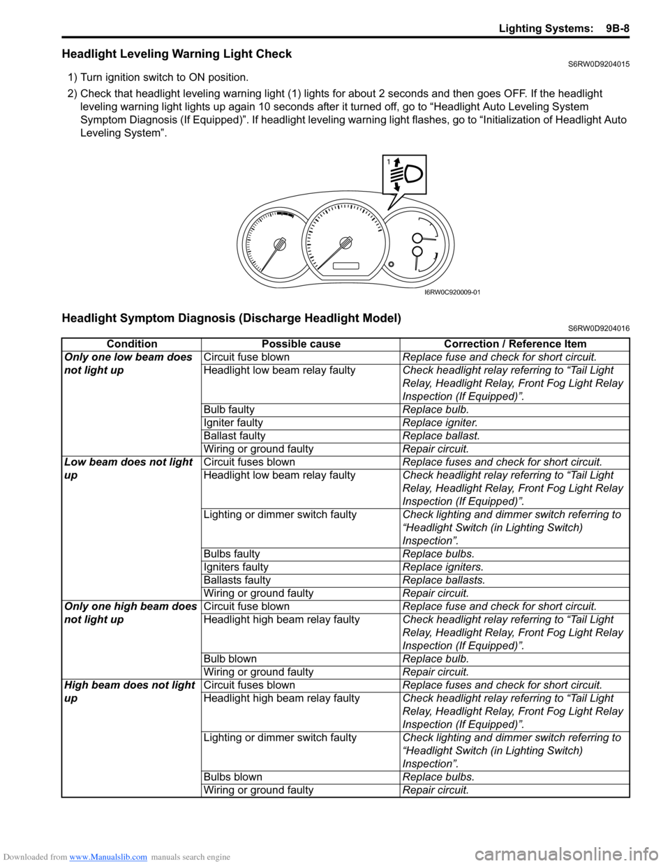
2) Check that headlight leveling warning light (1) lights for about 2 seconds and then goes OFF. If the headlight
leveling warning light lights up again 10 seconds after it turned off, go to “Headlight Auto Leveling System
Symptom Diagnosis (If Equipped)”. If headlight leveling warning light flashes, go to “Initialization of Headlight Auto
Leveling System”.
Headlight Symptom Diagnosis (Discharge Headlight Model)S6RW0D9204016
1
I6RW0C920009-01
Condition Possible cause Correction / Reference Item
Only one low beam does
not light upCircuit fuse blownReplace fuse and check for short circuit.
Headlight low beam relay faultyCheck headlight relay referring to “Tail Light
Relay, Headlight Relay, Front Fog Light Relay
Inspection (If Equipped)”.
Bulb faultyReplace bulb.
Igniter faultyReplace igniter.
Ballast faultyReplace ballast.
Wiring or ground faultyRepair circuit.
Low beam does not light
upCircuit fuses blownReplace fuses and check for short circuit.
Headlight low beam relay faultyCheck headlight relay referring to “Tail Light
Relay, Headlight Relay, Front Fog Light Relay
Inspection (If Equipped)”.
Lighting or dimmer switch faultyCheck lighting and dimmer switch referring to
“Headlight Switch (in Lighting Switch)
Inspection”.
Bulbs faultyReplace bulbs.
Igniters faultyReplace igniters.
Ballasts faultyReplace ballasts.
Wiring or ground faultyRepair circuit.
Only one high beam does
not light upCircuit fuse blownReplace fuse and check for short circuit.
Headlight high beam relay faultyCheck headlight relay referring to “Tail Light
Relay, Headlight Relay, Front Fog Light Relay
Inspection (If Equipped)”.
Bulb blownReplace bulb.
Wiring or ground faultyRepair circuit.
High beam does not light
upCircuit fuses blownReplace fuses and check for short circuit.
Headlight high beam relay faultyCheck headlight relay referring to “Tail Light
Relay, Headlight Relay, Front Fog Light Relay
Inspection (If Equipped)”.
Lighting or dimmer switch faultyCheck lighting and dimmer switch referring to
“Headlight Switch (in Lighting Switch)
Inspection”.
Bulbs blownReplace bulbs.
Wiring or ground faultyRepair circuit.
Page 1360 of 1556
Downloaded from www.Manualslib.com manuals search engine 9C-8 Instrumentation / Driver Info. / Horn:
Brake and Parking Brake Warning Light Symptom DiagnosisS6RW0D9304007
Seat Belt Reminder Light Symptom DiagnosisS6RW0D9304008
A/T Shift Position Indicator Symptom Diagnosis (A/T Model)S6RW0D9304009
Condition Possible cause Correction / Reference Item
Brake warning light does
not light up when brake
fluid level is low or
parking brake is pulled up
or for 5 seconds after
turning ON ignition switchCircuit fuse blownReplace fuse and check for short circuit.
Brake fluid level switch faultyCheck brake fluid level switch referring to
“Brake Fluid Level Switch Inspection”.
Parking brake switch faultyCheck parking brake switch referring to
“Parking Brake Switch Inspection”.
ABS system faultyRefer to “ABS Check in Section 4E”.
Wiring or grounding faultyRepair circuit.
Combination meter faultyReplace combination meter.
BCM faultyReplace after making sure that none of above
parts is faulty.
Brake warning light stays
ONBrake fluid level switch faultyCheck brake fluid level switch referring to
“Brake Fluid Level Switch Inspection”.
Parking brake switch faultyCheck parking brake switch referring to
“Parking Brake Switch Inspection”.
EBD system faultyRefer to “EBD Warning Light (Brake Warning
Light) Check in Section 4E”.
Wiring or grounding faultyRepair circuit.
Combination meter faultyReplace combination meter.
BCM faultyReplace after making sure that none of above
parts is faulty.
Condition Possible cause Correction / Reference Item
Seat belt reminder light
does not light upCircuit fuse blownReplace fuse and check for short circuit.
Seat belt switch faultyCheck seat belt switch referring to “Front Seat
Belt Inspection in Section 8A”.
Wiring or grounding faultyRepair circuit.
Combination meter faultyReplace combination meter.
BCM faultyReplace after making sure that none of above
parts is faulty.
Seat belt reminder light
stays ONSeat belt switch faultyCheck seat belt switch referring to “Front Seat
Belt Inspection in Section 8A”.
Wiring or grounding faultyRepair circuit.
Combination meter faultyReplace combination meter.
BCM faultyReplace after making sure that none of above
parts is faulty.
Condition Possible cause Correction / Reference Item
All A/T shift position
indicator does not light upCircuit fuse blownReplace fuse and check for short circuit.
Transmission range sensor (shift switch)
faultyCheck transmission range sensor referring to
“Transmission Range Sensor Inspection and
Adjustment in Section 5A”.
Wiring or ground faultyRepair circuit.
Combination meter faultyReplace combination meter.
TCM faultyReplace after making sure that none of above
parts is faulty.
Page 1409 of 1556
Downloaded from www.Manualslib.com manuals search engine Glass / Windows / Mirrors: 9E-24
Power Window Main Switch Initialization
(Pinching Prevention Function Model)
S6RW0D9506030
CAUTION!
• After replacing or disconnecting the driver
side door window regulator (motor), power
window main switch, battery or fuse, be
sure to execute initial setting (to have door
glass completely closed position learned).
If initial setting is not executed, correct
automatic operation (including pinching
prevention operation) would not be
available.
• Make sure that no foreign matter is
pinched while executing initial setting.
1) Open driver side door glass fully.
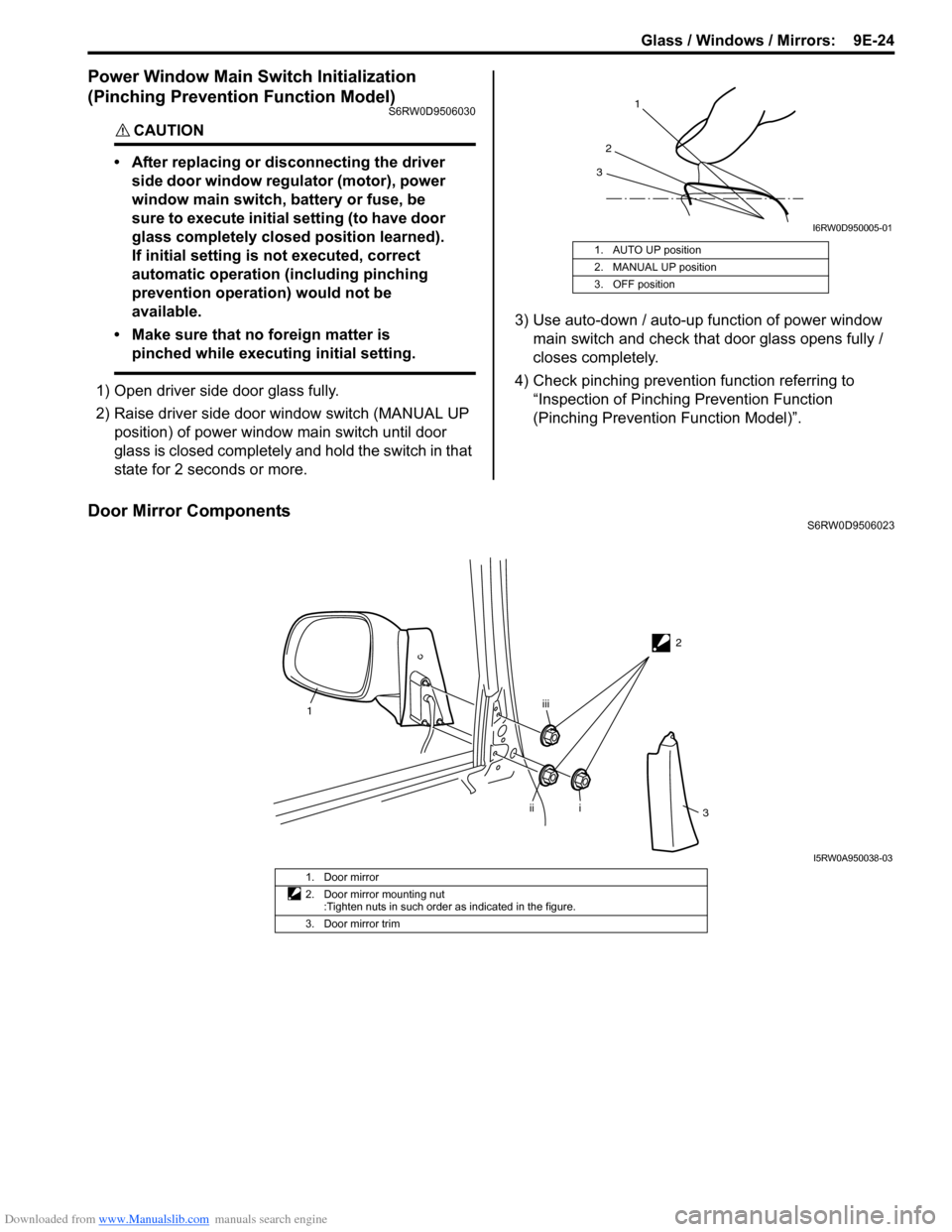
2) Raise driver side door window switch (MANUAL UP
position) of power window main switch until door
glass is closed completely and hold the switch in that
state for 2 seconds or more.3) Use auto-down / auto-up function of power window
main switch and check that door glass opens fully /
closes completely.
4) Check pinching prevention function referring to
“Inspection of Pinching Prevention Function
(Pinching Prevention Function Model)”.
Door Mirror ComponentsS6RW0D9506023 1. AUTO UP position
2. MANUAL UP position
3. OFF position
1
2
3
I6RW0D950005-01
2
1
i
iiiii
3
I5RW0A950038-03
1. Door mirror
2. Door mirror mounting nut
:Tighten nuts in such order as indicated in the figure.
3. Door mirror trim