2006 SUZUKI SX4 section 9
[x] Cancel search: section 9Page 1025 of 1556
Downloaded from www.Manualslib.com manuals search engine Air Conditioning System: Automatic Type 7B-85
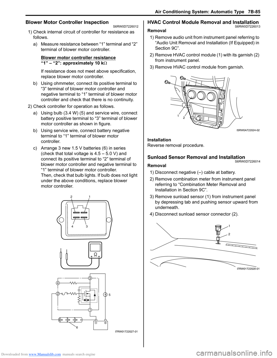
Blower Motor Controller InspectionS6RW0D7226012
1) Check internal circuit of controller for resistance as
follows.
a) Measure resistance between “1” terminal and “2”
terminal of blower motor controller.
Blower motor controller resistance
“1” – “2”: approximately 10 kΩ
If resistance does not meet above specification,
replace blower motor controller.
b) Using ohmmeter, connect its positive terminal to
“3” terminal of blower motor controller and
negative terminal to “1” terminal of blower motor
controller and check that there is no continuity.
2) Check controller for operation as follows.
a) Using bulb (3.4 W) (5) and service wire, connect
battery positive terminal to “3” terminal of blower
motor controller as shown in figure.
b) Using service wire, connect battery negative
terminal to “1” terminal of blower motor
controller.
c) Arrange 3 new 1.5 V batteries (6) in series
(check that total voltage is 4.5 – 5.0 V) and
connect its positive terminal to “2” terminal of
blower motor controller and negative terminal to
“1” terminal of blower motor controller.
Then, check that bulb lights. If bulb does not light
under the above conditions, replace blower
motor controller.
HVAC Control Module Removal and InstallationS6RW0D7226013
Removal
1) Remove audio unit from instrument panel referring to
“Audio Unit Removal and Installation (If Equipped) in
Section 9C”.
2) Remove HVAC control module (1) with its garnish (2)
from instrument panel.
3) Remove HVAC control module from garnish.
Installation
Reverse removal procedure.
Sunload Sensor Removal and InstallationS6RW0D7226014
Removal
1) Disconnect negative (–) cable at battery.
2) Remove combination meter from instrument panel
referring to “Combination Meter Removal and
Installation in Section 9C”.
3) Remove sunload sensor (1) from instrument panel
by depressing tab and pushing sensor upward from
underneath.
4) Disconnect sunload sensor connector (2).
21
43
3
1 2 4
5
6I7RW01722027-01
12
I5RW0A722024-02
1
2
I7RW01722028-01
Page 1026 of 1556
Downloaded from www.Manualslib.com manuals search engine 7B-86 Air Conditioning System: Automatic Type
Installation
Reverse removal procedure noting the following
instructions.
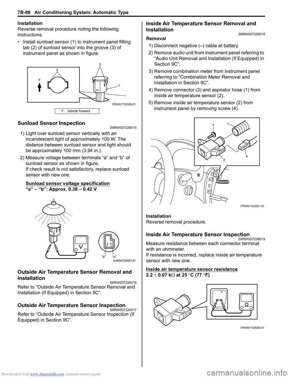
• Install sunload sensor (1) to instrument panel fitting
tab (2) of sunload sensor into the groove (3) of
instrument panel as shown in figure.
Sunload Sensor InspectionS6RW0D7226015
1) Light over sunload sensor vertically with an
incandescent light of approximately 100 W. The
distance between sunload sensor and light should
be approximately 100 mm (3.94 in.).
2) Measure voltage between terminals “a” and “b” of
sunload sensor as shown in figure.
If check result is not satisfactory, replace sunload
sensor with new one.
Sunload sensor voltage specification
“a” – “b”: Approx. 0.38 – 0.42 V
Outside Air Temperature Sensor Removal and
Installation
S6RW0D7226016
Refer to “Outside Air Temperature Sensor Removal and
Installation (If Equipped) in Section 9C”.
Outside Air Temperature Sensor InspectionS6RW0D7226017
Refer to “Outside Air Temperature Sensor Inspection (If
Equipped) in Section 9C”.
Inside Air Temperature Sensor Removal and
Installation
S6RW0D7226018
Removal
1) Disconnect negative (–) cable at battery.
2) Remove audio unit from instrument panel referring to
“Audio Unit Removal and Installation (If Equipped) in
Section 9C”.
3) Remove combination meter from instrument panel
referring to “Combination Meter Removal and
Installation in Section 9C”.
4) Remove connector (3) and aspirator hose (1) from
inside air temperature sensor (2).
5) Remove inside air temperature sensor (2) from
instrument panel by removing screw (4).
Installation
Reverse removal procedure.
Inside Air Temperature Sensor InspectionS6RW0D7226019
Measure resistance between each connector terminal
with an ohmmeter.
If resistance is incorrect, replace inside air temperature
sensor with new one.
Inside air temperature sensor resistance
2.2 ± 0.07 kΩ at 25 °C (77 °F)
F: Vehicle forward
2
F
1
3
I7RW01722029-01
“b” “a”I5JB0A720053-01
1
23 4
I7RW01722031-01
I7RW01722030-01
Page 1029 of 1556
Downloaded from www.Manualslib.com manuals search engine Table of Contents 8- i
8
Section 8
CONTENTS
Restraint
Precautions ................................................. 8-1
Precautions............................................................. 8-1
Precautions on Restraint ....................................... 8-1
Seat Belts ................................................. 8A-1
Precautions........................................................... 8A-1
Precautions on Service and Diagnosis of Seat
Belt .................................................................... 8A-1
General Description ............................................. 8A-2
Seat Belt Construction ........................................ 8A-2
Diagnostic Information and Procedures ............ 8A-3
Repair and Inspection Required after
Accident ............................................................ 8A-3
Repair Instructions .............................................. 8A-4
Front Seat Belt Components ............................... 8A-4
Front Seat Belt Removal and Installation ............ 8A-5
Front Seat Belt Inspection................................... 8A-6
Rear Seat Belt Components ............................... 8A-7
Rear Seat Belt Removal and Installation ............ 8A-8
Rear Seat Belt Inspection ................................... 8A-8
Specifications....................................................... 8A-8
Tightening Torque Specifications ........................ 8A-8
Air Bag System ........................................ 8B-1
Precautions........................................................... 8B-1
Precautions on Service and Diagnosis of Air
Bag System....................................................... 8B-1
Precautions on Handling and Storage of Air
Bag System Components ................................. 8B-1
Precautions on Disposal of Air Bag and Seat
Belt Pretensioner .............................................. 8B-5
General Description ............................................. 8B-5
Air Bag System Construction .............................. 8B-5
Air Bag System Block Diagram ........................... 8B-6
Air Bag System Input / Output Table .................. 8B-7
Schematic and Routing Diagram ........................ 8B-8
Air Bag System Wiring Circuit Diagram .............. 8B-8
Component Location ......................................... 8B-11
Air Bag System Components, Wiring and
Connectors Location ....................................... 8B-11
Diagnostic Information and Procedures .......... 8B-12
Air Bag Diagnostic System Check .................... 8B-12
Air Bag Diagnostic System Check Flow ............ 8B-13
DTC Table ......................................................... 8B-14DTC Check........................................................ 8B-18
DTC Clearance ................................................. 8B-18
Scan Tool Data ................................................. 8B-18
“AIR BAG” Warning Light Comes ON Steady ... 8B-19
“AIR BAG” Warning Light Does Not Come ON .. 8B-22
Serial Data Link Circuit Check .......................... 8B-23
DTC B1013: SDM Internal Failure .................... 8B-25
DTC B1014: “AIR BAG” Warning Light Circuit .. 8B-26
DTC B1016: Power Supply Voltage too High.... 8B-26
DTC B1017: Power Supply Voltage too Low .... 8B-27
DTC B1021: Front Air Bag Deployment
Record............................................................. 8B-28
DTC B1024 / B1025: Side Air-Bag
Deployment Record ........................................ 8B-29
DTC B1026: Seat Belt Pretensioner
Activation Record ............................................ 8B-29
DTC B1027: Number of Deployment Times
Exceeded Limit................................................ 8B-30
DTC B1031: Driver Air Bag Circuit High
Resistance ...................................................... 8B-31
DTC B1032: Driver Air Bag Circuit Low
Resistance ...................................................... 8B-33
DTC B1033: Driver Air Bag Circuit Shorted to
Ground ............................................................ 8B-35
DTC B1034: Driver Air Bag Circuit Shorted to
Power Supply .................................................. 8B-37
DTC B1041: Passenger Air Bag Circuit High
Resistance ...................................................... 8B-40
DTC B1042: Passenger Air Bag Circuit Low
Resistance ...................................................... 8B-43
DTC B1043: Passenger Air Bag Circuit
Shorted to Ground........................................... 8B-45
DTC B1044: Passenger Air Bag Circuit
Shorted to Power Supply ................................ 8B-46
DTC B1051 / B1055: Seat Belt Pretensioner
Circuit High Resistance ................................... 8B-48
DTC B1052 / B1056: Seat Belt Pretensioner
Circuit Low Resistance.................................... 8B-51
DTC B1053 / B1057: Seat Belt Pretensioner
Shorted to Ground........................................... 8B-52
DTC B1054 / B1058: Seat Belt Pretensioner
Circuit Shorted to Power Supply ..................... 8B-54
DTC B1061 / B1065: Side-Air Bag Circuit
High Resistance .............................................. 8B-55
Page 1031 of 1556
Downloaded from www.Manualslib.com manuals search engine Precautions: 8-1
Restraint
Precautions
Precautions
Precautions on RestraintS6RW0D8000001
Air Bag Warning
Refer to “Air Bag System Service Warning in Section 00”.
Fastener Caution
Refer to “Fastener Caution in Section 00”.
Precautions on Service and Diagnosis of Seat Belt
Refer to “Precautions on Service and Diagnosis of Seat Belt in Section 8A”.
Precautions on Service and Diagnosis of Air Bag System
Refer to “Precautions on Service and Diagnosis of Air Bag System in Section 8B”.
Precautions on Handling and Storage of Air Bag Components
Refer to “Precautions on Handling and Storage of Air Bag System Components in Section 8B”.
Precautions on Disposal of Air Bag and Seat Belt Pretensioner
Refer to “Precautions on Disposal of Air Bag and Seat Belt Pretensioner in Section 8B”.
Page 1034 of 1556
Downloaded from www.Manualslib.com manuals search engine 8A-3 Seat Belts:
Seat Belt with ELR
The seat belt with emergency locking retractor (ELR) is
designed so that it locks immediately (to prevent the
webbing from being pulled out of the retractor any
further) when any of the following items is detected as
exceeding each set value;
• Speed at which the webbing is pulled out of the
retractor.
• Acceleration or deceleration of the vehicle speed.
• Inclination.
Seat Belt with A-ELR
The automatic and emergency locking retractor (A-ELR)
works as an Emergency Locking Retractor (ELR) till its
webbing is pulled all the way out and then on as an
Automatic Locking Retractor (ALR) till it is retracted fully.
ALR: Automatically locks when the webbing is pulled out
from the retractor and allowed to retract even a little.
Then the webbing can not be pulled out any further,
unless it is wound all the way back into the retractor,
which releases the lock and allows the webbing to be
pulled out.
Seat Belt with ELR and Pretensioner
The seat belt with ELR and a pretensioner has a
pretensioner mechanism which operates in linkage with
the air bag in addition to the described ELR.The pretensioner is incorporated in retractor and
controlled by SDM as one of air bag system
components. It will be activated at the same time as the
driver and passenger air bag module when an impact at
the front of vehicle exceeds the specified value.
When servicing seat belt (retractor) with pretensioner, be
sure to observe all WARNINGS and CAUTIONS and
“Precautions on Service and Diagnosis of Air Bag
System in Section 8B”.
CAUTION!
Do not reuse the seat belt pretensioner
(retractor) that has activated. Replace it with
a new seat belt and buckle together as a set.
For checking procedure of its activation,
refer to “Repair and Inspection Required after
Accident in Section 8B”.
Seat Belt Remainder
When driver’s seat belt is unfastened (under the
following conditions), seat belt reminder light inform that
driver’s seat belt is unfastened. Seat belt reminder light
located in combination meter located inside BCM
operate as follows:
• Seat belt reminder light comes on when driver’s seat
belt is unfastened while ignition key switch is at ON
position.
Diagnostic Information and Procedures
Repair and Inspection Required after AccidentS6RW0D8104001
After an accident, whether the seat belt pretensioner has been activated or not, be sure to perform checks and repairs
described on “Repair and Inspection Required after Accident in Section 8B”.
Page 1036 of 1556
Downloaded from www.Manualslib.com manuals search engine 8A-5 Seat Belts:
Front Seat Belt Removal and InstallationS6RW0D8106002
WARNING!
• Never attempt to disassemble or repair the
retractor (seat belt pretensioner). If any
abnormality is found, be sure to replace it
with new one as an assembly.
• Be sure to read “Precautions on Service
and Diagnosis of Seat Belt” before starting
to work and observe every precaution
during work. Neglecting them may result in
personal injury or unactivation of the seat
belt pretensioner when necessary.
Removal
1) Disconnect negative (–) cable at battery.
2) Disable air bag system. Refer to “Disabling Air Bag
System in Section 8B”.
3) Remove center pillar lower trim.
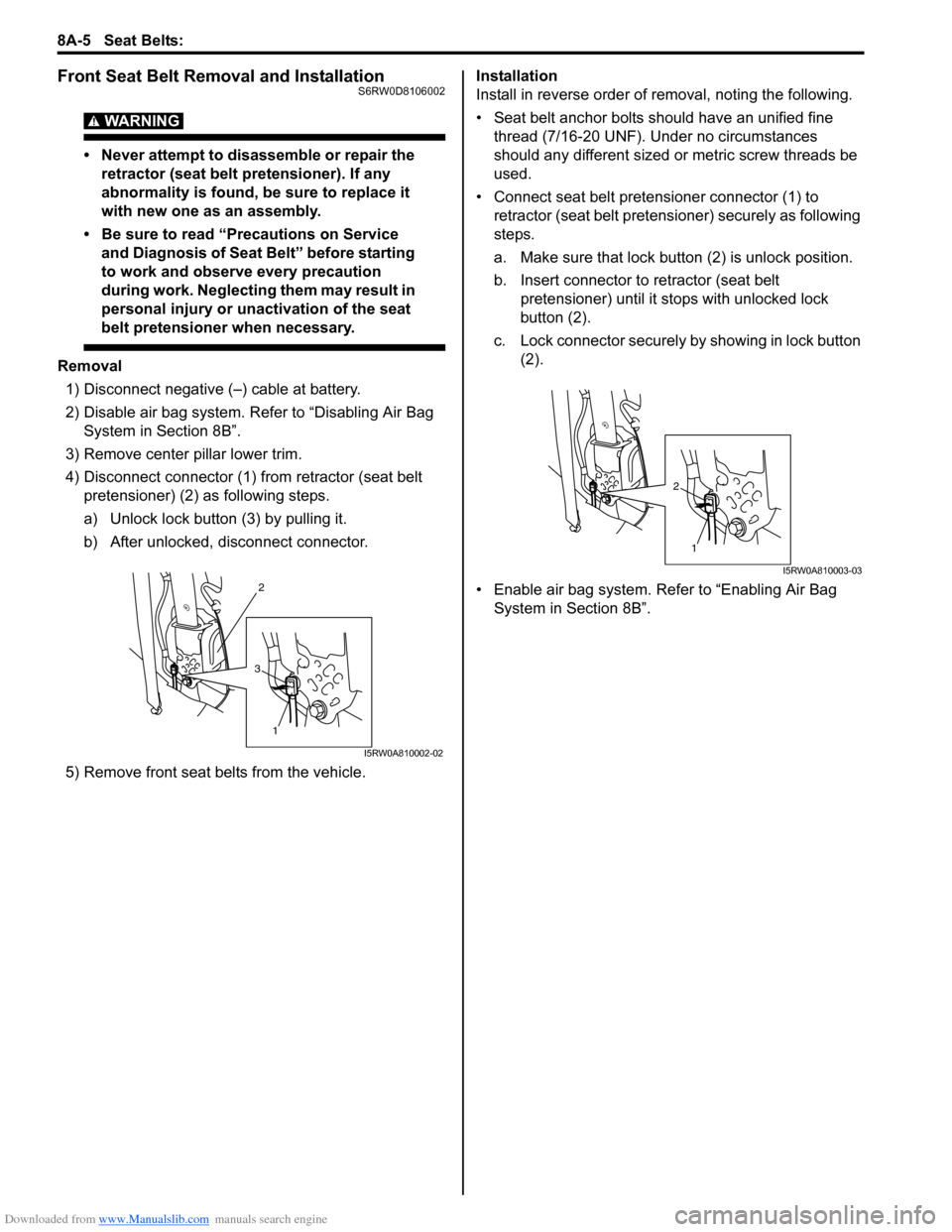
4) Disconnect connector (1) from retractor (seat belt
pretensioner) (2) as following steps.
a) Unlock lock button (3) by pulling it.
b) After unlocked, disconnect connector.
5) Remove front seat belts from the vehicle.Installation
Install in reverse order of removal, noting the following.
• Seat belt anchor bolts should have an unified fine
thread (7/16-20 UNF). Under no circumstances
should any different sized or metric screw threads be
used.
• Connect seat belt pretensioner connector (1) to
retractor (seat belt pretensioner) securely as following
steps.
a. Make sure that lock button (2) is unlock position.
b. Insert connector to retractor (seat belt
pretensioner) until it stops with unlocked lock
button (2).
c. Lock connector securely by showing in lock button
(2).
• Enable air bag system. Refer to “Enabling Air Bag
System in Section 8B”.
2
1
3
I5RW0A810002-02
1
2
I5RW0A810003-03
Page 1039 of 1556
Downloaded from www.Manualslib.com manuals search engine Seat Belts: 8A-8
Rear Seat Belt Removal and InstallationS6RW0D8106005
WARNING!
Be sure to read “Precautions on Service and
Diagnosis of Seat Belt” before starting to
work and observe every precaution during
work.
Removal
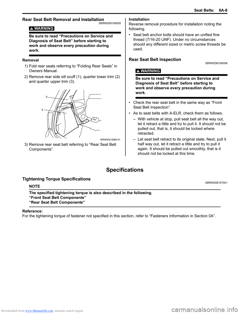
1) Fold rear seats referring to “Folding Rear Seats” in
Owners Manual.
2) Remove rear side sill scuff (1), quarter lower trim (2)
and quarter upper trim (3).
3) Remove rear seat belt referring to “Rear Seat Belt
Components”.Installation
Reverse removal procedure for installation noting the
following.
• Seat belt anchor bolts should have an unified fine
thread (7/16-20 UNF). Under no circumstances
should any different sized or metric screw threads be
used.Rear Seat Belt InspectionS6RW0D8106006
WARNING!
Be sure to read “Precautions on Service and
Diagnosis of Seat Belt” before starting to
work and observe every precaution during
work.
• Check the rear seat belt in the same way as “Front
Seat Belt Inspection”.
• As to seat belts with A-ELR, check them as follows.
– With vehicle at stop, pull seat belt all the way out,
let it retract a little and try to pull it. It should not be
pulled out, that is, it should be locked where
retracted.
– Let seat belt retract to its original state. Next, pull it
half way out, let it retract a little and try to pull it
again. It should be pulled out smoothly, that is it
should not be locked at this time.
Specifications
Tightening Torque SpecificationsS6RW0D8107001
NOTE
The specified tightening torque is also described in the following.
“Front Seat Belt Components”
“Rear Seat Belt Components”
Reference:
For the tightening torque of fastener not specified in this section, refer to “Fasteners Information in Section 0A”.
1 23I5RW0A810005-01
Page 1040 of 1556
Downloaded from www.Manualslib.com manuals search engine 8B-1 Air Bag System:
Restraint
Air Bag System
Precautions
Precautions on Service and Diagnosis of Air
Bag System
S6RW0D8200004
WARNING!
• If the air bag system and another vehicle
system both need repair, SUZUKI
recommends that the air bag system be
repaired first, to help avoid unintended air
bag system activation.
• Do not modify the steering wheel,
dashboard, both front seat or any other on
or around air bag system components.
Modifications can adversely affect air bag
system performance and lead to injury.
• Be sure to follow the procedures described
in this section. Failure to follow
procedures could result in possible air bag
system activation, personal injury or
unneeded air bag system repairs.
• WARNING / CAUTION labels are attached on each
part of air bag system components (SDM, air bag
(inflator) modules and seat belt pretensioners). Be
sure to follow the instructions.
• Many of service procedures require disconnection of
“A/B” fuse and air bag (inflator) module(s) (driver
module, passenger module, side modules and curtain
modules) from initiator circuit to avoid an accidental
deployment.
• Do not apply power to the air bag system unless all
components are connected or a diagnostic flow
requests it, as this will set a DTC.
• The “Air Bag Diagnostic System Check” must be the
starting point of any air bag diagnostics. The “Air Bag
Diagnostic System Check” will verify proper “AIR
BAG” warning light operation and will lead you to the
correct flow to diagnose any air bag malfunctions.
Bypassing these procedures may result in extended
diagnostic time, incorrect diagnosis, and incorrect
parts replacements.
• Never use air bag component parts from another
vehicle.
• If the vehicle will be exposed to temperatures over 93
°C (200 °F) (for example, during a paint baking
process), remove the air bag system components
beforehand to avoid component damage or
unintended system activation.• When handling the air bag (inflator) modules (driver
module, passenger module, side modules and curtain
modules), seat belt pretensioners (driver module and
passenger module), SDM, forward impact-sensor or
side impact-sensor be careful not to drop it or apply
an impact to it. If an excessive impact was applied
(e.g., SDM, forward impact-sensor are dropped, air
bag (inflator) module is dropped from a height of 90
cm (3 ft) or more, seat belt pretensioner (retractor
assembly) is dropped from a height of 30 cm (1 ft) or
more), never attempt disassembly or repair but
replace it with a new one.
• When using electric welding, be sure to disconnect air
bag (inflator) module connectors (driver module,
passenger module, side modules and curtain
modules) and seat belt pretensioner connectors
(driver module and passenger module) respectively.
• When applying paint around the air bag system
related parts, use care so that the harness or
connector will not be exposed to the paint mist.
• Never expose air bag system component parts
directly to hot air (drying or baking the vehicle after
painting) or flames.
WARNING!
When performing service on or around air
bag system components or air bag wiring,
follow the procedures listed in “Disabling Air
Bag System” to temporarily disable the air
bag system.
Failure to follow procedures could result in
possible air bag system activation, personal
injury or unneeded air bag system repairs.
Precautions on Handling and Storage of Air Bag
System Components
S6RW0D8200002
SDM
WARNING!
Never power up air bag system when SDM is
not rigidly attached to the vehicle. Otherwise,
personal injury may result.
CAUTION!
After detecting one time of such collision as
to meet deployment conditions, SDM must
not be used. Refer to “Air Bag Diagnostic
System Check” when checking SDM.