2006 SUZUKI SX4 engine ecu
[x] Cancel search: engine ecuPage 278 of 1556

Downloaded from www.Manualslib.com manuals search engine 1C-10 Engine Electrical Devices:
Performance check
1) Remove metal particles on end face of CMP sensor,
if any.
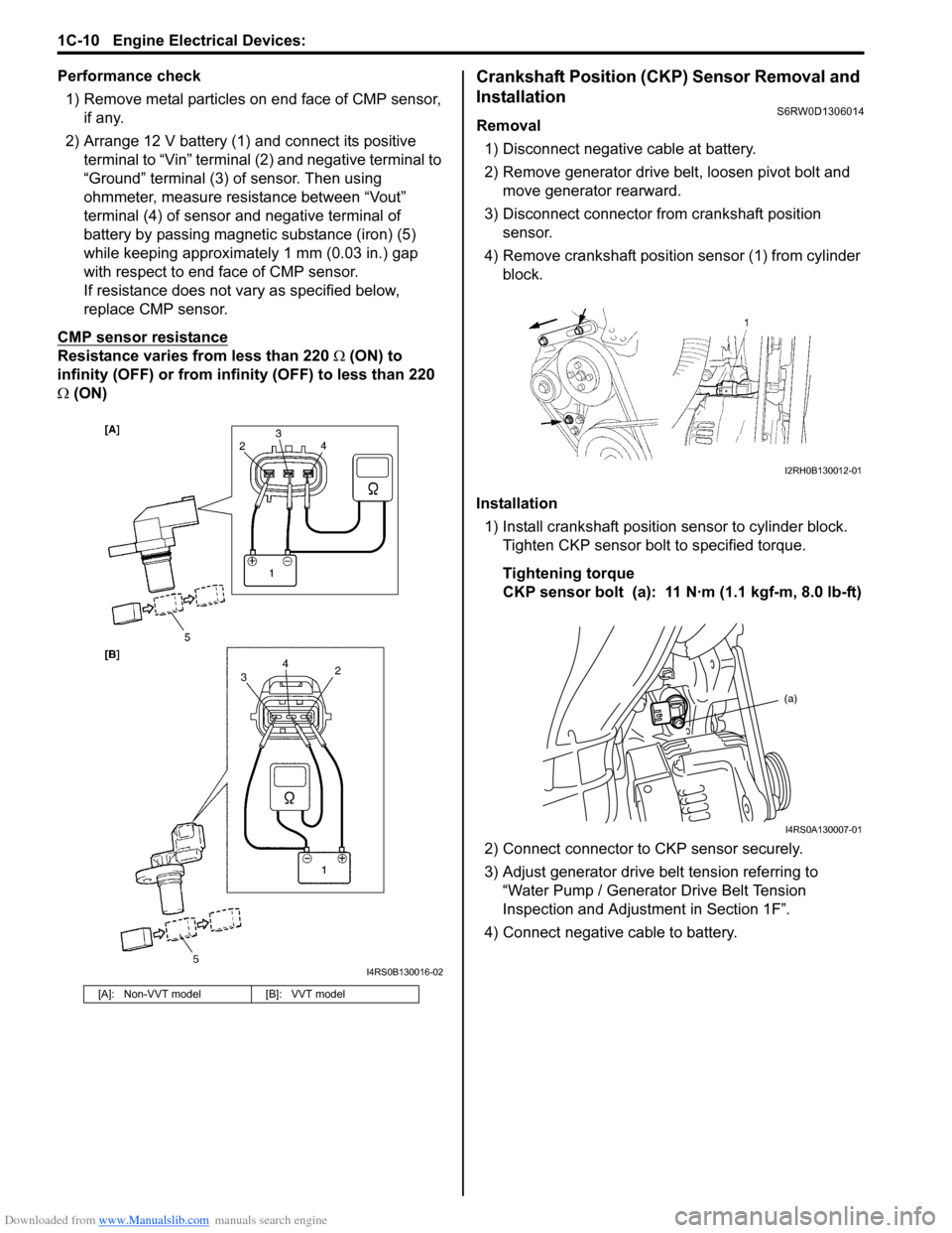
2) Arrange 12 V battery (1) and connect its positive
terminal to “Vin” terminal (2) and negative terminal to
“Ground” terminal (3) of sensor. Then using
ohmmeter, measure resistance between “Vout”
terminal (4) of sensor and negative terminal of
battery by passing magnetic substance (iron) (5)
while keeping approximately 1 mm (0.03 in.) gap
with respect to end face of CMP sensor.
If resistance does not vary as specified below,
replace CMP sensor.
CMP sensor resistance
Resistance varies from less than 220 Ω (ON) to
infinity (OFF) or from infinity (OFF) to less than 220
Ω (ON)
Crankshaft Position (CKP) Sensor Removal and
Installation
S6RW0D1306014
Removal
1) Disconnect negative cable at battery.
2) Remove generator drive belt, loosen pivot bolt and
move generator rearward.
3) Disconnect connector from crankshaft position
sensor.
4) Remove crankshaft position sensor (1) from cylinder
block.
Installation
1) Install crankshaft position sensor to cylinder block.
Tighten CKP sensor bolt to specified torque.
Tightening torque
CKP sensor bolt (a): 11 N·m (1.1 kgf-m, 8.0 lb-ft)
2) Connect connector to CKP sensor securely.
3) Adjust generator drive belt tension referring to
“Water Pump / Generator Drive Belt Tension
Inspection and Adjustment in Section 1F”.
4) Connect negative cable to battery.
[A]: Non-VVT model [B]: VVT model
I4RS0B130016-02
I2RH0B130012-01
(a)
I4RS0A130007-01
Page 281 of 1556

Downloaded from www.Manualslib.com manuals search engine Engine Electrical Devices: 1C-13
Mass Air Flow (MAF) and Intake Air
Temperature (IAT) Sensor Removal and
Installation
S6RW0D1306019
CAUTION!
• Do not disassemble MAF and IAT sensor.
• Do not expose MAF and IAT sensor to any
shock.
• Do not clean MAF and IAT sensor.
• If MAF and IAT sensor has been dropped, it
should be replaced.
• Do not blow compressed air by using air
gun or the like.
• Do not put finger or any other object into
MAF and IAT sensor. Malfunction may
occur.
Removal
1) Disconnect negative cable at battery.
2) Disconnect MAF and IAT sensor connector.
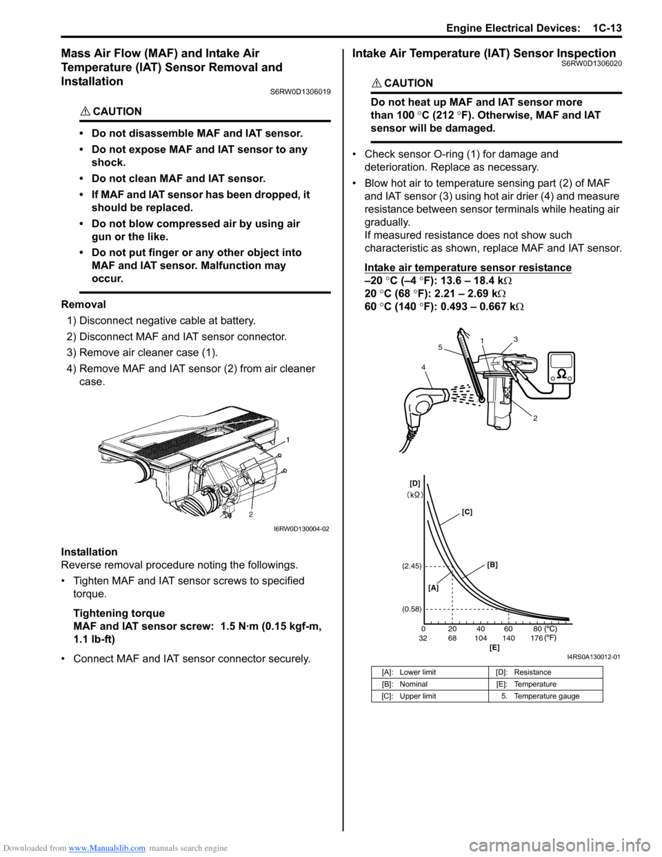
3) Remove air cleaner case (1).
4) Remove MAF and IAT sensor (2) from air cleaner
case.
Installation
Reverse removal procedure noting the followings.
• Tighten MAF and IAT sensor screws to specified
torque.
Tightening torque
MAF and IAT sensor screw: 1.5 N·m (0.15 kgf-m,
1.1 lb-ft)
• Connect MAF and IAT sensor connector securely.
Intake Air Temperature (IAT) Sensor InspectionS6RW0D1306020
CAUTION!
Do not heat up MAF and IAT sensor more
than 100 °C (212 °F). Otherwise, MAF and IAT
sensor will be damaged.
• Check sensor O-ring (1) for damage and
deterioration. Replace as necessary.
• Blow hot air to temperature sensing part (2) of MAF
and IAT sensor (3) using hot air drier (4) and measure
resistance between sensor terminals while heating air
gradually.
If measured resistance does not show such
characteristic as shown, replace MAF and IAT sensor.
Intake air temperature sensor resistance
–20 °C (–4 °F): 13.6 – 18.4 kΩ
20 °C (68 °F): 2.21 – 2.69 kΩ
60 °C (140 °F): 0.493 – 0.667 kΩ
I6RW0D130004-02
[A]: Lower limit [D]: Resistance
[B]: Nominal [E]: Temperature
[C]: Upper limit 5. Temperature gauge
20 0
68 32 104 140 17640 60 80 (2.45)
(0.58)
1
2 3
45
[A][B]
[E] [C] [D]
I4RS0A130012-01
Page 286 of 1556

Downloaded from www.Manualslib.com manuals search engine 1D-4 Engine Mechanical:
Oil Control Valve
The oil control valve switches and adjusts the hydraulic
pressure applied to the cam timing sprocket by moving
the spool valve (1) according to the duty pulse signals
output from the ECM. By this operation, the intake valve
timing is varied continuously. Signals output from the
ECM are the duty pulse of about 240 Hz.
Cam Timing Sprocket
The cam timing sprocket is equipped with the chambers
for timing advancing (2) and retarding (3) which are
separated by the rotor (5). The rotor rotates receiving the
hydraulic pressure applied to both the chambers. The
sprocket (1) is installed on the housing (4) and the rotor
is secured on the intake camshaft by fastening the bolts.
Therefore, the actuation of the rotor makes the phase
difference between the sprocket and intake camshaft.
Timing Advancing
When the duty ratio of the signal output from the ECM is
heavy, the spool valve (4) of the oil control valve moves
to the left (opposite direction against the coil (5)). By this
spool valve movement, the pressurized oil (1) is led into
the chambers for timing advancing and the oil in the
chambers for timing retarding is drained. This operations
actuate the rotor (3) and result in the advanced timing of
the intake valve.Timing Holding
When the duty ratio of the signal output from the ECM
shows that of holding, the spool valve of the oil control
valve is located at hold position. Because this condition
generates no oil pressure changes in both chambers,
the rotor is fixed at a target position.
Timing Retarding
When the duty ratio of the signal output from the ECM is
light, the spool valve of the oil control valve moves to the
right (head for the coil). By this spool valve movement,
the pressurized oil is led into the chambers for timing
retarding and the oil in the chambers for timing
advancing is drained. This operations actuate the rotor
and result in the retarded timing of the intake valve.
6. Seal
2. Drain
1
I5RW0C140034-01
12
3 4
5
6
I3RH0B140004-01
1
2
5
4
3
I5RW0C140035-01
I5RW0C140036-01
I5RW0C140037-01
Page 294 of 1556

Downloaded from www.Manualslib.com manuals search engine 1D-12 Engine Mechanical:
Installation
1) Install new spark plug hole gaskets (1) and new
cylinder head cover gasket (2) to cylinder head cover
(3) as shown in figure.
2) Remove oil, old sealant, and dust from sealing
surfaces on cylinder head and cover. After cleaning,
apply sealant “A” to the following point.
• Cylinder head cover gasket (1) sealing surface
area (2) as shown.
“A”: Water tight sealant 99000–31250
(SUZUKI Bond No.1207F)• Timing chain cover (1) and cylinder head (2)
mating surface as shown.
“A”: Water tight sealant 99000–31250
(SUZUKI Bond No.1207F)
3) Install cylinder head cover to cylinder head.
NOTE
When installing cylinder head cover, use care
so that cylinder head cover gasket or spark
plug hole gaskets will not get out of place or
fall off.
4) Tightening bolts in numerical order (“1” through “7”)
as shown in figure a little at a time till they are
tightened to specified torque.
Tightening torque
Cylinder head cover bolt (a): Tighten 8 N⋅m (0.8
kgf-m, 6.0 lb-ft) by the specified procedure
5) Connect PCV hose (2) to PCV valve (3).
6) Connect breather hose (4).
7) Install oil level gauge (1).
8) Install ignition coil assemblies to cylinder head cover
referring to “Ignition Coil Assembly (Including Ignitor)
Removal and Installation in Section 1H”.
9) Connect ignition coil couplers and clamp harness
securely.
10) Install cylinder head upper cover.
11) Install air cleaner assembly referring to “Air Cleaner
Assembly Removal and Installation”.
12) Connect negative cable at battery.I6RS0B141005-01
I2RH0B140036-01
I2RH0B140037-01
I3RH0B140016-01
Page 296 of 1556

Downloaded from www.Manualslib.com manuals search engine 1D-14 Engine Mechanical:
Throttle Body On-Vehicle InspectionS6RW0D1406006
Check electric throttle body assembly referring to
“Throttle Valve Operation Check” and “Electric Throttle
Body Assembly Operation Check” under “Electric
Throttle Body Assembly On-Vehicle Inspection in
Section 1C”.
Electric Throttle Body Assembly Removal and
Installation
S6RW0D1406047
CAUTION!
Never disassemble electric throttle body.
Disassembly will spoil its original
performance. If faulty condition is found,
replace it with new one.
Removal
1) Disconnect negative cable at battery.
2) Drain coolant referring to “Cooling System Draining
in Section 1F”.
3) Remove air cleaner assembly referring to “Air
Cleaner Assembly Removal and Installation”.
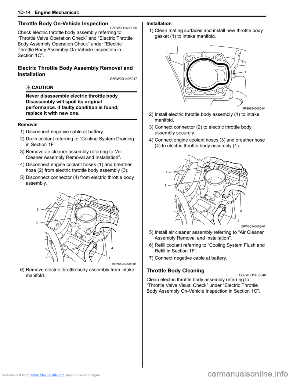
4) Disconnect engine coolant hoses (1) and breather
hose (2) from electric throttle body assembly (3).
5) Disconnect connector (4) from electric throttle body
assembly.
6) Remove electric throttle body assembly from intake
manifold.Installation
1) Clean mating surfaces and install new throttle body
gasket (1) to intake manifold.
2) Install electric throttle body assembly (1) to intake
manifold.
3) Connect connector (2) to electric throttle body
assembly securely.
4) Connect engine coolant hoses (3) and breather hose
(4) to electric throttle body assembly (1).
5) Install air cleaner assembly referring to “Air Cleaner
Assembly Removal and Installation”.
6) Refill coolant referring to “Cooling System Flush and
Refill in Section 1F”.
7) Connect negative cable at battery.
Throttle Body CleaningS6RW0D1406048
Clean electric throttle body assembly referring to
“Throttle Valve Visual Check” under “Electric Throttle
Body Assembly On-Vehicle Inspection in Section 1C”.
2
4
3
1
I5RW0C140006-01
1
I4RS0B140005-01
4
2
1
3
I5RW0C140008-01
Page 306 of 1556

Downloaded from www.Manualslib.com manuals search engine 1D-24 Engine Mechanical:
Installation
1) Clean sealing surface on timing chain cover, cylinder
block and cylinder head.
Remove oil, old sealant and dust from sealing
surface.
2) Install oil seal (1) to timing chain cover, if removed.
NOTE
When installing new oil seal, press fit to
timing chain cover (2) by using special tool
(bearing installer) as shown in figure.
Drive in dimension
“a”: 1.0 mm (0.04 in.)
Special tool
(A): 09913–75810
3) For engine with VVT, install oil control valve to timing
chain cover referring to “Oil Control Valve Removal
and Installation (For Engine with VVT)”.
4) Apply sealant “A” to mating surface of cylinder and
cylinder head and “B” to mating surface of timing
chain cover as shown in figure.
“A”: Water tight sealant 99000–31140 (SUZUKI
Bond No.1207B)
“B”: Sealant 99000–31260 (SUZUKI Bond
No.1217G)
Sealant amount for timing chain cover
Width “a”: 3 mm (0.12 in.)
Height “b”: 2 mm (0.08 in.)5) Apply engine oil to oil seal lip, then install timing
chain cover (1). Tighten bolts and nut to specified
torque.
NOTE
Before installing timing chain cover, check
that pin is securely fitted.
Tightening torque
Timing chain cover bolt (a): 25 N·m (2.5 kgf-m,
18.0 lb-ft)
Timing chain cover nut (b): 25 N·m (2.5 kgf-m,
18.0 lb-ft)
6) Apply engine oil to new O-rings (2) and install them
to cap (3).
7) Install cap (3) to timing chain cover (1).
Tighten bolts to specified torque.
Tightening torque
Cap bolt (c): 25 N·m (2.5 kgf-m, 18.0 lb-ft)
I2RH0B140058-01
I5RW0C140043-01
(a) (b) (c)
1 2 3
I4RS0B140011-02
Page 321 of 1556

Downloaded from www.Manualslib.com manuals search engine Engine Mechanical: 1D-39
Valves and Cylinder Head ComponentsS6RW0D1406025
I4RS0A140015-01
1. Valve cotters 7. Exhaust valve 13. Cylinder head bolt (M8)
: Be sure to tighten cylinder head bolt (M8) after
securing the other cylinder head bolt (M10).
2. Valve spring retainer 8. Valve guide : Tighten 20 N⋅m (2.0 kgf-m, 14.5 lb-ft), 40 N⋅m (4.0 kgf-
m, 29.0 lb-ft), 60° and 60° by the specified procedure.
3. Valve spring 9. Cylinder head bolt (M10)
: Check cylinder head bolt (M10), plastic deformation
tightening bolt, for deformation referring to “Valves and
Cylinder Head Removal and Installation”, if it is reused.: Tighten 25 N⋅m (2.5 kgf-m, 18.0 lb-ft) by the specified
procedure
4. Valve stem seal 10. Cylinder head : Do not reuse.
5. Valve spring seat 11. Cylinder head gasket
: “TOP” mark provided on gasket comes to crankshaft
pulley side, facing up.: Apply engine oil to sliding surface of each part.
6. Intake valve 12. Knock pin
Page 323 of 1556

Downloaded from www.Manualslib.com manuals search engine Engine Mechanical: 1D-41
5) Install cylinder head to cylinder block.
Apply engine oil to new cylinder head bolts and
tighten them gradually as follows.
a) Tighten cylinder head bolts (“1” – “10”) to 20 N⋅m
(2.0 kgf-m, 14.5 lb-ft) according to numerical
order as shown by using a 12 corner socket
wrenches.
b) In the same manner as in Step a), tighten them
to 40 N⋅m (4.0 kgf-m, 29.0 lb-ft).
c) Turn all bolts 60° according to numerical order in
figure.
d) Repeat Step c).
e) Tighten cylinder head bolt (M8) (1) to specified
torque.
NOTE
Be sure to tighten M8 bolt (1) after securing
the other bolts.
Tightening torque
Cylinder head bolt for M8 (a): Tighten 25 N⋅m
(2.5 kgf-m, 18.0 lb-ft) by the specified
procedure
Cylinder head bolt for M10 (b): Tighten 20
N⋅m (2.0 kgf-m, 14.5 lb-ft), 40 N⋅m (4.0 kgf-m,
29.0 lb-ft), 60° and 60° by the specified
procedure
NOTE
• If cylinder head bolts (M10) are reused,
check thread diameters of cylinder head
bolt (1) for deformation according to the
follows and replace them with new ones if
thread diameter difference exceeds limit.
• Measure each thread diameter of cylinder
head bolt (1) at “A” on 83.5 mm (2.81 in.)
from seat side of flange bolt and “B” on
115 mm (4.53 in.) from seat side of flange
bolt by using a micrometer (2).
Then calculate difference in diameters (“A”
– “B”). If it exceeds limit, replace with new
one.
Cylinder head bolt diameter measurement
points
“a”: 83.5 mm (2.81 in.)
“b”: 115 mm (4.53 in.)
Cylinder head bolt diameter difference
(deformation)
Limit (“A” – “B”): 0.1 mm (0.004 in.)
6) Install camshafts, tappet and shim referring to
“Camshaft, Tappet and Shim Removal and
Installation”.
7) Install timing chain referring to “Timing Chain and
Chain Tensioner Removal and Installation”.
8) Install timing chain cover referring to “Timing Chain
Cover Removal and Installation”.
9) Install cylinder head cover referring to “Cylinder
Head Cover Removal and Installation”.
10) Install oil pan referring to “Oil Pan and Oil Pump
Strainer Removal and Installation in Section 1E”.
I5RW0C140030-01
“A”
“a”
“b”“B”
1
12
I2RH0B140092-01