2006 SUZUKI SX4 air condition
[x] Cancel search: air conditionPage 1040 of 1556
Downloaded from www.Manualslib.com manuals search engine 8B-1 Air Bag System:
Restraint
Air Bag System
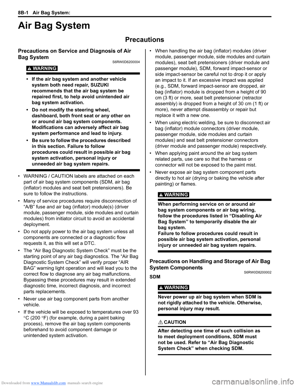
Precautions
Precautions on Service and Diagnosis of Air
Bag System
S6RW0D8200004
WARNING!
• If the air bag system and another vehicle
system both need repair, SUZUKI
recommends that the air bag system be
repaired first, to help avoid unintended air
bag system activation.
• Do not modify the steering wheel,
dashboard, both front seat or any other on
or around air bag system components.
Modifications can adversely affect air bag
system performance and lead to injury.
• Be sure to follow the procedures described
in this section. Failure to follow
procedures could result in possible air bag
system activation, personal injury or
unneeded air bag system repairs.
• WARNING / CAUTION labels are attached on each
part of air bag system components (SDM, air bag
(inflator) modules and seat belt pretensioners). Be
sure to follow the instructions.
• Many of service procedures require disconnection of
“A/B” fuse and air bag (inflator) module(s) (driver
module, passenger module, side modules and curtain
modules) from initiator circuit to avoid an accidental
deployment.
• Do not apply power to the air bag system unless all
components are connected or a diagnostic flow
requests it, as this will set a DTC.
• The “Air Bag Diagnostic System Check” must be the
starting point of any air bag diagnostics. The “Air Bag
Diagnostic System Check” will verify proper “AIR
BAG” warning light operation and will lead you to the
correct flow to diagnose any air bag malfunctions.
Bypassing these procedures may result in extended
diagnostic time, incorrect diagnosis, and incorrect
parts replacements.
• Never use air bag component parts from another
vehicle.
• If the vehicle will be exposed to temperatures over 93
°C (200 °F) (for example, during a paint baking
process), remove the air bag system components
beforehand to avoid component damage or
unintended system activation.• When handling the air bag (inflator) modules (driver
module, passenger module, side modules and curtain
modules), seat belt pretensioners (driver module and
passenger module), SDM, forward impact-sensor or
side impact-sensor be careful not to drop it or apply
an impact to it. If an excessive impact was applied
(e.g., SDM, forward impact-sensor are dropped, air
bag (inflator) module is dropped from a height of 90
cm (3 ft) or more, seat belt pretensioner (retractor
assembly) is dropped from a height of 30 cm (1 ft) or
more), never attempt disassembly or repair but
replace it with a new one.
• When using electric welding, be sure to disconnect air
bag (inflator) module connectors (driver module,
passenger module, side modules and curtain
modules) and seat belt pretensioner connectors
(driver module and passenger module) respectively.
• When applying paint around the air bag system
related parts, use care so that the harness or
connector will not be exposed to the paint mist.
• Never expose air bag system component parts
directly to hot air (drying or baking the vehicle after
painting) or flames.
WARNING!
When performing service on or around air
bag system components or air bag wiring,
follow the procedures listed in “Disabling Air
Bag System” to temporarily disable the air
bag system.
Failure to follow procedures could result in
possible air bag system activation, personal
injury or unneeded air bag system repairs.
Precautions on Handling and Storage of Air Bag
System Components
S6RW0D8200002
SDM
WARNING!
Never power up air bag system when SDM is
not rigidly attached to the vehicle. Otherwise,
personal injury may result.
CAUTION!
After detecting one time of such collision as
to meet deployment conditions, SDM must
not be used. Refer to “Air Bag Diagnostic
System Check” when checking SDM.
Page 1052 of 1556
Downloaded from www.Manualslib.com manuals search engine 8B-13 Air Bag System:
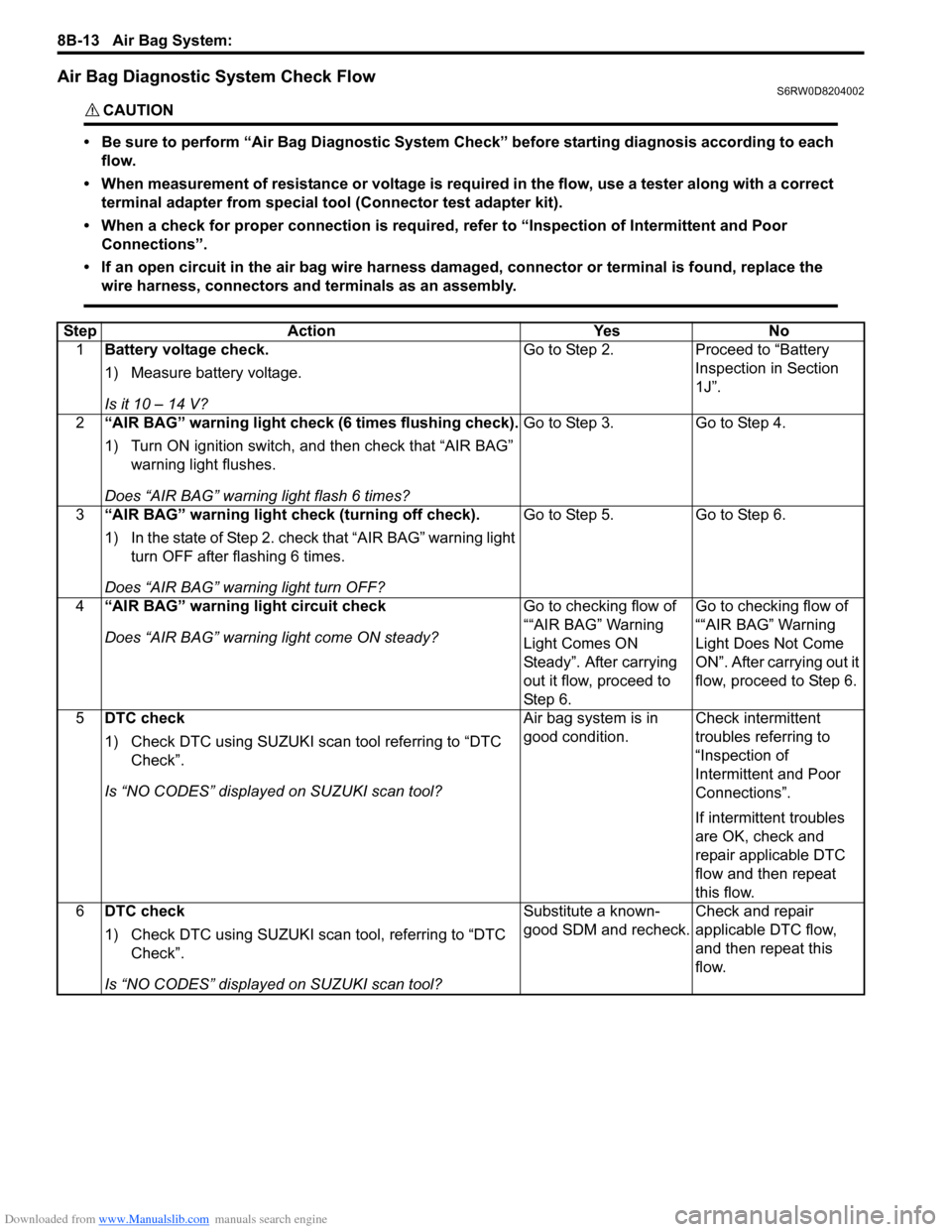
Air Bag Diagnostic System Check FlowS6RW0D8204002
CAUTION!
• Be sure to perform “Air Bag Diagnostic System Check” before starting diagnosis according to each
flow.
• When measurement of resistance or voltage is required in the flow, use a tester along with a correct
terminal adapter from special tool (Connector test adapter kit).
• When a check for proper connection is required, refer to “Inspection of Intermittent and Poor
Connections”.
• If an open circuit in the air bag wire harness damaged, connector or terminal is found, replace the
wire harness, connectors and terminals as an assembly.
Step Action Yes No
1Battery voltage check.
1) Measure battery voltage.
Is it 10 – 14 V?Go to Step 2. Proceed to “Battery
Inspection in Section
1J”.
2“AIR BAG” warning light check (6 times flushing check).
1) Turn ON ignition switch, and then check that “AIR BAG”
warning light flushes.
Does “AIR BAG” warning light flash 6 times?Go to Step 3. Go to Step 4.
3“AIR BAG” warning light check (turning off check).
1) In the state of Step 2. check that “AIR BAG” warning light
turn OFF after flashing 6 times.
Does “AIR BAG” warning light turn OFF?Go to Step 5. Go to Step 6.
4“AIR BAG” warning light circuit check
Does “AIR BAG” warning light come ON steady?Go to checking flow of
““AIR BAG” Warning
Light Comes ON
Steady”. After carrying
out it flow, proceed to
St ep 6 .Go to checking flow of
““AIR BAG” Warning
Light Does Not Come
ON”. After carrying out it
flow, proceed to Step 6.
5DTC check
1) Check DTC using SUZUKI scan tool referring to “DTC
Check”.
Is “NO CODES” displayed on SUZUKI scan tool?Air bag system is in
good condition.Check intermittent
troubles referring to
“Inspection of
Intermittent and Poor
Connections”.
If intermittent troubles
are OK, check and
repair applicable DTC
flow and then repeat
this flow.
6DTC check
1) Check DTC using SUZUKI scan tool, referring to “DTC
Check”.
Is “NO CODES” displayed on SUZUKI scan tool?Substitute a known-
good SDM and recheck.Check and repair
applicable DTC flow,
and then repeat this
flow.
Page 1053 of 1556
Downloaded from www.Manualslib.com manuals search engine Air Bag System: 8B-14
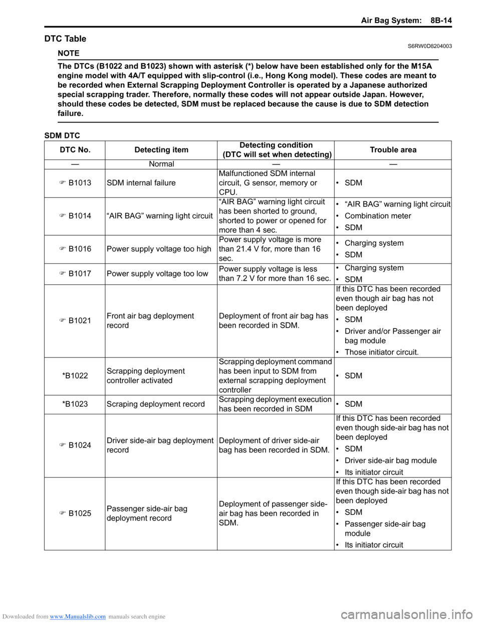
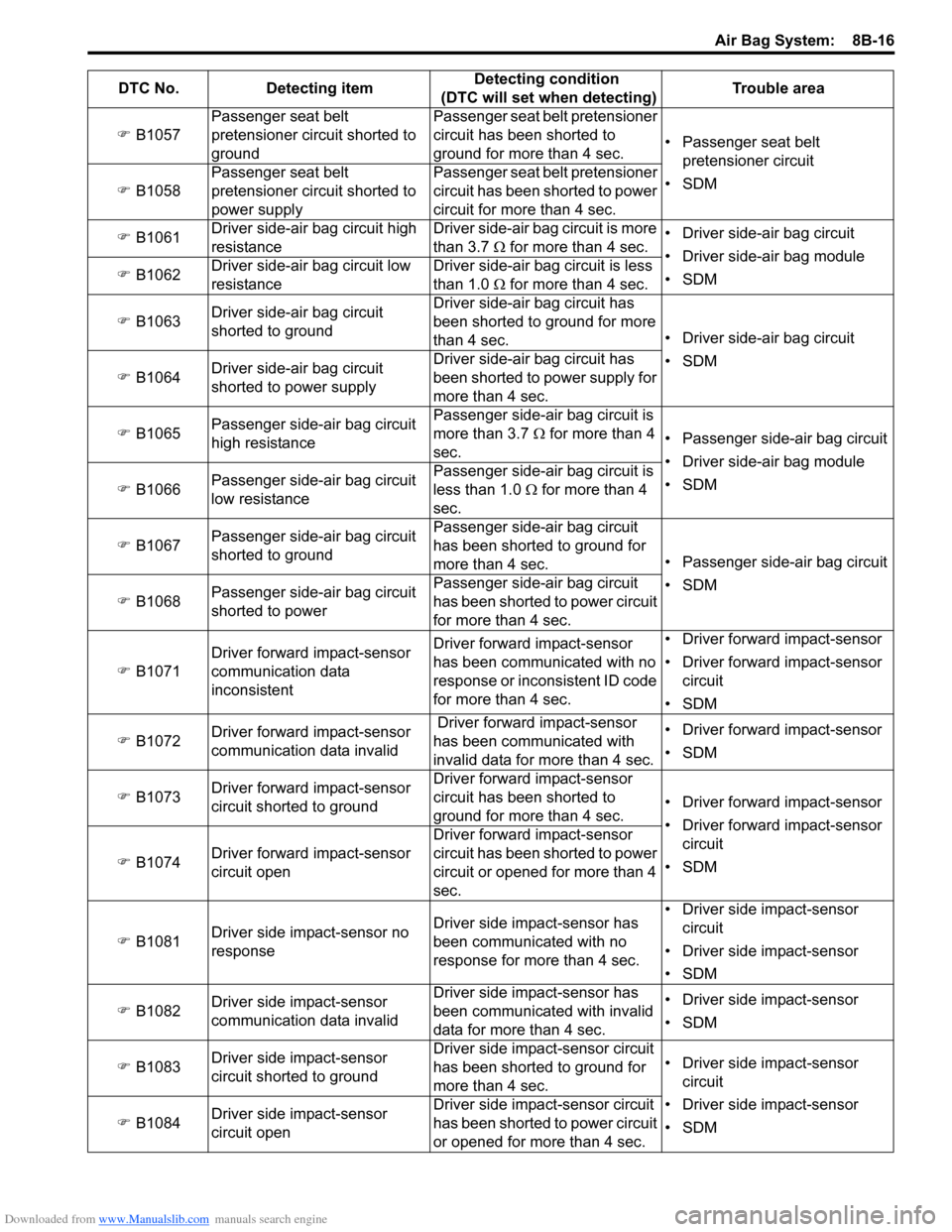
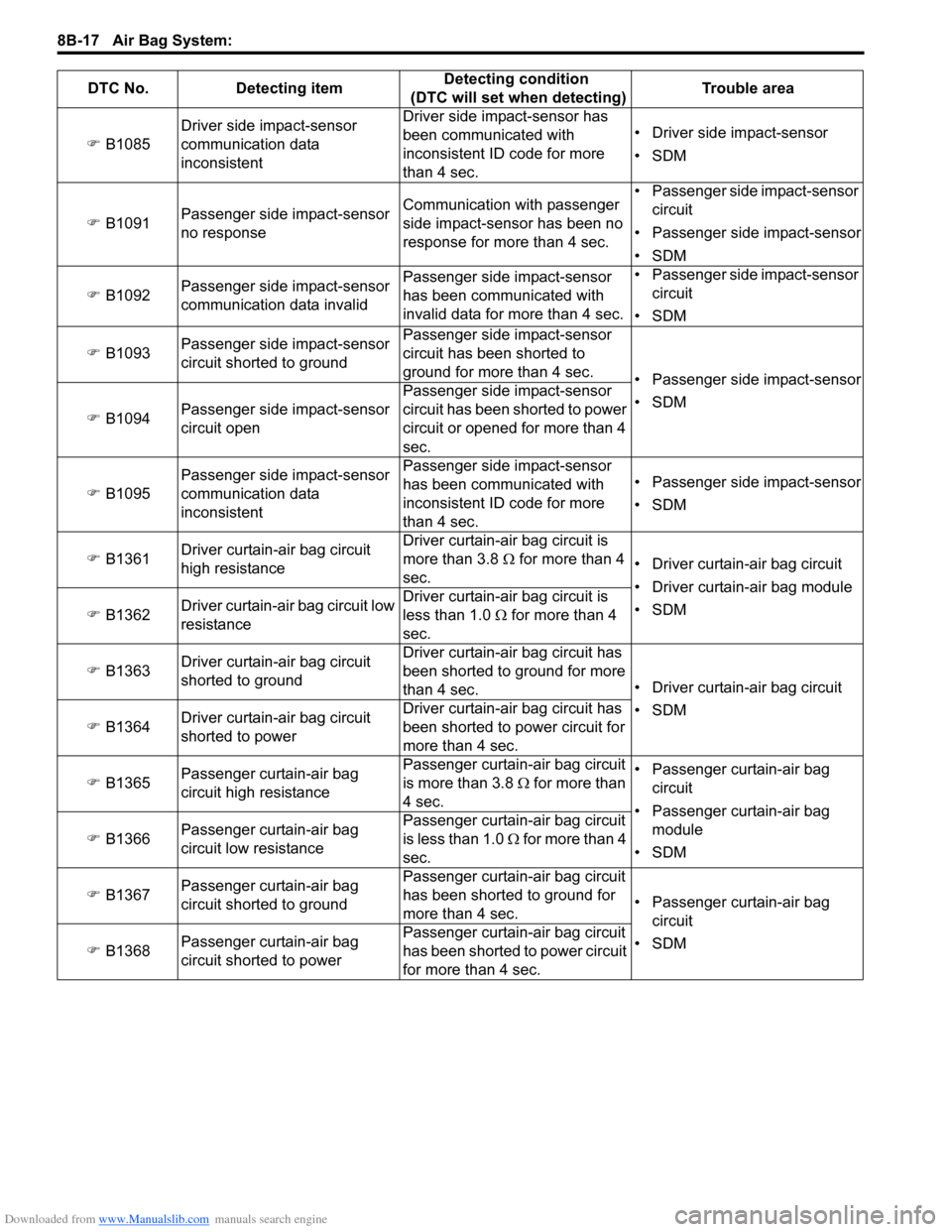
DTC TableS6RW0D8204003
NOTE
The DTCs (B1022 and B1023) shown with asterisk (*) below have been established only for the M15A
engine model with 4A/T equipped with slip-control (i.e., Hong Kong model). These codes are meant to
be recorded when External Scrapping Deployment Controller is operated by a Japanese authorized
special scrapping trader. Therefore, normally these codes will not appear outside Japan. However,
should these codes be detected, SDM must be replaced because the cause is due to SDM detection
failure.
SDM DTC
DTC No. Detecting itemDetecting condition
(DTC will set when detecting)Trouble area
—Normal — —
�) B1013 SDM internal failureMalfunctioned SDM internal
circuit, G sensor, memory or
CPU.•SDM
�) B1014 “AIR BAG” warning light circuit“AIR BAG” warning light circuit
has been shorted to ground,
shorted to power or opened for
more than 4 sec.• “AIR BAG” warning light circuit
• Combination meter
•SDM
�) B1016 Power supply voltage too highPower supply voltage is more
than 21.4 V for, more than 16
sec.• Charging system
•SDM
�) B1017 Power supply voltage too lowPower supply voltage is less
than 7.2 V for more than 16 sec.• Charging system
•SDM
�) B1021Front air bag deployment
recordDeployment of front air bag has
been recorded in SDM.If this DTC has been recorded
even though air bag has not
been deployed
•SDM
• Driver and/or Passenger air
bag module
• Those initiator circuit.
*B1022Scrapping deployment
controller activatedScrapping deployment command
has been input to SDM from
external scrapping deployment
controller•SDM
*B1023 Scraping deployment recordScrapping deployment execution
has been recorded in SDM•SDM
�) B1024Driver side-air bag deployment
recordDeployment of driver side-air
bag has been recorded in SDM.If this DTC has been recorded
even though side-air bag has not
been deployed
•SDM
• Driver side-air bag module
• Its initiator circuit
�) B1025Passenger side-air bag
deployment recordDeployment of passenger side-
air bag has been recorded in
SDM.If this DTC has been recorded
even though side-air bag has not
been deployed
•SDM
• Passenger side-air bag
module
• Its initiator circuit
Page 1054 of 1556
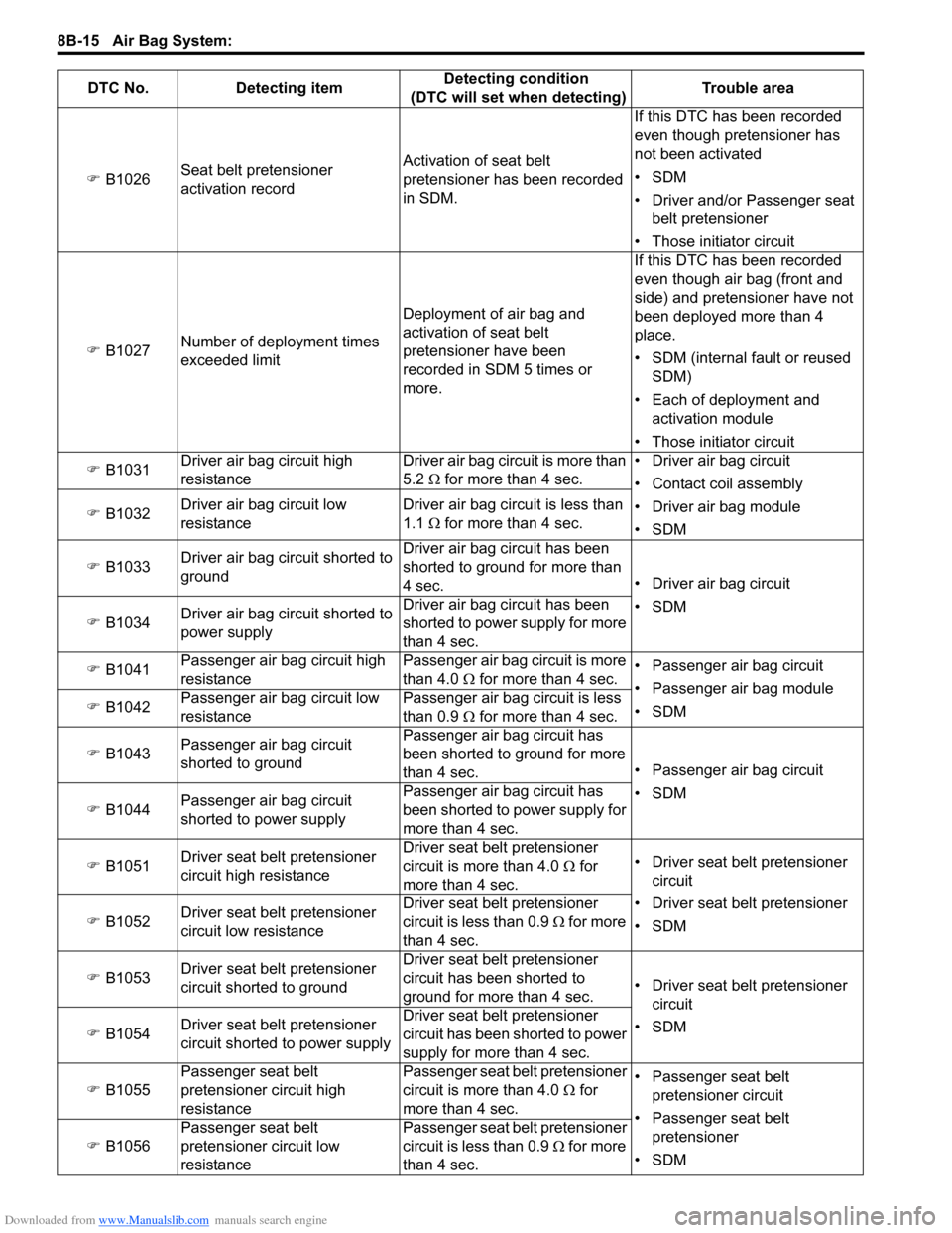
Downloaded from www.Manualslib.com manuals search engine 8B-15 Air Bag System:
�) B1026Seat belt pretensioner
activation recordActivation of seat belt
pretensioner has been recorded
in SDM.If this DTC has been recorded
even though pretensioner has
not been activated
•SDM
• Driver and/or Passenger seat
belt pretensioner
• Those initiator circuit
�) B1027Number of deployment times
exceeded limitDeployment of air bag and
activation of seat belt
pretensioner have been
recorded in SDM 5 times or
more.If this DTC has been recorded
even though air bag (front and
side) and pretensioner have not
been deployed more than 4
place.
• SDM (internal fault or reused
SDM)
• Each of deployment and
activation module
• Those initiator circuit
�) B1031Driver air bag circuit high
resistanceDriver air bag circuit is more than
5.2 Ω for more than 4 sec.• Driver air bag circuit
• Contact coil assembly
• Driver air bag module
•SDM �) B1032Driver air bag circuit low
resistanceDriver air bag circuit is less than
1.1 Ω for more than 4 sec.
�) B1033Driver air bag circuit shorted to
groundDriver air bag circuit has been
shorted to ground for more than
4 sec.• Driver air bag circuit
•SDM
�) B1034Driver air bag circuit shorted to
power supplyDriver air bag circuit has been
shorted to power supply for more
than 4 sec.
�) B1041Passenger air bag circuit high
resistancePassenger air bag circuit is more
than 4.0 Ω for more than 4 sec.• Passenger air bag circuit
• Passenger air bag module
•SDM �) B1042Passenger air bag circuit low
resistancePassenger air bag circuit is less
than 0.9 Ω for more than 4 sec.
�) B1043Passenger air bag circuit
shorted to groundPassenger air bag circuit has
been shorted to ground for more
than 4 sec.• Passenger air bag circuit
•SDM
�) B1044Passenger air bag circuit
shorted to power supplyPassenger air bag circuit has
been shorted to power supply for
more than 4 sec.
�) B1051Driver seat belt pretensioner
circuit high resistance Driver seat belt pretensioner
circuit is more than 4.0 Ω for
more than 4 sec.• Driver seat belt pretensioner
circuit
• Driver seat belt pretensioner
•SDM �) B1052Driver seat belt pretensioner
circuit low resistance Driver seat belt pretensioner
circuit is less than 0.9 Ω for more
than 4 sec.
�) B1053Driver seat belt pretensioner
circuit shorted to groundDriver seat belt pretensioner
circuit has been shorted to
ground for more than 4 sec.• Driver seat belt pretensioner
circuit
•SDM
�) B1054Driver seat belt pretensioner
circuit shorted to power supplyDriver seat belt pretensioner
circuit has been shorted to power
supply for more than 4 sec.
�) B1055Passenger seat belt
pretensioner circuit high
resistance Passenger seat belt pretensioner
circuit is more than 4.0 Ω for
more than 4 sec.• Passenger seat belt
pretensioner circuit
• Passenger seat belt
pretensioner
•SDM �) B1056Passenger seat belt
pretensioner circuit low
resistancePassenger seat belt pretensioner
circuit is less than 0.9 Ω for more
than 4 sec. DTC No. Detecting itemDetecting condition
(DTC will set when detecting)Trouble area
Page 1055 of 1556
Downloaded from www.Manualslib.com manuals search engine Air Bag System: 8B-16
�) B1057Passenger seat belt
pretensioner circuit shorted to
groundPassenger seat belt pretensioner
circuit has been shorted to
ground for more than 4 sec.• Passenger seat belt
pretensioner circuit
•SDM
�) B1058Passenger seat belt
pretensioner circuit shorted to
power supplyPassenger seat belt pretensioner
circuit has been shorted to power
circuit for more than 4 sec.
�) B1061Driver side-air bag circuit high
resistance Driver side-air bag circuit is more
than 3.7 Ω for more than 4 sec.• Driver side-air bag circuit
• Driver side-air bag module
•SDM �) B1062Driver side-air bag circuit low
resistance Driver side-air bag circuit is less
than 1.0 Ω for more than 4 sec.
�) B1063Driver side-air bag circuit
shorted to groundDriver side-air bag circuit has
been shorted to ground for more
than 4 sec.• Driver side-air bag circuit
•SDM
�) B1064Driver side-air bag circuit
shorted to power supplyDriver side-air bag circuit has
been shorted to power supply for
more than 4 sec.
�) B1065Passenger side-air bag circuit
high resistance Passenger side-air bag circuit is
more than 3.7 Ω for more than 4
sec.• Passenger side-air bag circuit
• Driver side-air bag module
•SDM
�) B1066Passenger side-air bag circuit
low resistance Passenger side-air bag circuit is
less than 1.0 Ω for more than 4
sec.
�) B1067Passenger side-air bag circuit
shorted to groundPassenger side-air bag circuit
has been shorted to ground for
more than 4 sec.• Passenger side-air bag circuit
•SDM
�) B1068Passenger side-air bag circuit
shorted to powerPassenger side-air bag circuit
has been shorted to power circuit
for more than 4 sec.
�) B1071Driver forward impact-sensor
communication data
inconsistent Driver forward impact-sensor
has been communicated with no
response or inconsistent ID code
for more than 4 sec.• Driver forward impact-sensor
• Driver forward impact-sensor
circuit
•SDM
�) B1072Driver forward impact-sensor
communication data invalid Driver forward impact-sensor
has been communicated with
invalid data for more than 4 sec.• Driver forward impact-sensor
•SDM
�)
B1073Driver forward impact-sensor
circuit shorted to groundDriver forward impact-sensor
circuit has been shorted to
ground for more than 4 sec.• Driver forward impact-sensor
• Driver forward impact-sensor
circuit
•SDM �) B1074Driver forward impact-sensor
circuit openDriver forward impact-sensor
circuit has been shorted to power
circuit or opened for more than 4
sec.
�) B1081Driver side impact-sensor no
responseDriver side impact-sensor has
been communicated with no
response for more than 4 sec.• Driver side impact-sensor
circuit
• Driver side impact-sensor
•SDM
�) B1082Driver side impact-sensor
communication data invalidDriver side impact-sensor has
been communicated with invalid
data for more than 4 sec.• Driver side impact-sensor
•SDM
�) B1083Driver side impact-sensor
circuit shorted to groundDriver side impact-sensor circuit
has been shorted to ground for
more than 4 sec.• Driver side impact-sensor
circuit
• Driver side impact-sensor
•SDM �) B1084Driver side impact-sensor
circuit openDriver side impact-sensor circuit
has been shorted to power circuit
or opened for more than 4 sec. DTC No. Detecting itemDetecting condition
(DTC will set when detecting)Trouble area
Page 1056 of 1556
Downloaded from www.Manualslib.com manuals search engine 8B-17 Air Bag System:
�) B1085Driver side impact-sensor
communication data
inconsistent Driver side impact-sensor has
been communicated with
inconsistent ID code for more
than 4 sec.• Driver side impact-sensor
•SDM
�) B1091Passenger side impact-sensor
no responseCommunication with passenger
side impact-sensor has been no
response for more than 4 sec.• Passenger side impact-sensor
circuit
• Passenger side impact-sensor
•SDM
�) B1092Passenger side impact-sensor
communication data invalidPassenger side impact-sensor
has been communicated with
invalid data for more than 4 sec.• Passenger side impact-sensor
circuit
•SDM
�) B1093Passenger side impact-sensor
circuit shorted to groundPassenger side impact-sensor
circuit has been shorted to
ground for more than 4 sec.
• Passenger side impact-sensor
•SDM
�) B1094Passenger side impact-sensor
circuit openPassenger side impact-sensor
circuit has been shorted to power
circuit or opened for more than 4
sec.
�) B1095Passenger side impact-sensor
communication data
inconsistentPassenger side impact-sensor
has been communicated with
inconsistent ID code for more
than 4 sec.• Passenger side impact-sensor
•SDM
�) B1361Driver curtain-air bag circuit
high resistanceDriver curtain-air bag circuit is
more than 3.8 Ω for more than 4
sec. • Driver curtain-air bag circuit
• Driver curtain-air bag module
•SDM
�) B1362Driver curtain-air bag circuit low
resistanceDriver curtain-air bag circuit is
less than 1.0 Ω for more than 4
sec.
�) B1363Driver curtain-air bag circuit
shorted to groundDriver curtain-air bag circuit has
been shorted to ground for more
than 4 sec.• Driver curtain-air bag circuit
•SDM
�) B1364Driver curtain-air bag circuit
shorted to powerDriver curtain-air bag circuit has
been shorted to power circuit for
more than 4 sec.
�) B1365Passenger curtain-air bag
circuit high resistancePassenger curtain-air bag circuit
is more than 3.8 Ω for more than
4 sec.• Passenger curtain-air bag
circuit
• Passenger curtain-air bag
module
•SDM �) B1366Passenger curtain-air bag
circuit low resistancePassenger curtain-air bag circuit
is less than 1.0 Ω for more than 4
sec.
�) B1367Passenger curtain-air bag
circuit shorted to groundPassenger curtain-air bag circuit
has been shorted to ground for
more than 4 sec.• Passenger curtain-air bag
circuit
•SDM
�) B1368Passenger curtain-air bag
circuit shorted to powerPassenger curtain-air bag circuit
has been shorted to power circuit
for more than 4 sec. DTC No. Detecting itemDetecting condition
(DTC will set when detecting)Trouble area
Page 1057 of 1556
Downloaded from www.Manualslib.com manuals search engine Air Bag System: 8B-18
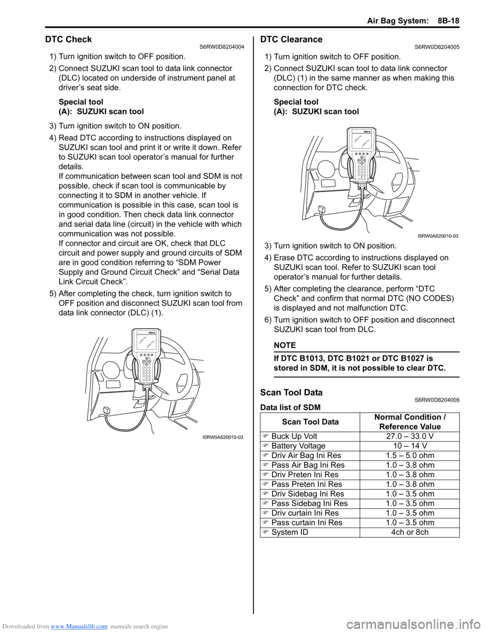
DTC CheckS6RW0D8204004
1) Turn ignition switch to OFF position.
2) Connect SUZUKI scan tool to data link connector
(DLC) located on underside of instrument panel at
driver’s seat side.
Special tool
(A): SUZUKI scan tool
3) Turn ignition switch to ON position.
4) Read DTC according to instructions displayed on
SUZUKI scan tool and print it or write it down. Refer
to SUZUKI scan tool operator’s manual for further
details.
If communication between scan tool and SDM is not
possible, check if scan tool is communicable by
connecting it to SDM in another vehicle. If
communication is possible in this case, scan tool is
in good condition. Then check data link connector
and serial data line (circuit) in the vehicle with which
communication was not possible.
If connector and circuit are OK, check that DLC
circuit and power supply and ground circuits of SDM
are in good condition referring to “SDM Power
Supply and Ground Circuit Check” and “Serial Data
Link Circuit Check”.
5) After completing the check, turn ignition switch to
OFF position and disconnect SUZUKI scan tool from
data link connector (DLC) (1).
DTC ClearanceS6RW0D8204005
1) Turn ignition switch to OFF position.
2) Connect SUZUKI scan tool to data link connector
(DLC) (1) in the same manner as when making this
connection for DTC check.
Special tool
(A): SUZUKI scan tool
3) Turn ignition switch to ON position.
4) Erase DTC according to instructions displayed on
SUZUKI scan tool. Refer to SUZUKI scan tool
operator’s manual for further details.
5) After completing the clearance, perform “DTC
Check” and confirm that normal DTC (NO CODES)
is displayed and not malfunction DTC.
6) Turn ignition switch to OFF position and disconnect
SUZUKI scan tool from DLC.
NOTE
If DTC B1013, DTC B1021 or DTC B1027 is
stored in SDM, it is not possible to clear DTC.
Scan Tool DataS6RW0D8204006
Data list of SDM
I5RW0A820010-03
Scan Tool DataNormal Condition /
Reference Value
�) Buck Up Volt 27.0 – 33.0 V
�) Battery Voltage 10 – 14 V
�) Driv Air Bag Ini Res 1.5 – 5.0 ohm
�) Pass Air Bag Ini Res 1.0 – 3.8 ohm
�) Driv Preten Ini Res 1.0 – 3.8 ohm
�) Pass Preten Ini Res 1.0 – 3.8 ohm
�) Driv Sidebag Ini Res 1.0 – 3.5 ohm
�) Pass Sidebag Ini Res 1.0 – 3.5 ohm
�) Driv curtain Ini Res 1.0 – 3.5 ohm
�) Pass curtain Ini Res 1.0 – 3.5 ohm
�) System ID 4ch or 8ch
I5RW0A820010-03
Page 1059 of 1556
Downloaded from www.Manualslib.com manuals search engine Air Bag System: 8B-20
Troubleshooting
Step Action Yes No
1Was “Air Bag Diagnostic System Check Flow” performed?Go to Step 2. Go to “Air Bag
Diagnostic System
Check Flow”.
2SDM power supply and ground circuit check
1) Check SDM power supply and ground circuit referring to
“SDM Power Supply and Ground Circuit Check”.
Is SDM power supply and ground circuit in good condition?Go to Step 3. Repair defective power
supply and ground
circuit.
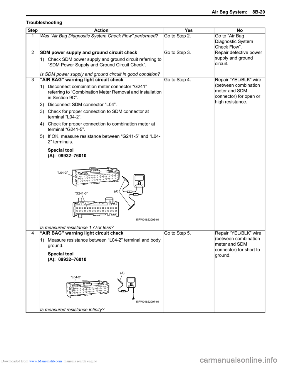
3“AIR BAG” warning light circuit check
1) Disconnect combination meter connector “G241”
referring to “Combination Meter Removal and Installation
in Section 9C”.
2) Disconnect SDM connector “L04”.
3) Check for proper connection to SDM connector at
terminal “L04-2”.
4) Check for proper connection to combination meter at
terminal “G241-5”.
5) If OK, measure resistance between “G241-5” and “L04-
2” terminals.
Special tool
(A): 09932–76010
Is measured resistance 1
Ω or less?Go to Step 4. Repair “YEL/BLK” wire
(between combination
meter and SDM
connector) for open or
high resistance.
4“AIR BAG” warning light circuit check
1) Measure resistance between “L04-2” terminal and body
ground.
Special tool
(A): 09932–76010
Is measured resistance infinity?Go to Step 5. Repair “YEL/BLK” wire
(between combination
meter and SDM
connector) for short to
ground.
(A)
“L04-2”
“G241-5”
I7RW01822006-01
“L04-2”(A)
I7RW01822007-01