2006 SUZUKI SX4 speed
[x] Cancel search: speedPage 995 of 1556

Downloaded from www.Manualslib.com manuals search engine Air Conditioning System: Automatic Type 7B-55
Scan Tool DataS6RW0D7224008
As the data values given in the following are standard values estimated on the basis of values obtained from the
normally operation vehicles by using a scan tool, use them as reference values. Even when the vehicles are in good
condition, there may be cases where the checked values do not fall within each specifies data range. Therefore,
judgement as abnormal should not be made by checking with these data alone. �) B1551Serial communication
circuit• HVAC control module maintains last
normal value of outside air
temperature.
4 seconds after, HVAC control
module assuming that outside air
temperature is 20 °C (68 °F).
• HVAC control module maintains last
normal value of engine coolant
temperature.
4 seconds after, HVAC control
module assuming that engine
coolant temperature is 80 °C (176
°F).
• HVAC control module controls
actuators assuming that vehicle
speed is 40 km/h (25 mph).
• HVAC control module controls
actuators assuming that engine type
signal is J20.
• HVAC control module controls
actuators assuming that
combination meter spec signal is
US.HVAC control module controls actuators
assuming that outside air temperature is
20 °C (68 °F), engine coolant
temperature is 80 °C (176 °F), vehicle
speed is 40 km/h (25 mph), engine type
signal is J20 and combination meter spec
signal is US. �) B1552HVAC control module
check sum error
�) B1553CAN communication
circuit
�) B1557 VSS signal failureHVAC control module controls actuators assuming that vehicle speed is 40 km/h
(25 mph).
�) B1561 ECT signal failureHVAC control module maintains last
normal value of engine coolant
temperature. 4 seconds after, HVAC
control module assuming that engine
coolant temperature is 80 °C (176 °F).HVAC control module controls actuators
assuming that engine
coolant temperature is 80 °C (176 °F).
�) B1562Outside air
temperature signal
failureHVAC control module maintains last
normal value of outside air
temperature.
4 seconds after, HVAC control module
assuming that outside air temperature
is 20 °C (68 °F).HVAC control module controls actuators
assuming that outside air temperature is
20 °C (68 °F).
�) B1570Engine type signal
failureHVAC control module controls actuators assuming that engine type signal is J20.
�) B1571Combination meter
spec signal failureHVAC control module controls actuators assuming that combination meter spec
signal is US. DTC No. Trouble AreaFail-Safe Operation
When ignition switch is turned ON
after malfunction is already detectedWhen malfunction is detected during
ignition switch is ON
Scan Tool Data ConditionNormal Condition / Reference
Va l u e
�) TEMP CONT
SWITCHIgnition switch turned ON and temperature selector
at maximum cool positionMAX Cool (Selected position of
temperature selector is displayed)
�) CABIN
TEMPERATUREIgnition switch turned ON In-car temperature is displayed
�) OUTSIDE AIR TEMP Ignition switch turned ON Outside air temperature is displayed
�) EVAPORATOR
TEMPIgnition switch turned ON Evaporator temperature is displayed
Page 996 of 1556

Downloaded from www.Manualslib.com manuals search engine 7B-56 Air Conditioning System: Automatic Type
Scan Tool Data Definitions
TEMP CONT SWITCH: (Temperature control selector
position, Max Cool, °C / °F, Max Hot): This
parameter indicates the selected position of
temperature control selector.
CABIN TEMPERATURE: (In-car temperature, °C, °F):
This parameter indicates the in-car temperature
detected by inside air temperature sensor.OUTSIDE AIR TEMP (Outside air temperature, °C,
°F): This parameter indicates the outside air
temperature detected by outside air temperature
sensor.
EVAPORATOR TEMP (Evaporator temperature, °C,
°F): This parameter indicates the temperature of air
passed through evaporator.
COOLANT TEMP (Engine Coolant Temperature °C,
°F): This parameter indicates the engine coolant
temperature detected by engine coolant temperature
sensor. �) COOLANT TEMP
Ignition switch turned ONEngine coolant temperature is
displayed
�) SUN LOAD Reference value depends on the situation 0 W/m
2 – 1988 W/m2
�)MODE CONT
SWITCHIgnition switch turned ON and air flow selector at
AUTO positionAUTO (Selected position of air flow
selector is displayed)
�) FAN CONT SWITCHIgnition switch turned ON and blower speed selector
at AUTO positionAUTO (Selected position of blower
speed selector is displayed)
�) FAN DESIRED VOLTIgnition switch turned ON and blower speed selector
at HighApprox. 12.0 V
Ignition switch turned ON and blower speed selector
at LowApprox. 4.0 V
�) AIR MIX POS SENIgnition switch turned ON and temperature selector
at maximum cool positionApprox. 0.5 V
Ignition switch turned ON and temperature selector
at maximum hot positionApprox. 4.5 V
�)MODE POS SENSORIgnition switch turned ON and air flow selector at
DEF positionApprox. 4.5 V
Ignition switch turned ON and air flow selector at
VENT positionApprox. 0.5 V
�) A/C CONT SIGA/C switch turned ON, blower speed selector at other
than OFF position with engine runningON
A/C switch turned OFF with engine running OFF
�) BLOWER LOAD SIGIgnition switch turned ON, blower speed selector at
other than OFF positionON
Ignition switch turned ON, blower speed selector at
OFF positionOFF
�) AIR INTAKE MODEIgnition switch turned ON and air intake selector at
fresh air (FRE) positionFRE
Ignition switch turned ON and air intake selector at
recirculation air (REC) positionREC
Ignition switch turned ON, air flow selector and
blower speed selector at AUTO positionAUTO
�) REFRIGERANT
PRESSUREA/C ON (A/C is operating) with engine running at
ambient temperature 30 °C (86 °F)1130 – 1560 kPa (For details, refer to
pressure of high pressure gauge
under “A/C System Performance
Inspection”)
A/C OFF (A/C is not operating) with engine running
at ambient temperature 30 °C (86 °F) and engine
coolant temperature 90 °C (194 °F) – 100 °C (212
°F)600 – 1000 kPa after longer than 10
minute for A/C switch turned off
�) A/C COMP CLUTCHA/C switch turned ON, blower speed selector at other
than OFF position with engine runningON
A/C switch turned OFF with engine running OFF
�) VEHICLE SPEED At stop with ignition switch turned ON 0 km/h (0 mph)
�) ENGINE TYPE Ignition switch turned ON Engine type is displayed.
�) METER SPEC Ignition switch turned ONCombination meter spec is displayed. Scan Tool Data ConditionNormal Condition / Reference
Va l u e
Page 997 of 1556

Downloaded from www.Manualslib.com manuals search engine Air Conditioning System: Automatic Type 7B-57
SUN LOAD (W/m2): This parameter indicates the
amount of sunlight detected by sunload sensor.
MODE CONT SWITCH (Air flow selector position,
AUTO, FACE, B/L, FOOT, D/F, DEF): This
parameter indicates the selected position of air flow
selector.
FAN CONT SWITCH (Blower speed selector, AUTO,
OFF, 1st – 8th): This parameter indicates the
selected position of blower speed selector.
FAN DESIRE VOLT (Fan desired voltage, V): This
parameter indicates the consumption voltage of
blower motor.
AIR MIX POS SENSOR (Temperature control
actuator position sensor, V): This parameter
indicates the input signal from position sensor in
temperature control actuator.
MODE POS SENSOR (Air flow control actuator
position sensor, V): This parameter indicates the
input signal from position sensor in air flow control
actuator.
A/C CONT SIG (A/C control signal, ON, OFF): This
parameter indicates the state of A/C switch.BLOWER LOAD SIG (Blower fan load signal, ON,
OFF): ON: Position of blower speed selector is 1st
position or more.
OFF: Position of blower speed selector is OFF
position.
AIR INTAKE MODE (Air intake selector position,
AUTO, FRE, REC): This parameter indicates the
selected position of air intake selector.
REFRIGERANT PRESSURE (A/C refrigerant absolute
pressure, kPa): This parameter indicates the A/C
refrigerant absolute pressure calculated by ECM
A/C COMP CLUCH (A/C compressor magnet clutch,
ON, OFF): This parameter indicates the state of the
A/C compressor magnet clutch.
VEHICLE SPEED (km/h, mph): This parameter
indicates the vehicle speed calculated by ECM.
ENGINE TYPE (Engine type signal, J20, M16 or
M15): This parameter indicates the engine type
signal transmitted by ECM.
METER SPEC (Combination meter spec signal, EU,
UK, US, Canada, DOM): This parameter indicates
the combination meter spec signal transmitted by
combination meter.
Visual InspectionS6RW0D7224009
Check visually the following parts and systems.
DTC B1502: Inside Air Temperature Sensor Circuit MalfunctionS6RW0D7224010
Wiring DiagramInspection item Correction
• Refrigerant leakage and amount
• A/C pipe or hose disconnection,
looseness and
deterioration
• A/C compressor drive belt looseness and damageRefer to “Compressor Drive Belt Inspection
and Adjustment”.
• Battery fluid level and corrosion
of terminal
• Connectors of electric wire harness disconnection and
friction
• Fuses burning
• Parts installation and damage
• Other parts that can be checked visually
5V
G20
1 2 3 4 5 6 7 8 9 10 11 12 13 14
15 16 17 18 19 20 21 24 23 22 25 26 27 28 29 30
ORNORNPNK/BLKG20-10
21
3 [S]
[G]
G20-24
I7RW01722004-01
[S]: Inside air temperature sensor signal circuit 1. HVAC control module 3. To other sensors
[G]: Inside air temperature sensor ground circuit 2. Inside air temperature sensor
Page 1008 of 1556
Downloaded from www.Manualslib.com manuals search engine 7B-68 Air Conditioning System: Automatic Type
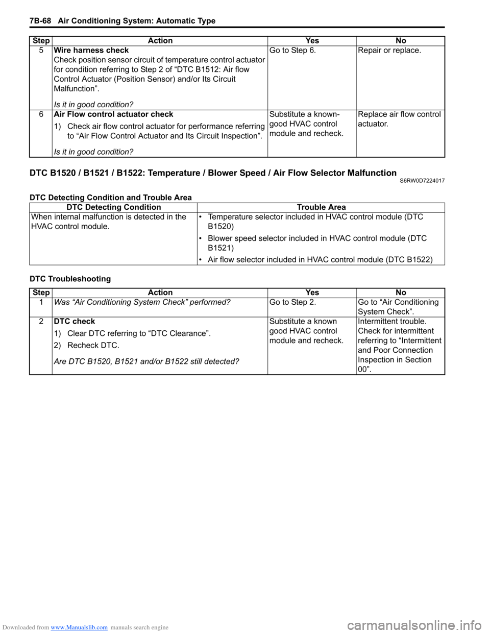
DTC B1520 / B1521 / B1522: Temperature / Blower Speed / Air Flow Selector MalfunctionS6RW0D7224017
DTC Detecting Condition and Trouble Area
DTC Troubleshooting5Wire harness check
Check position sensor circuit of temperature control actuator
for condition referring to Step 2 of “DTC B1512: Air flow
Control Actuator (Position Sensor) and/or Its Circuit
Malfunction”.
Is it in good condition?Go to Step 6. Repair or replace.
6Air Flow control actuator check
1) Check air flow control actuator for performance referring
to “Air Flow Control Actuator and Its Circuit Inspection”.
Is it in good condition?Substitute a known-
good HVAC control
module and recheck.Replace air flow control
actuator. Step Action Yes No
DTC Detecting Condition Trouble Area
When internal malfunction is detected in the
HVAC control module.• Temperature selector included in HVAC control module (DTC
B1520)
• Blower speed selector included in HVAC control module (DTC
B1521)
• Air flow selector included in HVAC control module (DTC B1522)
Step Action Yes No
1Was “Air Conditioning System Check” performed?Go to Step 2. Go to “Air Conditioning
System Check”.
2DTC check
1) Clear DTC referring to “DTC Clearance”.
2) Recheck DTC.
Are DTC B1520, B1521 and/or B1522 still detected?Substitute a known
good HVAC control
module and recheck.Intermittent trouble.
Check for intermittent
referring to “Intermittent
and Poor Connection
Inspection in Section
00”.
Page 1012 of 1556
Downloaded from www.Manualslib.com manuals search engine 7B-72 Air Conditioning System: Automatic Type
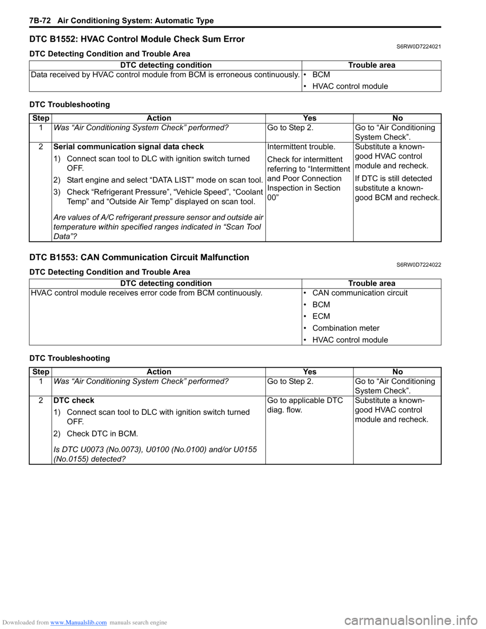
DTC B1552: HVAC Control Module Check Sum ErrorS6RW0D7224021
DTC Detecting Condition and Trouble Area
DTC Troubleshooting
DTC B1553: CAN Communication Circuit MalfunctionS6RW0D7224022
DTC Detecting Condition and Trouble Area
DTC TroubleshootingDTC detecting condition Trouble area
Data received by HVAC control module from BCM is erroneous continuously. • BCM
• HVAC control module
Step Action Yes No
1Was “Air Conditioning System Check” performed?Go to Step 2. Go to “Air Conditioning
System Check”.
2Serial communication signal data check
1) Connect scan tool to DLC with ignition switch turned
OFF.
2) Start engine and select “DATA LIST” mode on scan tool.
3) Check “Refrigerant Pressure”, “Vehicle Speed”, “Coolant
Temp” and “Outside Air Temp” displayed on scan tool.
Are values of A/C refrigerant pressure sensor and outside air
temperature within specified ranges indicated in “Scan Tool
Data”?Intermittent trouble.
Check for intermittent
referring to “Intermittent
and Poor Connection
Inspection in Section
00”Substitute a known-
good HVAC control
module and recheck.
If DTC is still detected
substitute a known-
good BCM and recheck.
DTC detecting condition Trouble area
HVAC control module receives error code from BCM continuously. • CAN communication circuit
•BCM
•ECM
• Combination meter
• HVAC control module
Step Action Yes No
1Was “Air Conditioning System Check” performed?Go to Step 2. Go to “Air Conditioning
System Check”.
2DTC check
1) Connect scan tool to DLC with ignition switch turned
OFF.
2) Check DTC in BCM.
Is DTC U0073 (No.0073), U0100 (No.0100) and/or U0155
(No.0155) detected?Go to applicable DTC
diag. flow.Substitute a known-
good HVAC control
module and recheck.
Page 1017 of 1556
Downloaded from www.Manualslib.com manuals search engine Air Conditioning System: Automatic Type 7B-77
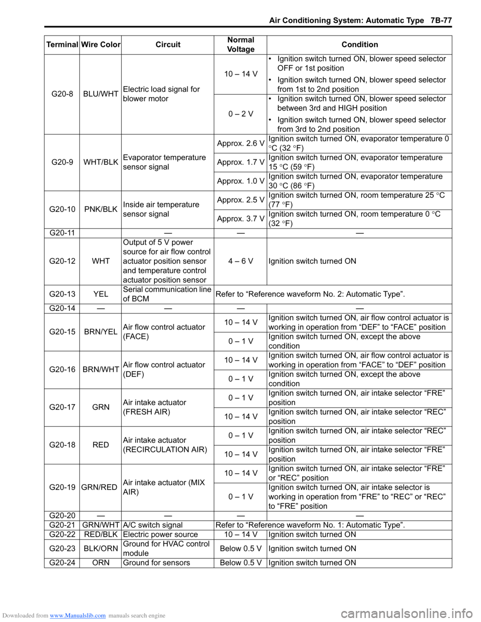
G20-8 BLU/WHTElectric load signal for
blower motor10 – 14 V• Ignition switch turned ON, blower speed selector
OFF or 1st position
• Ignition switch turned ON, blower speed selector
from 1st to 2nd position
0 – 2 V• Ignition switch turned ON, blower speed selector
between 3rd and HIGH position
• Ignition switch turned ON, blower speed selector
from 3rd to 2nd position
G20-9 WHT/BLKEvaporator temperature
sensor signalApprox. 2.6 VIgnition switch turned ON, evaporator temperature 0
°C (32 °F)
Approx. 1.7 VIgnition switch turned ON, evaporator temperature
15 °C (59 °F)
Approx. 1.0 VIgnition switch turned ON, evaporator temperature
30 °C (86 °F)
G20-10 PNK/BLKInside air temperature
sensor signalApprox. 2.5 VIgnition switch turned ON, room temperature 25 °C
(77 °F)
Approx. 3.7 VIgnition switch turned ON, room temperature 0 °C
(32 °F)
G20-11 — — —
G20-12 WHTOutput of 5 V power
source for air flow control
actuator position sensor
and temperature control
actuator position sensor4 – 6 V Ignition switch turned ON
G20-13 YELSerial communication line
of BCMRefer to “Reference waveform No. 2: Automatic Type”.
G20-14 — — — —
G20-15 BRN/YELAir flow control actuator
(FACE)10 – 14 VIgnition switch turned ON, air flow control actuator is
working in operation from “DEF” to “FACE” position
0 – 1 VIgnition switch turned ON, except the above
condition
G20-16 BRN/WHTAir flow control actuator
(DEF)10 – 14 VIgnition switch turned ON, air flow control actuator is
working in operation from “FACE” to “DEF” position
0 – 1 VIgnition switch turned ON, except the above
condition
G20-17 GRNAir intake actuator
(FRESH AIR)0 – 1 VIgnition switch turned ON, air intake selector “FRE”
position
10 – 14 VIgnition switch turned ON, air intake selector “REC”
position
G20-18 REDAir intake actuator
(RECIRCULATION AIR)0 – 1 VIgnition switch turned ON, air intake selector “REC”
position
10 – 14 VIgnition switch turned ON, air intake selector “FRE”
position
G20-19 GRN/REDAir intake actuator (MIX
AIR)10 – 14 VIgnition switch turned ON, air intake selector “FRE”
or “REC” position
0 – 1 VIgnition switch turned ON, air intake selector is
working in operation from “FRE” to “REC” or “REC”
to “FRE” position
G20-20 — — — —
G20-21 GRN/WHT A/C switch signal Refer to “Reference waveform No. 1: Automatic Type”.
G20-22 RED/BLK Electric power source 10 – 14 V Ignition switch turned ON
G20-23 BLK/ORNGround for HVAC control
moduleBelow 0.5 V Ignition switch turned ON
G20-24 ORN Ground for sensors Below 0.5 V Ignition switch turned ON Terminal Wire Color CircuitNormal
Vo l ta g eCondition
Page 1018 of 1556
Downloaded from www.Manualslib.com manuals search engine 7B-78 Air Conditioning System: Automatic Type
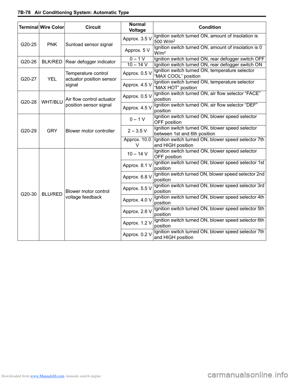
G20-25 PNK Sunload sensor signalApprox. 3.5 VIgnition switch turned ON, amount of insolation is
500 W/m2
Approx. 5 VIgnition switch turned ON, amount of insolation is 0
W/m2
G20-26 BLK/RED Rear defogger indicator0 – 1 V Ignition switch turned ON, rear defogger switch OFF
10 – 14 V Ignition switch turned ON, rear defogger switch ON
G20-27 YELTemperature control
actuator position sensor
signalApprox. 0.5 VIgnition switch turned ON, temperature selector
“MAX COOL” position
Approx. 4.5 VIgnition switch turned ON, temperature selector
“MAX HOT” position
G20-28 WHT/BLUAir flow control actuator
position sensor signalApprox. 0.5 VIgnition switch turned ON, air flow selector “FACE”
position
Approx. 4.5 VIgnition switch turned ON, air flow selector “DEF”
position
G20-29 GRY Blower motor controller0 – 1 VIgnition switch turned ON, blower speed selector
OFF position
2 – 3.5 VIgnition switch turned ON, blower speed selector
between 1st and 6th position
Approx. 10.0
VIgnition switch turned ON, blower speed selector 7th
and HIGH position
G20-30 BLU/REDBlower motor control
voltage feedback10 – 14 VIgnition switch turned ON, blower speed selector
OFF position
Approx. 8.1 VIgnition switch turned ON, blower speed selector 1st
position
Approx. 6.8 VIgnition switch turned ON, blower speed selector 2nd
position
Approx. 5.5 VIgnition switch turned ON, blower speed selector 3rd
position
Approx. 4.0 VIgnition switch turned ON, blower speed selector 4th
position
Approx. 2.6 VIgnition switch turned ON, blower speed selector 5th
position
Approx. 1.2 VIgnition switch turned ON, blower speed selector 6th
position
Approx. 0.2 VIgnition switch turned ON, blower speed selector 7th
and HIGH position Terminal Wire Color CircuitNormal
Vo l ta g eCondition
Page 1034 of 1556
Downloaded from www.Manualslib.com manuals search engine 8A-3 Seat Belts:
Seat Belt with ELR
The seat belt with emergency locking retractor (ELR) is
designed so that it locks immediately (to prevent the
webbing from being pulled out of the retractor any
further) when any of the following items is detected as
exceeding each set value;
• Speed at which the webbing is pulled out of the
retractor.
• Acceleration or deceleration of the vehicle speed.
• Inclination.
Seat Belt with A-ELR
The automatic and emergency locking retractor (A-ELR)
works as an Emergency Locking Retractor (ELR) till its
webbing is pulled all the way out and then on as an
Automatic Locking Retractor (ALR) till it is retracted fully.
ALR: Automatically locks when the webbing is pulled out
from the retractor and allowed to retract even a little.
Then the webbing can not be pulled out any further,
unless it is wound all the way back into the retractor,
which releases the lock and allows the webbing to be
pulled out.
Seat Belt with ELR and Pretensioner
The seat belt with ELR and a pretensioner has a
pretensioner mechanism which operates in linkage with
the air bag in addition to the described ELR.The pretensioner is incorporated in retractor and
controlled by SDM as one of air bag system
components. It will be activated at the same time as the
driver and passenger air bag module when an impact at
the front of vehicle exceeds the specified value.
When servicing seat belt (retractor) with pretensioner, be
sure to observe all WARNINGS and CAUTIONS and
“Precautions on Service and Diagnosis of Air Bag
System in Section 8B”.
CAUTION!
Do not reuse the seat belt pretensioner
(retractor) that has activated. Replace it with
a new seat belt and buckle together as a set.
For checking procedure of its activation,
refer to “Repair and Inspection Required after
Accident in Section 8B”.
Seat Belt Remainder
When driver’s seat belt is unfastened (under the
following conditions), seat belt reminder light inform that
driver’s seat belt is unfastened. Seat belt reminder light
located in combination meter located inside BCM
operate as follows:
• Seat belt reminder light comes on when driver’s seat
belt is unfastened while ignition key switch is at ON
position.
Diagnostic Information and Procedures
Repair and Inspection Required after AccidentS6RW0D8104001
After an accident, whether the seat belt pretensioner has been activated or not, be sure to perform checks and repairs
described on “Repair and Inspection Required after Accident in Section 8B”.