2006 SUZUKI SX4 maintenance
[x] Cancel search: maintenancePage 44 of 1556

Downloaded from www.Manualslib.com manuals search engine 0B-13 Maintenance and Lubrication:
Page 262 of 1556

Downloaded from www.Manualslib.com manuals search engine 1A-212 Engine General Information and Diagnosis:
Repair Instructions
Idle Speed and IAC Throttle Valve Opening
Inspection
S6RW0D1106001
Before idle speed check, make sure of the following.
• Lead wires and hoses of electronic fuel injection and
engine and emission control systems are connected
securely.
• Valve lash is checked according to maintenance
schedule.
• Ignition timing is within specification.
• All accessories (wipers, heater, lights, A/C, etc.) are
out of service.
• Air cleaner has been properly installed and is in good
condition.
• No abnormal air drawn in from air intake system.After all items are confirmed, check idle speed and IAC
throttle opening as follows.NOTE
Before starting engine, place transmission
gear shift lever in “Neutral”, and set parking
brake and block drive wheels.
Step Action Yes No
1Is there DTC(s) of ECT sensor circuit (DTC P0116 / P0117 /
P0118) and/or radiator cooling fan circuit (DTC P0480)?Go to corresponding
DTC flow.Go to Step 2.
2Radiator cooling fan control circuit check
1) Connect scan tool to DLC with ignition switch turned
OFF.
2) Start engine and select “Data List” on scan tool.
3) Warm up engine until coolant temp. is 100 °C, 212 °F or
higher and A/C switch turns OFF (if equipped with A/C).
(If engine coolant temp. dose not rise, check engine
cooling system or ECT sensor.)
Is radiator cooling fan started when engine coolant temp.
reached above temp.?Radiator cooling fan
control system is in
good condition.Perform from Step 2 to
Step 7 in DTC P0480
diag. flow. If OK, Go to
Ste p 3.
3Radiator cooling fan control check
1) Disconnect radiator cooling fan motor connector with
ignition switch turned OFF.
2) Run engine when ECT is over 100 °C, 212 °F.
3) Measure voltage between vehicle body ground and
“BLU/RED” wire terminal of disconnected radiator
cooling fan motor connector.
Is voltage 10 – 14 V?Go to Step 4. “BLU/RED” wire is open
or high resistance
circuit.
4Check radiator cooling fan wire circuit check
1) Turn ignition switch to OFF position.
2) Measure resistance between “BLK” wire terminal of
disconnected radiator cooling fan motor connector and
vehicle body ground.
Is resistance below 1
Ω?Go to Step 5. “BLK” wire is open or
high resistance circuit.
5Radiator cooling fan check
1) Check radiator cooling fan referring to “Radiator Cooling
Fan Assembly On-Vehicle Inspection in Section 1F”.
Is it in good condition?Substitute a known-
good ECM and recheck.Faulty radiator cooling
fan.
Page 428 of 1556

Downloaded from www.Manualslib.com manuals search engine 1K-1 Exhaust System:
Engine
Exhaust System
General Description
Exhaust System DescriptionS6RW0D1B01001
The exhaust system consists of an exhaust manifold, three-way catalytic converter (TWC) in catalyst case, exhaust
pipes, a muffler and seals, gasket and etc.
The three-way catalytic converter is an emission control device added to the exhaust system to lower the levels of
Hydrocarbon (HC), Carbon Monoxide (CO), and Oxides of Nitrogen (NOx) pollutants in the exhaust gas.
Diagnostic Information and Procedures
Exhaust System CheckS6RW0D1B04001
WARNING!
To avoid the danger of being burned, do not touch the exhaust system when the system is hot. Any
service on the exhaust system should be performed when the system is cool.
At every interval of periodic maintenance service, and when vehicle is raised for other service, check exhaust system
as follows:
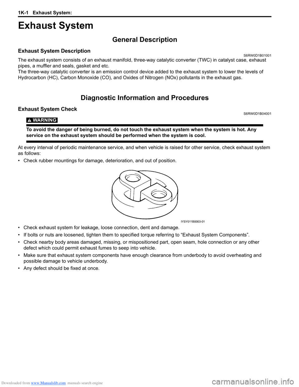
• Check rubber mountings for damage, deterioration, and out of position.
• Check exhaust system for leakage, loose connection, dent and damage.
• If bolts or nuts are loosened, tighten them to specified torque referring to “Exhaust System Components”.
• Check nearby body areas damaged, missing, or mispositioned part, open seam, hole connection or any other
defect which could permit exhaust fumes to seep into vehicle.
• Make sure that exhaust system components have enough clearance from underbody to avoid overheating and
possible damage to vehicle underbody.
• Any defect should be fixed at once.
IYSY011B0003-01
Page 471 of 1556

Downloaded from www.Manualslib.com manuals search engine Wheels and Tires: 2D-2
Replacement Tires
When replacement is necessary, the original equipment
type tire should be used. Refer to the Tire Placard.
Replacement tires should be of the same size, load
range and construction as those originally on the vehicle.
Use of any other size or type tire may affect ride,
handling, speedometer / odometer calibration, vehicle
ground clearance and tire or snow chain clearance to the
body and chassis.
It is recommended that new tires be installed in pairs on
the same axle. If necessary to replace only one tire, it
should be paired with the tire having the most tread, to
equalize braking traction.
WARNING!
Do not mix different types of tires on the
same vehicle such as radial, bias and bias-
belted tires except in emergencies, because
handling may be seriously affected and may
result in loss of control.
The metric term for tire inflation pressure is the kilo
pascal (kPa). Tire pressures is usually printed in both
kPa and kgf/cm
2 on the “Tire Placard”.
Metric tire gauges are available from tool suppliers.
The chart, shown in the table, converts commonly used
inflation pressures from kPa to kgf/cm
2 and psi.
Wheels DescriptionS6RW0D2401002
Wheel Maintenance
Wheel repairs that use welding, heating, or peening are
not approved. All damaged wheels should be replaced.
Replacement Wheels
Wheels must be replaced if they are bent, dented, have
excessive lateral or radial runout, air leak through welds,
have elongated bolt holes, if lug wheel bolts won’t stay
tight, or if they are heavily rusted. Wheels with greater
runout than shown in the following may cause
objectional vibrations.
Replacement wheels must be equivalent to the original
equipment wheels in load capacity, diameter, rim with
offset and mounting configuration. A wheel of improper
size or type may affect wheel and bearing life, brake
cooling, speedometer / odometer calibration, vehicle
ground clearance and tire clearance to body and
chassis.How to Measure Wheel Runout
To measure the wheel runout, it is necessary to use an
accurate dial indicator. The tire may be on or off the
wheel. The wheel should be installed to the wheel
balancer of the like for proper measurement.
Take measurements of both lateral runout “a” and radial
runout “b” at both inside and outside of the rim flange.
With the dial indicator set in place securely, turn the
wheel one full revolution slowly and record every reading
of the indicator.
When the measured runout exceeds the specification
and correction by the balancer adjustment is impossible,
replace the wheel. If the reading is affected by welding,
paint or scratch, it should be ignored.
Lateral runout limit “a”
Aluminum wheel: 0.3 mm (0.012 in.)
Steel wheel: 0.9 mm (0.035 in.)
Radial runout limit “b”
Aluminum wheel: 0.3 mm (0.012 in.)
Steel wheel: 0.7 mm (0.028 in.)
Metric Lug Nuts and Wheel Studs
All models use metric lug nuts and wheel studs.
Metric lug nuts and wheel studs size
M12 x 1.25
If a broken stud is found, see “Front Wheel Hub, Disc,
Bolt and Bearing Check in Section 2B”, “Front Wheel
Hub, Steering Knuckle and Wheel Bearing Removal and
Installation in Section 2B”, “Rear Wheel Hub Assembly
Removal and Installation in Section 2C”. kPa kgf/cm
2psi
Conversion: 1 psi =
6.895 kPa 1 kgf/cm
2 =
98.066 kPa160 1.6 23
180 1.8 26
200 2.0 29
220 2.2 32
240 2.4 35
260 2.6 38
280 2.8 41
300 3.0 44
320 3.2 47
340 3.4 50I4RS0A240001-01
I2RH01240003-01
Page 566 of 1556

Downloaded from www.Manualslib.com manuals search engine 3D-1 Propeller Shafts:
Driveline / Axle
Propeller Shafts
Precautions
Propeller Shaft CautionS6RW0D3400001
CAUTION!
• All propeller shaft fasteners are an important attaching part in that it could affect the performance of
vital parts and systems, and/or could result in major repair expense. They must be replaced with one
of the same part number or with an equivalent part if replacement becomes necessary. Do not use a
replacement part of lesser quality or substitute design. Torque values must be used as specified
during reassembly to assure proper retention of this part.
• Never attempt to heat, quench or straighten any propeller shaft part. Replace it with a new part, or
damage to the part may result.
General Description
Propeller Shaft ConstructionS6RW0D3401001
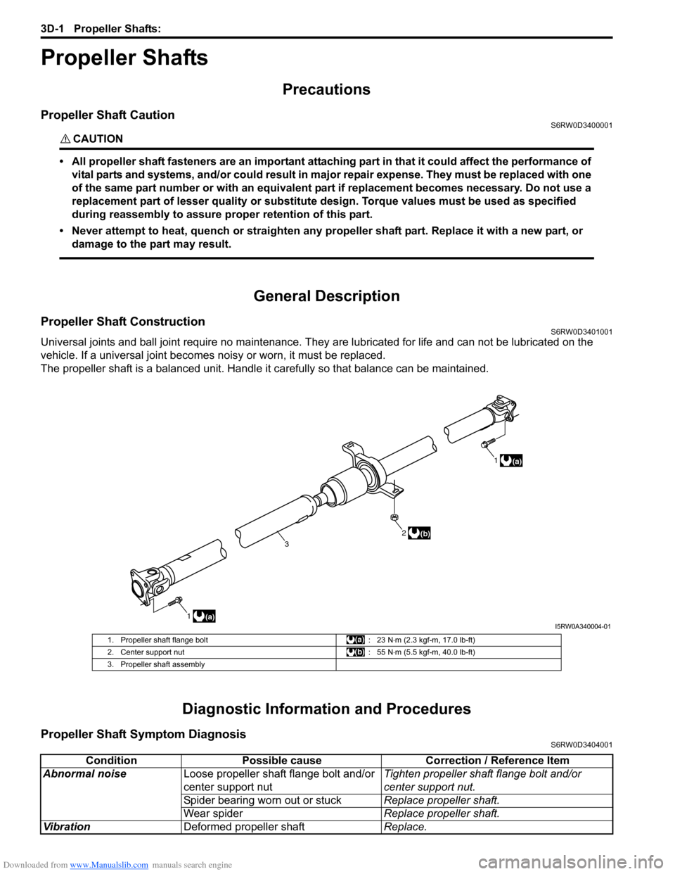
Universal joints and ball joint require no maintenance. They are lubricated for life and can not be lubricated on the
vehicle. If a universal joint becomes noisy or worn, it must be replaced.
The propeller shaft is a balanced unit. Handle it carefully so that balance can be maintained.
Diagnostic Information and Procedures
Propeller Shaft Symptom DiagnosisS6RW0D3404001
1(a)1
(a)
2
3(b)
I5RW0A340004-01
1. Propeller shaft flange bolt : 23 N⋅m (2.3 kgf-m, 17.0 lb-ft)
2. Center support nut : 55 N⋅m (5.5 kgf-m, 40.0 lb-ft)
3. Propeller shaft assembly
Condition Possible cause Correction / Reference Item
Abnormal noiseLoose propeller shaft flange bolt and/or
center support nutTighten propeller shaft flange bolt and/or
center support nut.
Spider bearing worn out or stuckReplace propeller shaft.
Wear spiderReplace propeller shaft.
VibrationDeformed propeller shaftReplace.
Page 589 of 1556

Downloaded from www.Manualslib.com manuals search engine Front Brakes: 4B-2
Front Disc Brake Pad On-Vehicle InspectionS6RW0D4206002
Inspect pad linings (1) periodically according to
maintenance schedule whenever wheels are removed
(for tire rotation or other reason). Take a look through
each end and inspection hole of caliper and check lining
thickness of outside and inside pads.
If lining is worn and its thickness (“a” in figure) is less
than limit, all pads must be replaced at the same time.
Front brake pad thickness “a” (lining thickness)
Standard: 10 mm (0.39 in.)
Limit: 2 mm (0.08 in.)
Front Disc Brake Pad Removal and InstallationS6RW0D4206003
NOTE
When replacing brake pad, replace it on the
right and left.
Removal
1) Hoist vehicle and remove front wheel.
2) Remove caliper pin bolts (1).
3) Remove caliper (1) from caliper carrier (2).
NOTE
Hang removed caliper (1) with a wire hook (4)
or the like so as to prevent brake hose from
bending and twisting excessively or being
pulled.
Don’t operate brake pedal with brake pads
removed.
4) Remove brake pads (3).
5) Remove brake pad spring (1) as show in figure.
Installation
1) Apply small amount of pad grease “a” (included in
spare parts) to pad spring and set brake pad spring
as shown in figure.
2) Set brake pad springs (1), and install brake pads (2)
and shim (4).
NOTE
Install the brake pad with wear indicator (3) to
the vehicle center side of front right brake
pad.
I7RW01420009-01
1
I7RW01420003-01
42
3
1
I7RW01420010-01
1
I7RW01420014-01
"a"
I7RW01420011-01
I7RW01420012-01