2006 SUZUKI SX4 Coolant Level Check
[x] Cancel search: Coolant Level CheckPage 366 of 1556

Downloaded from www.Manualslib.com manuals search engine 1F-1 Engine Cooling System:
Engine
Engine Cooling System
General Description
Cooling System DescriptionS6RW0D1601001
The cooling system consists of the radiator cap, radiator,
coolant reservoir, hoses, water pump, cooling fan and
thermostat. The radiator is of tube-and-fin type.
Coolant DescriptionS6RW0D1601002
WARNING!
• Do not remove radiator cap to check
engine coolant level; check coolant
visually at the see-through coolant
reservoir. Coolant should be added only to
reservoir as necessary.
• As long as there is pressure in the cooling
system, the temperature can be
considerably higher than the boiling
temperature of the solution in the radiator
without causing the solution to boil.
Removal of the radiator cap while engine is
hot and pressure is high will cause the
solution to boil instantaneously and
possibly with explosive force, spewing the
solution over engine, fenders and person
removing cap. If the solution contains
flammable anti-freeze such as alcohol (not
recommended for use at any time), there is
also the possibility of causing a serious
fire.
• Check to make sure that engine coolant
temperature is cold before removing any
part of cooling system.
• Also be sure to disconnect negative cable
from battery terminal before removing any
part.
The coolant recovery system is standard. The coolant in
the radiator expands with heat, and the coolant is
overflowed to the reservoir.
When the system cools down, the coolant is drawn back
into the radiator.
The cooling system has been filled with a quality coolant
that is a 50/50 mixture of water and ethylene glycol
antifreeze.
This 50/50 mixture coolant solution provides freezing
protection to –36 °C (–33 °F).
• Maintain cooling system freeze protection at –36 °C (–
33 °F) to ensure protection against corrosion and loss
of coolant from boiling. This should be done even if
freezing temperatures are not expected.
• Add ethylene glycol base coolant when coolant has to
be added because of coolant loss or to provide added
protection against freezing at temperature lower than
–36 °C (–33 °F).
NOTE
• Alcohol or methanol base coolant or plain
water alone should not be used in cooling
system at any time as damage to cooling
system could occur.
• Coolant must be mixed with demineralized
water or distilled water.
Anti-freeze proportioning table
Coolant capacity
M/T:
• Engine, radiator and heater: 6.8 liters (14.37/11.97
US/lmp pt.)
• Reservoir: 0.7 liters (1.48/1.23 us/lmp pt.)
• Total: 7.5 liters (15.85/13.20 US/lmp pt.)
A/T:
• Engine, radiator and heater: 6.9 liters (14.58/16.63
US/lmp pt.)
• Reservoir: 0.7 liters (1.48/1.23 us/lmp pt.)
• Total: 7.6 liters (16.06/13.38 US/lmp pt.)For M/T
modelFor A/T
model
Freezing
temperature°C–36–36
°F–33–33
Anti-freeze / Anti-
corrosion coolant
concentration%5050
Ratio of compound
to cooling waterltr. 3.75/3.75 3.8/3.8
US pt. 7.92/7.92 8.03/8.03
Imp pt. 6.60/6.60 6.69/6.69
Page 368 of 1556

Downloaded from www.Manualslib.com manuals search engine 1F-3 Engine Cooling System:
Diagnostic Information and Procedures
Engine Cooling Symptom DiagnosisS6RW0D1604001
Condition Possible cause Correction / Reference Item
Engine overheats
(Radiator fan operates)Loose or broken water pump beltAdjust or replace.
Not enough coolantCheck coolant level and add as necessary.
Faulty thermostatReplace.
Faulty water pumpReplace.
Dirty or bent radiator finsClean or remedy.
Coolant leakage on cooling systemRepair.
Clogged radiatorCheck and replace radiator as necessary.
Faulty radiator capReplace.
Dragging brakesAdjust brake.
Slipping clutchReplace.
Poor charge batteryCheck and replace as necessary.
Poor generation generatorCheck and repair.
ECT sensor faultyCheck and replace as necessary.
Radiator fan motor faultyCheck and replace as necessary.
ECM faultyCheck and replace as necessary.
Wiring or grounding faultyRepair as necessary.
Equipped with too much electric load
part(s)Dismount.
Engine overheats
(Radiator fan does not
operate)Fuse blownCheck fuse of relay/fuse box and check for
short circuit to ground.
Radiator cooling fan relay faultyCheck and replace as necessary.
ECT sensor faultyCheck and replace as necessary.
Radiator cooling fan motor faultyCheck and replace as necessary.
Wiring or grounding faultyRepair as necessary.
ECM faultyCheck and replace as necessary.
Page 370 of 1556

Downloaded from www.Manualslib.com manuals search engine 1F-5 Engine Cooling System:
Coolant Level CheckS6RW0D1606002
WARNING!
To help avoid danger of being burned, do not
remove radiator cap while engine and
radiator are still hot. Scalding fluid and steam
can be blown out under pressure if radiator
cap is taken off too soon.
To check level, lift hood and look at “see-through”
coolant reservoir.
It is not necessary to remove radiator cap to check
coolant level.
When engine is cool, check coolant level in reservoir (1).
A normal coolant level should be between FULL mark
(2) and LOW mark (3) on reservoir (1).
If coolant level is below LOW mark (3), remove reservoir
cap (4) and add proper coolant to reservoir to bring
coolant level up to FULL mark (2).
NOTE
If proper quality antifreeze is used, there is
no need to add extra inhibitors or additives
that claim to improve system. They may be
harmful to proper operation of system, and
are unnecessary expense.
Engine Cooling System Inspection and
Cleaning
S6RW0D1606003
WARNING!
To help avoid danger of being burned, do not
remove radiator cap while engine and
radiator are still hot. Scalding fluid and steam
can be blown out under pressure if cap is
taken off too soon.
1) Check cooling system for leakage or damage.
2) Wash radiator cap and filler neck with clean water by
removing radiator cap when engine is cold.
3) Check coolant for proper level and freeze protection.
4) Using a pressure tester (1), check system and
radiator cap (2) for proper pressure holding capacity.
If replacement of cap is required, use a proper cap
for this vehicle.
NOTE
After installing radiator cap to radiator, make
sure that the ear of cap lines is parallel to
radiator.
Cooling system and radiator cap holding
pressure (for inspection)
110 kPa (1.1 kgf/cm2, 15.6 psi)
5) Tighten hose clamps and inspect all hoses. Replace
hoses whenever cracked, swollen or otherwise
deteriorated.
6) Clean frontal area of radiator core.
Cooling System DrainingS6RW0D1606004
WARNING!
To help avoid danger of being burned, do not
remove radiator cap while engine and
radiator are still hot. Scalding fluid and steam
can be blown out under pressure if cap is
taken off too soon.
1) Remove radiator cap.
2) Drain coolant from radiator drain plug (1).
3) After draining coolant, be sure to tighten drain plug
(1) securely.
4
1
2
3
I6RW0B160006-01
I5RH01160001-01
1I4RS0A160003-01
Page 666 of 1556

Downloaded from www.Manualslib.com manuals search engine 5A-18 Automatic Transmission/Transaxle:
Step 2. DTC / Freeze Frame Data Check, Record and
Clearance
First, referring to “DTC Check”, check DTC and pending
DTC. If DTC exists, print or write down DTC and freeze
frame data and then clear malfunction DTC(s) by
referring to “DTC Clearance”. Malfunction DTC indicates
malfunction in the system but it is not possible to know
from it whether the malfunction is occurring now or it
occurred in the past and normal condition has been
restored. In order to know that, check symptom in
question according to Step 5 and then recheck DTC
according to Step 6.
Diagnosing a trouble based on the DTC in this step only
or failure to clear the DTC in this step may result in an
faulty diagnosis, trouble diagnosis of a normal circuit or
difficulty in troubleshooting which is otherwise
unnecessary.
Step 3 and 4. Visual Inspection
As a preliminary step, be sure to perform visual check of
the items that support proper function of the engine and
automatic transaxle referring to “Visual Inspection”.
Step 5. Trouble Symptom Confirmation
Check trouble symptoms based on information obtained
in “Step 1. Customer Complaint Analysis: ” and “Step 2.
DTC / Freeze Frame Data Check, Record and
Clearance: ”.
Also, reconfirm DTC according to “DTC Confirmation
Procedure” described in each DTC flow.
Step 6 and 7. Rechecking and Record of DTC and
Freeze Frame Data
Refer to “DTC Check” for checking procedure.Step 8. A/T Basic Check and A/T Symptom
Diagnosis
Perform basic check of A/T according to “A/T Basic
Check” first. When the end of the flow has been reached,
check the parts of the system suspected as a possible
cause referring to “A/T Symptom Diagnosis” and based
on symptoms appearing on the vehicle (symptoms
obtained through steps of customer complaint analysis,
trouble symptom confirmation and/or A/T basic check)
and repair or replace faulty parts, if any.
Step 9. Troubleshooting for DTC
Based on the DTC indicated in Step 6 / 7 and referring to
“applicable DTC flow”, locate the cause of the trouble,
namely in a sensor, switch, wire harness, connector,
actuator, TCM or other part and repair or replace faulty
parts.
Step 10. Check for Intermittent Problem
Check parts where an intermittent trouble is easy to
occur (e.g. wire harness, connector, etc.), referring to
“Intermittent and Poor Connection Inspection in Section
00” and related circuit of DTC recorded in Step 2.
Step 11. Final Confirmation Test
Confirm that the problem symptom has gone and the
vehicle is free from any abnormal conditions. If what has
been repaired is related to the malfunction DTC, clear
the DTC once and check to ensure that no malfunction
DTC is indicated.
Visual InspectionS6RW0D5104002
Visually check the following parts and systems.
Inspection item Referring
• A/T fluid ----- level, leakage, color “Automatic Transaxle Fluid Level Inspection in
Section 0B”
• A/T fluid hoses ----- disconnection, looseness, deterioration “A/T Fluid Cooler Hoses Replacement”
• Throttle cable (if equipped) ----- play (under warm engine),
installation
• A/T select cable ----- installation “Select Cable Removal and Installation”
• Engine oil ----- level, leakage “Engine Oil and Filter Change in Section 0B”
• Engine coolant ----- level, leakage “Engine Coolant Change in Section 0B”
• Engine mountings ----- play, looseness, damage “Engine Assembly Removal and Installation in
Section 1D”
• Suspension ----- play, looseness “Suspension, Wheels and Tires Symptom
Diagnosis in Section 2A”
• Drive shafts ----- damage “Front Drive Shaft Assembly On-Vehicle Inspection
in Section 3A”
• Battery ----- indicator condition, corrosion of terminal “Battery Inspection in Section 1J”
• Connectors of electric wire harness ----- disconnection, friction “Electronic Shift Control System Components
Location”
• Fuses ----- burning
• Parts ----- installation, damage
• Bolts ----- looseness
• Other parts that can be checked visually
Page 697 of 1556

Downloaded from www.Manualslib.com manuals search engine Automatic Transmission/Transaxle: 5A-49
DTC Confirmation Procedure
WARNING!
• When performing a road test, select a place where there is no traffic or possibility of a traffic
accident and be very careful during testing to avoid occurrence of an accident.
• Road test should be carried out with 2 persons, a driver and a tester, on a level road.
1) Connect scan tool to DLC with ignition switch OFF, if available.
2) Clear DTC in TCM memory and start engine.
3) Increase engine coolant temperature to about 50 °C (122 °F) and more.
4) Start vehicle and increase vehicle speed to about 20 km/h (12 mile/h) for 10 minutes or more.
5) Stop vehicle and check DTC.
DTC Troubleshooting
Step Action Yes No
1Was “A/T System Check” performed?Go to Step 2. Go to “A/T System
Check”.
2Check transmission fluid temperature circuit for open
1) Turn ignition switch OFF.
2) Disconnect TCM connectors from TCM.
3) Check for proper connection to transmission fluid
temperature sensor at terminals “C06-11” and “C06-12”.
4) If OK, check continuity between terminals “C06-11” and
“C06-12” of disconnected harness side TCM connector.
Is continuity indicated?Go to Step 3. “LT GRN” or “ORN”
circuit open.
3Check transmission fluid temperature circuit for IG
short
1) Cool down A/T fluid temperature under ambient
temperature.
2) Connect TCM connectors to TCM with ignition switch
OFF.
3) Turn ignition switch ON.
4) Measure voltage between terminal “C06-11” of TCM
connector and ground.
Is it 4.6 V or more?“LT GRN” circuit shorted
to power circuit.
If circuit is OK, go to
St ep 4 .Intermittent trouble or
faulty TCM.
Check for intermittent
referring to “Intermittent
and Poor Connection
Inspection in Section
00”.
If OK, substitute a
known-good TCM and
recheck.
4Inspect transmission fluid temperature sensor
1) Inspect transmission fluid temperature sensor referring
to “Transmission Fluid Temperature Sensor Inspection”.
Is result satisfactory?Intermittent trouble or
faulty TCM.
Check for intermittent
referring to “Intermittent
and Poor Connection
Inspection in Section
00”.
If OK, substitute a
known-good TCM and
recheck.Replace transmission
fluid temperature
sensor.
Page 1353 of 1556

Downloaded from www.Manualslib.com manuals search engine Instrumentation / Driver Info. / Horn: 9C-1
Body, Cab and Accessories
Instrumentation / Driver Info. / Horn
Precautions
Precautions in Diagnosing Troubles for Combination MeterS6RW0D9300001
Combination meter uses signals (information) from each control module by CAN communication to control
speedometer, tachometer, fuel meter, engine coolant temp meter, warning light and indicator light (other than air bag
warning light, EPS warning light, headlight leveling warning light (if equipped), rear fog light indicator light (if
equipped), high beam indicator light and turn signal indicator light). Therefor, check that no DTC is detected in each
module before performing combination meter symptom diagnosis. If any DTC is detected, correct trouble indicated by
that DTC troubleshooting first.
General Description
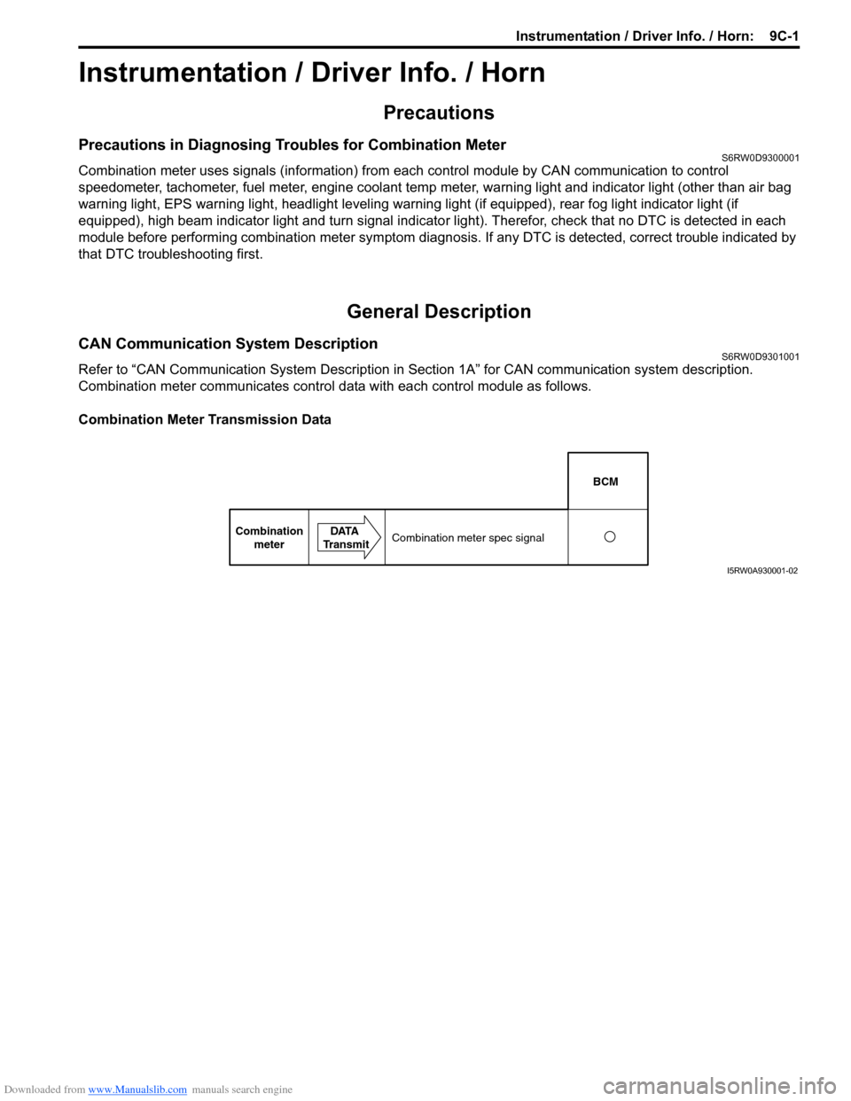
CAN Communication System DescriptionS6RW0D9301001
Refer to “CAN Communication System Description in Section 1A” for CAN communication system description.
Combination meter communicates control data with each control module as follows.
Combination Meter Transmission Data
BCM
Combination
meterDATA
TransmitCombination meter spec signal
I5RW0A930001-02
Page 1358 of 1556

Downloaded from www.Manualslib.com manuals search engine 9C-6 Instrumentation / Driver Info. / Horn:
Diagnostic Information and Procedures
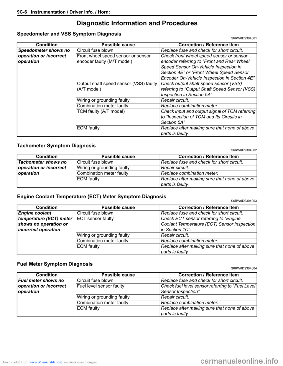
Speedometer and VSS Symptom DiagnosisS6RW0D9304001
Tachometer Symptom DiagnosisS6RW0D9304002
Engine Coolant Temperature (ECT) Meter Symptom DiagnosisS6RW0D9304003
Fuel Meter Symptom DiagnosisS6RW0D9304004
Condition Possible cause Correction / Reference Item
Speedometer shows no
operation or incorrect
operationCircuit fuse blownReplace fuse and check for short circuit.
Front wheel speed sensor or sensor
encoder faulty (M/T model)Check front wheel speed sensor or sensor
encoder referring to “Front and Rear Wheel
Speed Sensor On-Vehicle Inspection in
Section 4E” or “Front Wheel Speed Sensor
Encoder On-Vehicle Inspection in Section 4E”.
Output shaft speed sensor (VSS) faulty
(A/T model)Check output shaft speed sensor (VSS)
referring to “Output Shaft Speed Sensor (VSS)
Inspection in Section 5A”
Wiring or grounding faultyRepair circuit.
Combination meter faulty Replace combination meter.
TCM faulty (A/T model)Check input and output signal of TCM referring
to “Inspection of TCM and Its Circuits in
Section 5A”
ECM faultyReplace after making sure that none of above
parts is faulty.
Condition Possible cause Correction / Reference Item
Tachometer shows no
operation or incorrect
operationCircuit fuse blownReplace fuse and check for short circuit.
Wiring or grounding faultyRepair circuit.
Combination meter faultyReplace combination meter.
ECM faultyReplace after making sure that none of above
parts is faulty.
Condition Possible cause Correction / Reference Item
Engine coolant
temperature (ECT) meter
shows no operation or
incorrect operationCircuit fuse blownReplace fuse and check for short circuit.
ECT sensor faultyCheck ECT sensor referring to “Engine
Coolant Temperature (ECT) Sensor Inspection
in Section 1C”.
Wiring or grounding faultyRepair circuit.
Combination meter faultyReplace combination meter.
ECM faultyReplace after making sure that none of above
parts is faulty.
Condition Possible cause Correction / Reference Item
Fuel meter shows no
operation or incorrect
operationCircuit fuse blownReplace fuse and check for short circuit.
Fuel level sensor faultyCheck fuel level sensor referring to “Fuel Level
Sensor Inspection”.
Wiring or grounding faultyRepair circuit.
Combination meter faultyReplace combination meter.
ECM faultyReplace after making sure that none of above
parts is faulty.
Page 1368 of 1556

Downloaded from www.Manualslib.com manuals search engine 9C-16 Instrumentation / Driver Info. / Horn:
Engine Coolant Temperature (ECT) Sensor
Inspection
S6RW0D9306008
Check engine coolant temperature sensor for resistance,
refer to “Engine Coolant Temperature (ECT) Sensor
Inspection in Section 1C”.
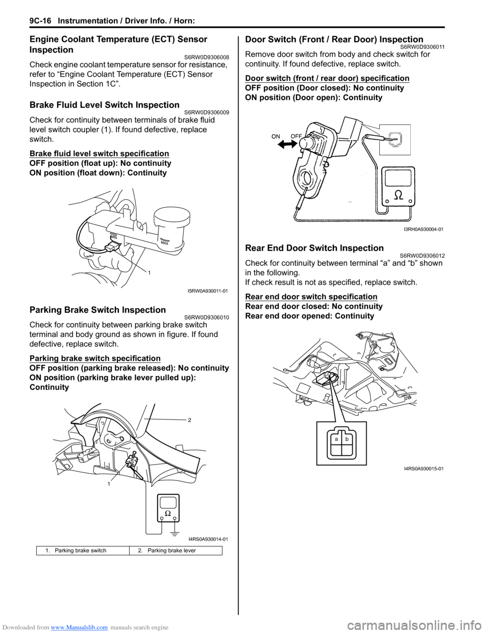
Brake Fluid Level Switch InspectionS6RW0D9306009
Check for continuity between terminals of brake fluid
level switch coupler (1). If found defective, replace
switch.
Brake fluid level switch specification
OFF position (float up): No continuity
ON position (float down): Continuity
Parking Brake Switch InspectionS6RW0D9306010
Check for continuity between parking brake switch
terminal and body ground as shown in figure. If found
defective, replace switch.
Parking brake switch specification
OFF position (parking brake released): No continuity
ON position (parking brake lever pulled up):
Continuity
Door Switch (Front / Rear Door) InspectionS6RW0D9306011
Remove door switch from body and check switch for
continuity. If found defective, replace switch.
Door switch (front / rear door) specification
OFF position (Door closed): No continuity
ON position (Door open): Continuity
Rear End Door Switch InspectionS6RW0D9306012
Check for continuity between terminal “a” and “b” shown
in the following.
If check result is not as specified, replace switch.
Rear end door switch specification
Rear end door closed: No continuity
Rear end door opened: Continuity
1. Parking brake switch 2. Parking brake lever
1
I5RW0A930011-01
12
I4RS0A930014-01
I3RH0A930004-01
a
b
I4RS0A930015-01