Page 1227 of 1556
Downloaded from www.Manualslib.com manuals search engine Wiring Systems: 9A-60
A-3 Ignition System Circuit Diagram (M15A engine, M16A engine)S6RW0D910E004
15A
20E371
C343
2
C1011
3
IG COIL
#1
C102
BLK
BLK/WHTGRN/YEL
BLK/WHT
J/B
ECM
GYGW
20IG COIL
BLK
BLK
IG COIL
#2
E3255
3
GRN/WHT
1
3
2
C015 6
Weld
splice
C312
BLK/WHT
BLK/WHT
I6RW0C910935-01
Page 1228 of 1556
Downloaded from www.Manualslib.com manuals search engine 9A-61 Wiring Systems:
A-3 Ignition System Circuit Diagram (J20A engine)S6RW0D910E039
15A
20E371
C343
2
C1013
1
IG
COIL
#1
C102
BLK
BLK/WHTBLK/WHTBLK/WHTGRN/YEL
BLK/WHT
J/B
ECM
GYGW
20IG COIL
BLKBLK
BLKBLKBLK
IG
COIL
#2
E3255
3
GRN/WHT
4
3
1
2
C0120 21
Weld
splice
C312
BLK/WHT
GB
GRN/BLK
19
G
GRN
18
C103
IG
COIL
#3
3
1
2C104
IG
COIL
#4
3
1
2
BLK/WHT
I6RW0C910A14-01
Page 1229 of 1556
Downloaded from www.Manualslib.com manuals search engine Wiring Systems: 9A-62
A-4 Cooling System Circuit Diagram (M15A engine, M16A engine)S6RW0D910E005
E65
4
5
9
"A-5"
Lg
BR
BW
Relay
Motor
E2223
1
2
1
BLU/REDLT GRNBRN/WHT
GRYBLK/RED
BLK/YELBLK/YEL
30ARDTR
10
E2211
2
15AFI
1
3
4
Main relay
BLK
ECM
Individual circuit
fuse box (No.1)
M
I6RW0C910919-01
Page 1230 of 1556
Downloaded from www.Manualslib.com manuals search engine 9A-63 Wiring Systems:
A-4 Cooling System Circuit Diagram (J20A engine)S6RW0D910E040
E65
4
5
9
LT GRN
"A-5"
Lg
BRBBBW
G
BRN/WHT
BW
BLK/YELBLK/YEL
Relay #1
Motor
E2223
1
243
1
BLU/REDBLU/REDBLU/BLKBLKBLU/RED
BLU/RED
GRY
GRYBLU/WHT
GRNGRN
30ARDTR
10
E2211
2
15AFI
1
3
4
Main relay
BLK
BLK
BLK/RED
ECM
"A-5"
ECM
Individual circuit
fuse box (No.1)
4
5
Relay #2
E2231
35
4
Relay #3
E2241
3
M
I7RW01910924-02
Page 1231 of 1556

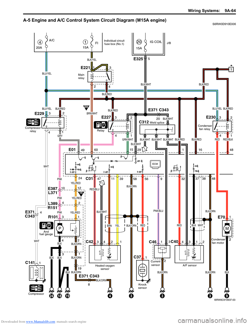
Downloaded from www.Manualslib.com manuals search engine Wiring Systems: 9A-64
A-5 Engine and A/C Control System Circuit Diagram (M15A engine)S6RW0D910E006
YEL/RED
E387
L3711012
L389
R15142
PNKYEL/RED
P
PNKYEL/RED
31
433
31
E371 C343
BLK/ORN
BLK/ORN
BLK/ORN
BLK/ORN
19
8
BLK42
R101
1
And
fuel gauge
Main
relay
1
BLK/WHT
BLK/REDBLU/YEL
C312Weld splice
GRN/WHTBLK/WHT
BLK/WHT
BLK/WHT
IG COILJ/B1
15A
FI
BLK/YEL
E2211
23
415A
20
BRN/WHT
BW
YR
4
20A
A/C
Compressor
relay
E229
Relay
BLU/YEL
BLU/YEL
Compressor
C1411
E3255
E371 C343
20
E371
C3434BLK/WHT
C42C40
Heated oxygen
sensor
RED/BLU
BRN
A/F sensorCondenser
fan motor Condenser
fan relay
BLK
BLK/ORN
BLK/ORN
RED
C01
1
34 2 143 12
4711393237
WHT
3848PNK
ECM
142
3
WHT
WHT
BLK/RED
BLK/REDBLK/WHT
BLK/RED
BLK/RED
BLK/RED
E01496015291
GRY
E22732
4
1
E23032
4
1
YELBLK/ORN
24
BLKBLK
58 56
BLK/REDRED
16 48
182419
Individual circuit
fuse box (No.1)
BLKBLKBLK/ORNBLK/ORN
93
RED/BLK
M
1
2E70
9
PNK/BLU
RED
Knock
sensor
C371
BLK/WHT
Current
sensor
C461
23
I6RW0C910937-03
Page 1235 of 1556

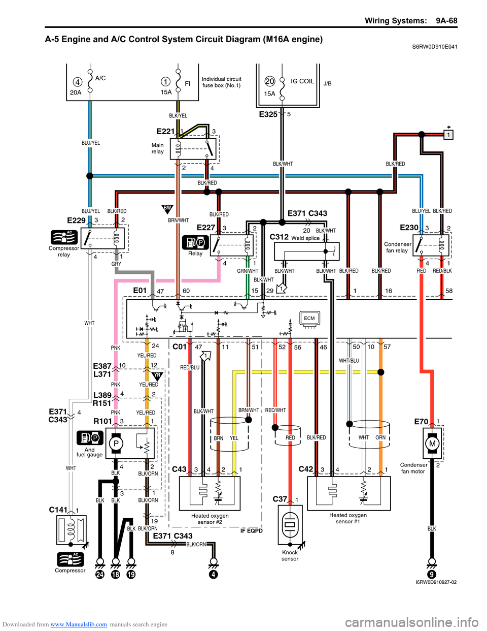
Downloaded from www.Manualslib.com manuals search engine Wiring Systems: 9A-68
A-5 Engine and A/C Control System Circuit Diagram (M16A engine)S6RW0D910E041
YEL/RED
E387
L3711012
L389
R15142
PNKYEL/RED
P
PNKYEL/RED
31
4
31
E371 C343
BLK/ORN
BLK/ORN
BLK/ORN
BLK/ORN
19
8
BLK42
R101
1
And
fuel gauge
Main
relay
1
BLK/WHT
BLK/REDBLU/YEL
C312Weld splice
GRN/WHTBLK/WHT
BLK/WHT
BLK/WHT
IG COILJ/B1
15A
FI
BLK/YEL
E2211
23
415A
20
BRN/WHT
BW
YR
4
20A
A/C
Compressor
relay
E229
Relay
BLU/YEL
BLU/YEL
Compressor
C1411
E3255
E371 C343
20
E371
C3434BLK/WHT
C43C42
Heated oxygen
sensor #2
IF EQPD
RED/BLU
BRN
Heated oxygen
sensor #1Condenser
fan motor Condenser
fan relay
WHT
BRN/WHT
BLK/RED
WHT/BLU
C01
1
34 2 134 2 1
471151
RED/WHT
52461050
ORN
57PNK
ECM
142
3
WHT
WHT
BLK/RED
BLK/REDBLK/WHT
BLK/RED
BLK/RED
BLK/RED
E01476015291
GRY
E22732
4
1
E23032
4
1
YEL
24
BLKBLK
56
BLK/REDRED
16 58
182419
Individual circuit
fuse box (No.1)
BLKBLK
9
RED/BLK
M
1
2E70
RED
Knock
sensor
C371
I6RW0D910927-02
Page 1239 of 1556

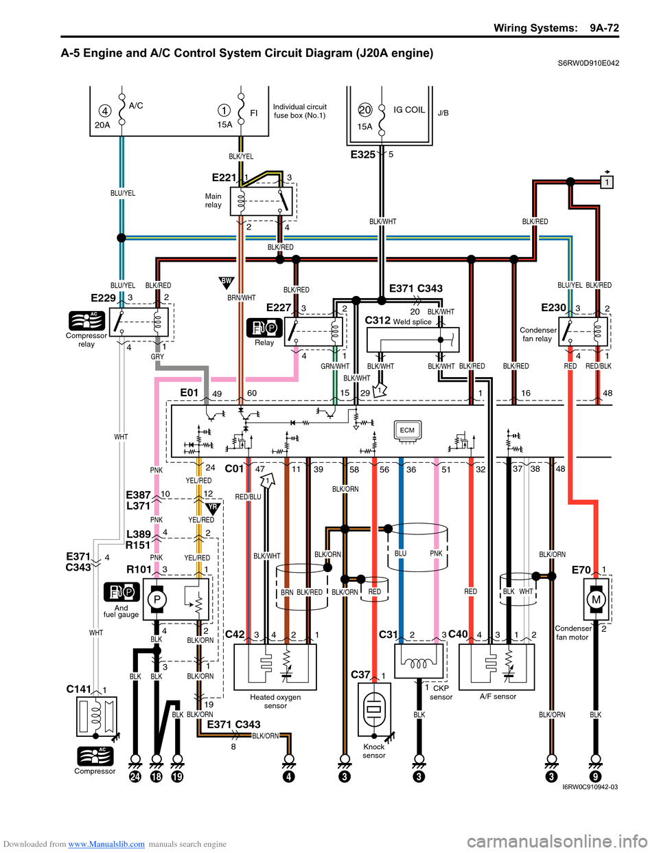
Downloaded from www.Manualslib.com manuals search engine Wiring Systems: 9A-72
A-5 Engine and A/C Control System Circuit Diagram (J20A engine)S6RW0D910E042
YEL/RED
E387
L3711012
L389
R15142
PNKYEL/RED
P
PNKYEL/RED
31
433
31
E371 C343
BLK/ORN
BLK/ORN
BLK/ORN
BLK/ORN
19
8
BLK42
R101
1
And
fuel gauge
Main
relay
1
BLK/WHT
BLK/REDBLU/YEL
C312Weld splice
GRN/WHTBLK/WHT
BLK/WHT
BLK/WHT
IG COILJ/B1
15A
FI
BLK/YEL
E2211
23
415A
20
BRN/WHT
BW
YR
4
20A
A/C
Compressor
relay
E229
Relay
BLU/YEL
BLU/YEL
Compressor
C1411
C312
13
E3255
E371 C343
20
E371
C3434BLK/WHT
C42C40
Heated oxygen
sensor
RED/BLU
BRN
A/F sensor CKP
sensorCondenser
fan motor Condenser
fan relay
BLK
BLK/ORNBLK/ORN
BLK/ORN
RED
C01
1
34 2 143 12
4711393237
WHT
3848PNK
ECM
142
3
WHT
WHT
BLK/RED
BLK/REDBLK/WHT
BLK/RED
BLK/RED
BLK/RED
E01496015291
GRY
E22732
4
1
E23032
4
1
BLK/REDBLK/ORN
24
BLKBLK
58 56
BLK/REDRED
16 48
182419
Individual circuit
fuse box (No.1)
BLKBLKBLK/ORNBLK
93
RED/BLK
M
1
2E70
3651
BLUPNK
RED
Knock
sensor
C371
I6RW0C910942-03
Page 1243 of 1556
Downloaded from www.Manualslib.com manuals search engine Wiring Systems: 9A-76
A-6 A/T Control System Circuit DiagramS6RW0D910E007
GRN/RED
Shift
lock
relay
E241
GRN/RED
C0720 8 7 19 18
E371 C343GRN/YEL
Back-up light
14
RED
"D-8"
Brake light
switch
"D-7"
R
GW
Transaxle
range sensor
TCM
L101
4
A/T select
switch A/T
shift lock
solenoidA/T shift
lever assy
BLK/ORN
16
OFF
ON
RED
1
RED
PNK/BLKRED
GRN/ORNLT GRN/BLK
C166
P
R
N
D2L
PNK/BLK
5
4
E371 C343
17
PNK/BLK
BLKBLK
63
BLK/ORN
1720
BLK
14
BLKBLK
79
L348
J/C
E387
L371C343
E3711320
BCM
BCM
DLC
G21174
BLK
BLK
11
J/C
G309
4
G334
E38219
E371
C3438
BLK/ORNBLK/ORN
5
239
GRN
RED/BLK
E371
C34313
E32514RED/BLK
GRN/WHT
10ABACK21
15ADOME37
BLK
3
1
J/B
1
A
AB
B
J/C
G308A
A
BLU
BLU
BLU
BLU
R
15YEL
YEL
YEL
12
E382
G33412
GR
PB
B
WHTRED
RW"A-8"
14
6
BLK/ORN
G2715
B
B
J/C
Taiwan
IF EQPD
BLU
Except Taiwan
G308
9E04
5G04
WHT/RED
WHT/RED
16
(CAN)
M15A engine, M16A engine
J20A engine A
8
4AB4
1AB5
9AB2
6AB1
3AB7
11AB
3
10AB
B
I6RW0C910948-01