Page 1205 of 1556
Downloaded from www.Manualslib.com manuals search engine Wiring Systems: 9A-38
Individual Circuit Fuse Box No. 2 (In J/B (Except Taiwan))S6RW0D910D009
19
25
20
26
34
21
27
35
22
28
36
23
29
37
24
30
38
31
39
32
40
33
41
42USE THE DESINGNATED FUSES AND RELAYS ONLY.
I7RW01910912-02
No. Fuse Description on the cover Protected circuit
15 A RR WIPRear wiper motor
Rear washer motor
15 A IG COILA/F sensor
Current sensor
ECM
Fuel pump relay
Generator
Heated oxygen sensor #1
Heated oxygen sensor #2
VSS
ICM
IG coil #1
IG coil #2
IG coil #3
IG coil #4
10 A BACKBack-up light switch
Fresh / Recircle actuator
Mode control switch
Auto A/C unit
4WD control module
KLS ECM
Transaxle range sensor
Headlight beam leveling switch
Headlight beam leveling actuator (R)
Headlight beam leveling actuator (L)
10 A MTRCOMB meter
Flasher relay
15 A ACCBCM
Power mirror switch
ACC socket
15 A ACC 2Rear ACC socket
Audio
Multi information display
KLS ECM
Page 1206 of 1556

Downloaded from www.Manualslib.com manuals search engine 9A-39 Wiring Systems:
30 A WIPCOMB switch
Windshield washer motor
Windshield wiper motor
Rear wiper relay
DRL controller
10 A IG1 SIGPower steering control module
A/T relay
Brake light switch
15 A A/B A/B SDM
10 A ABSABS control module
G sensor
10 A TAILCOMB switch
DRL controller
15 A STOP Brake light switch
20 A D/L BCM
15 A 4WD 4WD control module
10 A ST SIG Starting motor relay
15 A S/HSeat heater switch (Driver side)
Seat heater switch (Passenger side)
10 A IG2 SIG Blower fan relay
15 A RR FOG COMB switch
15 A DOMEAudio
BCM
COMB meter
DLC
ECM
Interior light
ICM
TCM
Rear interior light
Luggage compartment light
Main switch (Key switch)
Multi information display
KLS ECM
30 A RR DEFRear defogger relay
Mirror motor (R)
Mirror motor (L)
15 A HORN-HAZHorn relay
Flasher relay
BLANK BLANK BLANK
BLANK BLANK BLANK
30 A P/WPower window main switch
Front power window sub switch
Rear power window sub switch (R)
Rear power window sub switch (L) No. Fuse Description on the cover Protected circuit
Page 1207 of 1556
Downloaded from www.Manualslib.com manuals search engine Wiring Systems: 9A-40
Individual Circuit Fuse Box No. 2 (In J/B (Taiwan))S6RW0D910D005
19
25
20
26
34
21
27
35
22
28
36
23
29
37
24
30
38
31
39
32
40
33
41
42USE THE DESINGNATED FUSES AND RELAYS ONLY.
I7RW01910912-02
No. Fuse Description on the cover Protected circuit
15 A RR WIPRear wiper motor
Rear washer motor
15 A IG COILBCM
A/F
ECM
Fuel pump relay
Generator
Heated oxygen sensor #1
Heated oxygen sensor #2
VSS
ICM
IG coil #1
IG coil #2
IG coil #3
IG coil #4
10 A BACKBack-up light switch
Fresh / Recircle actuator
Mode control switch
Auto A/C unit
KLS ECM
Transaxle range sensor
10 A MTRCOMB meter
Flasher relay
15 A ACCBCM
Power mirror switch
ACC socket
15 A ACC 2Rear ACC socket
Audio
Multi information display
KLS ECM
30 A WIPCOMB switch
Windshield washer motor
Windshield wiper motor
Rear wiper relay
10 A IG1 SIGPower steering control module
A/T relay
15 A A/B A/B SDM
Page 1208 of 1556
Downloaded from www.Manualslib.com manuals search engine 9A-41 Wiring Systems:
10 A ABSABS control module
G sensor
BLANK BLANK BLANK
15 A STOP Brake light switch
20 A D/L BCM
BLANK BLANK BLANK
10 A ST SIG Starting motor relay
BLANK BLANK BLANK
10 A IG2 SIG Blower fan relay
10 A TAIL Tail light relay
15 A DOMEAudio
BCM
COMB meter
DLC
ECM
Interior light
ICM
TCM
Rear interior light
Luggage compartment light
Main switch (Key switch)
Multi information display
KLS ECM
30 A RR DEFRear defogger relay
Mirror motor (R)
Mirror motor (L)
15 A HORN-HAZHorn relay
Flasher relay
BLANK BLANK BLANK
BLANK BLANK BLANK
30 A P/WPower window main switch
Front power window sub switch
Rear power window sub switch (R)
Rear power window sub switch (L) No. Fuse Description on the cover Protected circuit
Page 1224 of 1556

Downloaded from www.Manualslib.com manuals search engine 9A-57 Wiring Systems:
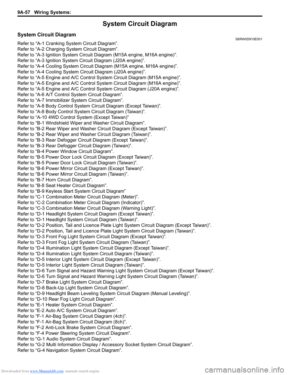
System Circuit Diagram
System Circuit DiagramS6RW0D910E001
Refer to “A-1 Cranking System Circuit Diagram”.
Refer to “A-2 Charging System Circuit Diagram”.
Refer to “A-3 Ignition System Circuit Diagram (M15A engine, M16A engine)”.
Refer to “A-3 Ignition System Circuit Diagram (J20A engine)”.
Refer to “A-4 Cooling System Circuit Diagram (M15A engine, M16A engine)”.
Refer to “A-4 Cooling System Circuit Diagram (J20A engine)”.
Refer to “A-5 Engine and A/C Control System Circuit Diagram (M15A engine)”.
Refer to “A-5 Engine and A/C Control System Circuit Diagram (M16A engine)”.
Refer to “A-5 Engine and A/C Control System Circuit Diagram (J20A engine)”.
Refer to “A-6 A/T Control System Circuit Diagram”.
Refer to “A-7 Immobilizer System Circuit Diagram”.
Refer to “A-8 Body Control System Circuit Diagram (Except Taiwan)”.
Refer to “A-8 Body Control System Circuit Diagram (Taiwan)”.
Refer to “A-10 4WD Control System (Except Taiwan)”
Refer to “B-1 Windshield Wiper and Washer Circuit Diagram”.
Refer to “B-2 Rear Wiper and Washer Circuit Diagram (Except Taiwan)”.
Refer to “B-2 Rear Wiper and Washer Circuit Diagram (Taiwan)”.
Refer to “B-3 Rear Defogger Circuit Diagram (Except Taiwan)”.
Refer to “B-3 Rear Defogger Circuit Diagram (Taiwan)”.
Refer to “B-4 Power Window Circuit Diagram”.
Refer to “B-5 Power Door Lock Circuit Diagram (Except Taiwan)”.
Refer to “B-5 Power Door Lock Circuit Diagram (Taiwan)”.
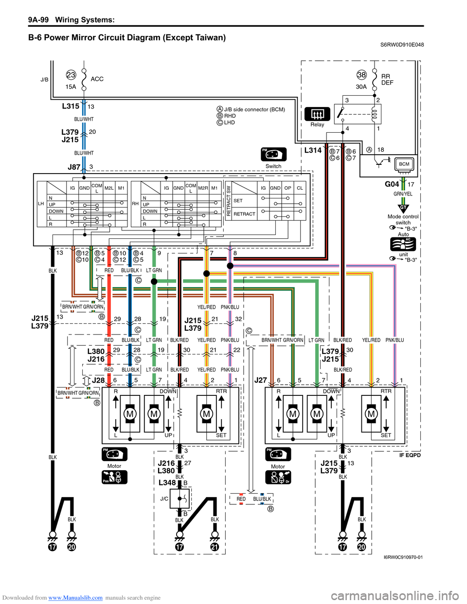
Refer to “B-6 Power Mirror Circuit Diagram (Except Taiwan)”.
Refer to “B-6 Power Mirror Circuit Diagram (Taiwan)”.
Refer to “B-7 Horn Circuit Diagram”.
Refer to “B-8 Seat Heater Circuit Diagram”.
Refer to “B-9 Keyless Start System Circuit Diagram”
Refer to “C-1 Combination Meter Circuit Diagram (Meter)”.
Refer to “C-2 Combination Meter Circuit Diagram (Indicator)”.
Refer to “C-3 Combination Meter Circuit Diagram (Warning Light)”.
Refer to “D-1 Headlight System Circuit Diagram (Except Taiwan)”.
Refer to “D-1 Headlight System Circuit Diagram (Taiwan)”.
Refer to “D-2 Position, Tail and Licence Plate Light System Circuit Diagram (Except Taiwan)”.
Refer to “D-2 Position, Tail and Licence Plate Light System Circuit Diagram (Taiwan)”.
Refer to “D-3 Front Fog Light System Circuit Diagram (Except Taiwan)”.
Refer to “D-3 Front Fog Light System Circuit Diagram (Taiwan)”.
Refer to “D-4 Illumination Light System Circuit Diagram (Except Taiwan)”.
Refer to “D-4 Illumination Light System Circuit Diagram (Taiwan)”.
Refer to “D-5 Interior Light System Circuit Diagram (Except Taiwan)”.
Refer to “D-5 Interior Light System Circuit Diagram (Taiwan)”.
Refer to “D-6 Turn Signal and Hazard Warning Light System Circuit Diagram (Except Taiwan)”.
Refer to “D-6 Turn Signal and Hazard Warning Light System Circuit Diagram (Taiwan)”.
Refer to “D-7 Brake Light System Circuit Diagram”.
Refer to “D-8 Back-Up Light System Circuit Diagram”.
Refer to “D-9 Headlight Beam Leveling System Circuit Diagram (Manual Leveling)”.
Refer to “D-10 Rear Fog Light Circuit Diagram”.
Refer to “E-1 Heater System Circuit Diagram”.
Refer to “E-2 Auto A/C System Circuit Diagram”.
Refer to “F-1 Air-Bag System Circuit Diagram (4ch)”.
Refer to “F-1 Air-Bag System Circuit Diagram (8ch)”.
Refer to “F-2 Anti-Lock Brake System Circuit Diagram”.
Refer to “F-4 Power Steering System Circuit Diagram”.
Refer to “G-1 Audio System Circuit Diagram”.
Refer to “G-2 Multi Information Display / Accessory Socket System Circuit Diagram”.
Refer to “G-4 Navigation System Circuit Diagram”.
Page 1266 of 1556

Downloaded from www.Manualslib.com manuals search engine 9A-99 Wiring Systems:
B-6 Power Mirror Circuit Diagram (Except Taiwan)S6RW0D910E048
13
13
5
9
R
L
3 20
77
J87 L315
L379
J215
6J27
J28
13J215
L379J215
L379
BLK
BLK
17172017
Switch
MotorIF EQPD
MM
DOWN
UP
5
R
L
6
Motor
MMM
DOWN
SET RTR
UP
M
SET RTR
4
3
27
B
B
421
BLU/WHT
BLU/WHT
ACC
15A23RR
DEF
30A38
19 28 2930
19 28 29
L380
J216L379
J21530
LT GRNBLK/RED
LT GRN
GRN/YEL
LT GRN
7
2
21
21
YEL/RED
YEL/RED
8
1
22
32
PNK/BLU
PNK/BLU
YEL/REDPNK/BLU
YEL/REDPNK/BLUBLK/RED
BLK/RED
BLK/REDLT GRN
BLU/BLKRED
BLU/BLKRED
BLU/BLKRED
BRN/WHTGRN/ORN
BLKBLK
BLKBLK
BLK
20
BLK
21
BLKBLK
N
UP
DOWN
L
R LHIG GND M2L M1COM
LN
UP
DOWN
L
R RHIG GND M2R M1COM
LSET
RETRACT
RETRACT SW
IG GND OP CL
J216
L38013J215
L379
4 32
1Relay
G0417
L314
J/B
BCM
GY
"B-3"
"B-3"
Mode control
switch
Auto
unit
3
J/C
L348
J/B side connector (BCM)
RHD
LHD AB
C
C
GRN/ORNBRN/WHT
B
GRN/ORNBRN/WHT
B
BLU/BLKRED
B
C
C
C
7
6BC
4
5BC10
12BC5
4BC12
10BC
6
7BC
18 A
I6RW0C910970-01
Page 1267 of 1556
Downloaded from www.Manualslib.com manuals search engine Wiring Systems: 9A-100
B-6 Power Mirror Circuit Diagram (Taiwan)S6RW0D910E016
13 10 4 12 5
13
5
9
R
L
3 20
77
J87 L315
L379
J215
6J27
J28
13J215
L379J215
L379
BLK
BLK
17172017
Switch
Motor
MM
DOWN
UP
5
R
L
6
Motor
MMM
DOWN
SET RTR
UP
M
SET RTR
4
3
27
B
B
421
BLU/WHT
BLU/WHT
ACC
15A23RR
DEF
30A38
19 28 2930
19 28 29
L380
J216L379
J21530
LT GRNBLK/RED
LT GRN
GRN/YEL
BRN
LT GRN
7
2
21
21
YEL/RED
YEL/RED
8
1
22
32
PNK/BLU
PNK/BLU
YEL/REDPNK/BLU
YEL/REDPNK/BLUBLK/RED
BLK/RED
BLK/REDLT GRN
BLU/BLKRED
BLU/BLKRED
BLU/BLKRED
BRN/WHTGRN/ORN
BLKBLK
BLKBLK
BLK
20
BLK
21
BLKBLK
N
UP
DOWN
L
R LHIG GND M2L M1COM
LN
UP
DOWN
L
R RHIG GND M2R M1COM
LSET
RETRACT
RETRACT SW
IG GND OP CL
14G05
J216
L38013J215
L379
4 32
1Relay
G0420
7L3146G27214
J/B
BCM
GY
"B-3"
"B-3"
Mode control
switch
Auto
unit
3
J/C
L348
I7RW01910944-05
Page 1386 of 1556

Downloaded from www.Manualslib.com manuals search engine 9E-1 Glass / Windows / Mirrors:
Body, Cab and Accessories
Glass / Windows / Mirrors
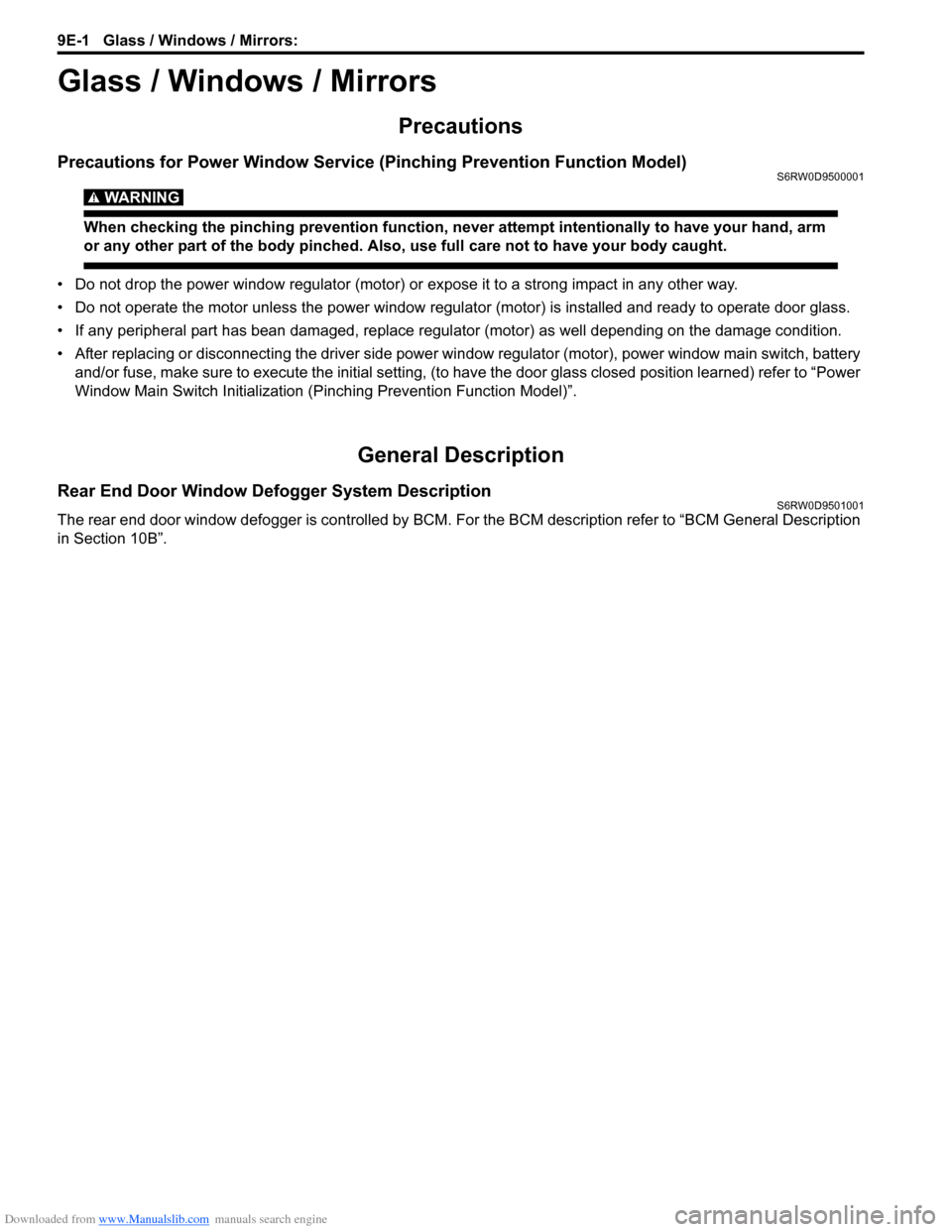
Precautions
Precautions for Power Window Service (Pinching Prevention Function Model)S6RW0D9500001
WARNING!
When checking the pinching prevention function, never attempt intentionally to have your hand, arm
or any other part of the body pinched. Also, use full care not to have your body caught.
• Do not drop the power window regulator (motor) or expose it to a strong impact in any other way.
• Do not operate the motor unless the power window regulator (motor) is installed and ready to operate door glass.
• If any peripheral part has bean damaged, replace regulator (motor) as well depending on the damage condition.
• After replacing or disconnecting the driver side power window regulator (motor), power window main switch, battery
and/or fuse, make sure to execute the initial setting, (to have the door glass closed position learned) refer to “Power
Window Main Switch Initialization (Pinching Prevention Function Model)”.
General Description
Rear End Door Window Defogger System DescriptionS6RW0D9501001
The rear end door window defogger is controlled by BCM. For the BCM description refer to “BCM General Description
in Section 10B”.