Page 1205 of 1556
Downloaded from www.Manualslib.com manuals search engine Wiring Systems: 9A-38
Individual Circuit Fuse Box No. 2 (In J/B (Except Taiwan))S6RW0D910D009
19
25
20
26
34
21
27
35
22
28
36
23
29
37
24
30
38
31
39
32
40
33
41
42USE THE DESINGNATED FUSES AND RELAYS ONLY.
I7RW01910912-02
No. Fuse Description on the cover Protected circuit
15 A RR WIPRear wiper motor
Rear washer motor
15 A IG COILA/F sensor
Current sensor
ECM
Fuel pump relay
Generator
Heated oxygen sensor #1
Heated oxygen sensor #2
VSS
ICM
IG coil #1
IG coil #2
IG coil #3
IG coil #4
10 A BACKBack-up light switch
Fresh / Recircle actuator
Mode control switch
Auto A/C unit
4WD control module
KLS ECM
Transaxle range sensor
Headlight beam leveling switch
Headlight beam leveling actuator (R)
Headlight beam leveling actuator (L)
10 A MTRCOMB meter
Flasher relay
15 A ACCBCM
Power mirror switch
ACC socket
15 A ACC 2Rear ACC socket
Audio
Multi information display
KLS ECM
Page 1207 of 1556
Downloaded from www.Manualslib.com manuals search engine Wiring Systems: 9A-40
Individual Circuit Fuse Box No. 2 (In J/B (Taiwan))S6RW0D910D005
19
25
20
26
34
21
27
35
22
28
36
23
29
37
24
30
38
31
39
32
40
33
41
42USE THE DESINGNATED FUSES AND RELAYS ONLY.
I7RW01910912-02
No. Fuse Description on the cover Protected circuit
15 A RR WIPRear wiper motor
Rear washer motor
15 A IG COILBCM
A/F
ECM
Fuel pump relay
Generator
Heated oxygen sensor #1
Heated oxygen sensor #2
VSS
ICM
IG coil #1
IG coil #2
IG coil #3
IG coil #4
10 A BACKBack-up light switch
Fresh / Recircle actuator
Mode control switch
Auto A/C unit
KLS ECM
Transaxle range sensor
10 A MTRCOMB meter
Flasher relay
15 A ACCBCM
Power mirror switch
ACC socket
15 A ACC 2Rear ACC socket
Audio
Multi information display
KLS ECM
30 A WIPCOMB switch
Windshield washer motor
Windshield wiper motor
Rear wiper relay
10 A IG1 SIGPower steering control module
A/T relay
15 A A/B A/B SDM
Page 1248 of 1556
Downloaded from www.Manualslib.com manuals search engine 9A-81 Wiring Systems:
1817
GRN/WHTGRN/YEL
"E-1"
"E-2"
Mode control
switch
Auto
unit
G04 L01
"B-5""B-5""B-5""B-5"
11
9
L346
10
B E E
Rear
GRN
GRN
RED/BLU
GRNRED/BLU
B
L347
RED/BLUGRNRED/BLU
GRN
RED/BLU
B 1
10
B E
GRN/REDRED/BLU
BLU/YELGRN
Rear end
4
WHT/RED
Rear end
door lock
switch
3 D
D F
"D-5"
BLK/YEL
L01
Diode #2
BY
GWGYWR
G04
L31515
PPL
PPL
P
PPL
P
PPL
P
BYGRRBGGRBGRBGRB
"B-5"
Audio J/B
"G-1"Navigation
"G-4"
SolenoidMotor (R)
"B-5"
Rear
Motor (L)
J/CIF EQPDJ/C
"B-3"
Mode control
switch
BCM
BLK/YEL
BY
BLK/YEL
"D-5"Solenoid
Rear end
J/C
J/C
L346
L347
"B-3"
Auto
unit
G352
L40221211
P/S
Cont.M
"F-4"
24A23
J/B side connector (BCM) A
I6RW0C910953-02
Page 1252 of 1556
Downloaded from www.Manualslib.com manuals search engine 9A-85 Wiring Systems:
620
GRN/WHTGRN/YEL
"E-1"
"E-2"
Mode control
switch
Auto
unit
G05 G04 G05 G06
"B-5""B-5""B-5""B-5"
72
L346
3
B E E
Rear
GRN
GRN
RED/BLU
GRNRED/BLU
B
L347
RED/BLUGRNRED/BLU
GRN
RED/BLU
B 9
8
B E
GRN/REDRED/BLUBLU/YEL
BLU/YELGRN
Rear end
30
WHT/RED
Rear end
door lock
switch
29 D
D F
"D-5"
BLK/YEL
BLK/YEL
G05
Diode #2 Relay
BY
GWGYWR
G0422
PPL
PPL
P
PPL
P
BYGRRBGGRBGRBGRB
"B-5"
Audio
"G-1"
SolenoidMotor (R)
"B-5"
Rear
Motor (L)
J/CJ/C
"B-3"
Mode control
switch
BCM
BLK/YEL
BY
BLK/YEL
"D-5"Solenoid
Rear end
J/C
J/C
L346
L347
"B-3"
Auto
unit
L376
G34316
17
"D-3"
BLK
BLK
B
E381
G33313
G352
L4023G352
L40221211
P/S
Cont.M
"F-4"
I6RW0C910957-01
Page 1253 of 1556
Downloaded from www.Manualslib.com manuals search engine Wiring Systems: 9A-86
19G041
B
BG06
11
J/C
G309
A
A
J/C
G306
BLK
14
BLK
"F-1"
YELBLK
A/B
SDM
Switch
Auto
unit"D-6"
Model control
switch
"E-1""E-2"
A/T shift
lever
"D-4"
Switch
"D-3"
Audio
"G-1"
Y
G0434G05
WHT
W
14
BLK/YEL
BLK/YEL
BY
C
C
J/C
G306
14
BLK/YEL
C
C
J/C
G308
YEL
BLK
BY
"A-2" Generator
10
WHT/BLU
WB
5
YEL
Y
GRY
16G04
G
"G-2" Multi
information
display
BCM
Auto
unit
"E-2"
Switch
"D-6"
I6RW0C910958-01
Page 1282 of 1556

Downloaded from www.Manualslib.com manuals search engine 9A-115 Wiring Systems:
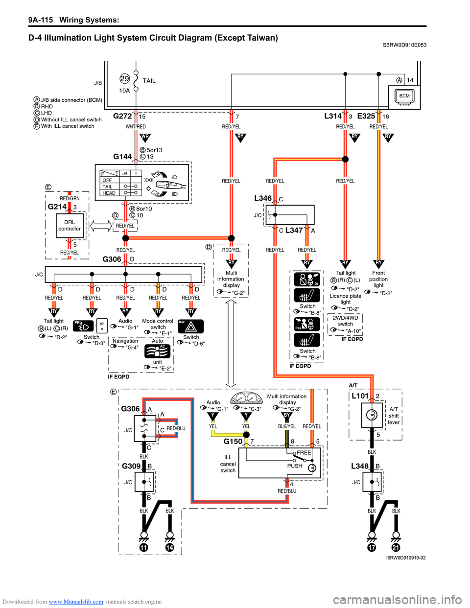
D-4 Illumination Light System Circuit Diagram (Except Taiwan)S6RW0D910E053
BLKBLK
BLK
RED/BLU
RED/BLU
11
J/C
J/C
B
B
14
G309
A
A
C
CG306
BLK/YELRED/YEL
BY
YELYEL
YY
Multi information
display
"G-2"Audio
"G-1""C-3"
ILL
cancel
switch
G150758
4
PUSHFREE
WHT/RED
10ATAIL
29J/B
15G272
G144
1721
RED/YELRED/YELRED/YEL
RED/YELRED/YEL
L3143
BLKBLK
BLK
"D-3"
A/T
RY
Switch
J/C
G306
RED/YEL
RY
RED/YEL
Switch
Auto
unit
IF EQPDIF EQPDIF EQPD
RY
RED/YEL
Mode control
switch
"E-1"Tail light
(L)
"D-2"
"E-2"
"D-6"Switch"B-8"
Switch"B-8"
OFF
TAIL
HEAD+BT T
P
7
RY
RED/YEL
Audio
"G-1"
Navigation
"G-4"
D
D
D D D
RY
RED/YEL
D
RED/YEL
Multi
information
display
"G-2"
RED/YEL
RYRYRY
RYRYWR
Tail light
"D-2"Front
position
light
"D-2"
Licence plate
light
"D-2"
2WD/4WD
switch
"A-10"
RED/YELRED/YEL
RED/YEL
E32516
RY
RY
J/C
B
BL348
J/C
C
C
A
L346
L347
A/T
shift
lever
L1012
5
5or13
13BC
8or10
10BC
J/B side connector (BCM)
RHD
LHD
Without ILL cancel switch
With ILL cancel switch ABCDE
B(R)
C
(R)
B(L)
C
BCM
14A
RED/YEL
D
D
E
DRL
controller
G2143
5
RED/YEL
RED/GRN
E
I6RW0D910919-02
Page 1283 of 1556
Downloaded from www.Manualslib.com manuals search engine Wiring Systems: 9A-116
D-4 Illumination Light System Circuit Diagram (Taiwan)S6RW0D910E025
BLU/WHT
RED/YEL
10ATAIL
36
J/B
12G272
10
G14413
131721
RED/YELRED/YEL
RED/YELRED/YELRED/YEL
L3143
BLKBLK
BLKBLK
"D-3"
A/T
RY
Switch
J/C
G306
RED/YEL
RY
RED/YEL
Switch
Auto
unit
RY
RED/YEL
Mode control
switch
"E-1"Tail light
(R)
"D-2"
"E-2"
"D-6"
OFF
TAIL
HEAD+BT T
P
187
RY
RED/YEL
Audio
"G-1"
D
D
D D D
RY
RED/YEL
D
RED/YEL
Multi
information
display
"G-2"
RED/YEL
RYRY
RYRY
RY
Tail light (L)
"D-2"Front
position
light
"D-2"
Licence plate
light
"D-2"
RED/YEL
RED/YEL
E32516
RY
RY
J/C
B
BL348
J/C
C
CL346
A/T
shift
lever
L1012
5
2 1
3
4
Tail light
relay
11
G05
G0412
BCM
I6RW0C910985-01
Page 1365 of 1556

Downloaded from www.Manualslib.com manuals search engine Instrumentation / Driver Info. / Horn: 9C-13
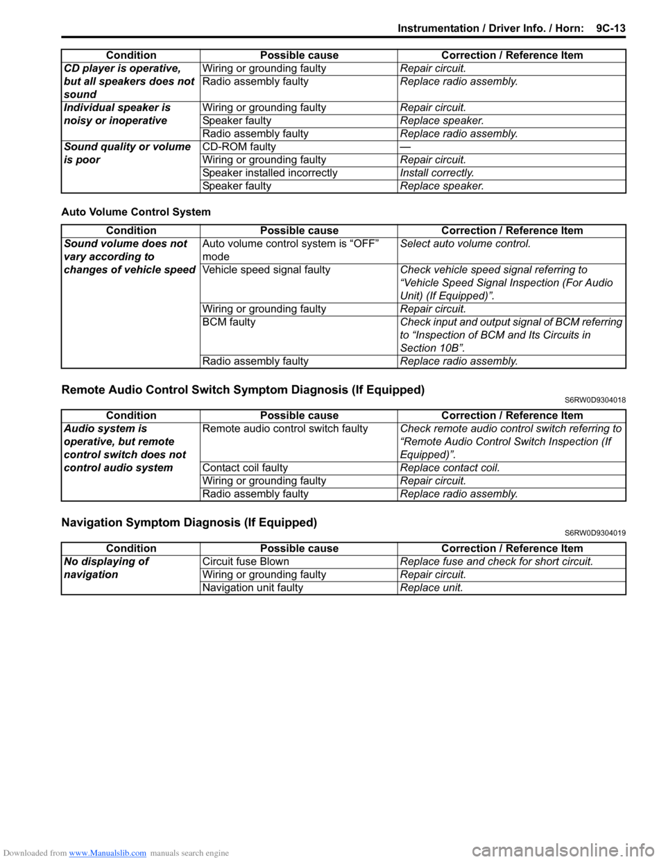
Auto Volume Control System
Remote Audio Control Switch Symptom Diagnosis (If Equipped)S6RW0D9304018
Navigation Symptom Diagnosis (If Equipped)S6RW0D9304019
CD player is operative,
but all speakers does not
soundWiring or grounding faultyRepair circuit.
Radio assembly faultyReplace radio assembly.
Individual speaker is
noisy or inoperativeWiring or grounding faultyRepair circuit.
Speaker faultyReplace speaker.
Radio assembly faultyReplace radio assembly.
Sound quality or volume
is poorCD-ROM faulty—
Wiring or grounding faultyRepair circuit.
Speaker installed incorrectlyInstall correctly.
Speaker faultyReplace speaker. Condition Possible cause Correction / Reference Item
Condition Possible cause Correction / Reference Item
Sound volume does not
vary according to
changes of vehicle speedAuto volume control system is “OFF”
modeSelect auto volume control.
Vehicle speed signal faultyCheck vehicle speed signal referring to
“Vehicle Speed Signal Inspection (For Audio
Unit) (If Equipped)”.
Wiring or grounding faultyRepair circuit.
BCM faultyCheck input and output signal of BCM referring
to “Inspection of BCM and Its Circuits in
Section 10B”.
Radio assembly faultyReplace radio assembly.
Condition Possible cause Correction / Reference Item
Audio system is
operative, but remote
control switch does not
control audio systemRemote audio control switch faultyCheck remote audio control switch referring to
“Remote Audio Control Switch Inspection (If
Equipped)”.
Contact coil faultyReplace contact coil.
Wiring or grounding faultyRepair circuit.
Radio assembly faultyReplace radio assembly.
Condition Possible cause Correction / Reference Item
No displaying of
navigationCircuit fuse BlownReplace fuse and check for short circuit.
Wiring or grounding faultyRepair circuit.
Navigation unit faultyReplace unit.