2006 SUZUKI SX4 audio
[x] Cancel search: audioPage 1128 of 1556
Downloaded from www.Manualslib.com manuals search engine 8B-89 Air Bag System:
Inspection of Intermittent and Poor
Connections
S6RW0D8204047
Most intermittents are caused by faulty electrical
connections or wiring. When a check for proper
connection is requested in a diagnostic flow, perform
careful check of suspect circuits.
If any abnormality is found, repair or replace as a wire
harness assembly.
• Poor mating of connector halves, or terminals not fully
seated in the connector body (backed out).• Dirt or corrosion on the terminals. The terminals must
be clean and free of any foreign material which could
impede proper terminal contact.
However, cleaning the terminal with a sand paper or
the like is prohibited.
• Damaged connector body, exposing the terminals to
moisture and dirt, as well as not maintaining proper
terminal orientation with the component or mating
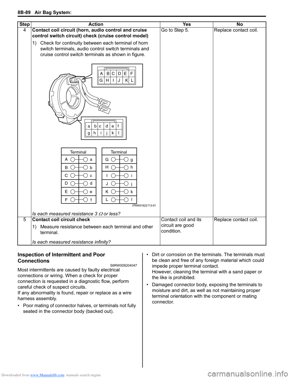
connector. 4Contact coil circuit (horn, audio control and cruise
control switch circuit) check (cruise control model)
1) Check for continuity between each terminal of horn
switch terminals, audio control switch terminals and
cruise control switch terminals as shown in figure.
Is each measured resistance 3
Ω or less?Go to Step 5. Replace contact coil.
5Contact coil circuit check
1) Measure resistance between each terminal and other
terminal.
Is each measured resistance infinity?Contact coil and its
circuit are good
condition.Replace contact coil. Step Action Yes No
ABCDEF
GH I J KL
a bc def
gh i j k l
A
B
C
Da
b
c
d
Terminal
E
Fe
f
I
J
K
Li
j
k
l
Terminal
G
Hg
h
I7RW01822113-01
Page 1162 of 1556
Downloaded from www.Manualslib.com manuals search engine 9-ii Table of Contents
B-9 Keyless Start System Circuit Diagram...... 9A-103
C-1 Combination Meter Circuit Diagram
(Meter) .......................................................... 9A-104
C-2 Combination Meter Circuit Diagram
(Indicator) ...................................................... 9A-105
C-3 Combination Meter Circuit Diagram
(Warning Light) ............................................. 9A-106
D-1 Headlight System Circuit Diagram
(Except Taiwan) ............................................ 9A-108
D-1 Headlight System Circuit Diagram
(Taiwan) ........................................................ 9A-110
D-2 Position, Tail and Licence Plate Light
System Circuit Diagram (Except Taiwan) ..... 9A-111
D-2 Position, Tail and Licence Plate Light
System Circuit Diagram (Taiwan) ................. 9A-112
D-3 Front Fog Light System Circuit Diagram
(Except Taiwan) ............................................ 9A-113
D-3 Front Fog Light System Circuit Diagram
(Taiwan) ........................................................ 9A-114
D-4 Illumination Light System Circuit Diagram
(Except Taiwan) ............................................ 9A-115
D-4 Illumination Light System Circuit Diagram
(Taiwan) ........................................................ 9A-116
D-5 Interior Light System Circuit Diagram
(Except Taiwan) ............................................ 9A-117
D-5 Interior Light System Circuit Diagram
(Taiwan) ........................................................ 9A-118
D-6 Turn Signal and Hazard Warning Light
System Circuit Diagram (Except Taiwan) ..... 9A-119
D-6 Turn Signal and Hazard Warning Light
System Circuit Diagram (Taiwan) ................. 9A-121
D-7 Brake Light System Circuit Diagram ........ 9A-123
D-8 Back-Up Light System Circuit Diagram .... 9A-124
D-9 Headlight Beam Leveling System Circuit
Diagram (Manual Leveling)........................... 9A-125
D-10 Rear Fog Light Circuit Diagram .............. 9A-126
E-1 Heater System Circuit Diagram ................ 9A-127
E-2 Auto A/C System Circuit Diagram ............ 9A-129
F-1 Air-Bag System Circuit Diagram (4ch) ...... 9A-131
F-1 Air-Bag System Circuit Diagram (8ch) ...... 9A-132
F-2 Anti-Lock Brake System Circuit Diagram.. 9A-134
F-4 Power Steering System Circuit Diagram .. 9A-136
G-1 Audio System Circuit Diagram ................. 9A-138
G-2 Multi Information Display / Accessory
Socket System Circuit Diagram .................... 9A-140
G-4 Navigation System Circuit Diagram ......... 9A-141
List of Connector .............................................9A-143
List of Connectors ........................................... 9A-143
C Connector .................................................... 9A-143
E Connector .................................................... 9A-145
G Connector .................................................... 9A-146
J Connector ..................................................... 9A-149
K Connector .................................................... 9A-149
L Connector..................................................... 9A-150
O Connector .................................................... 9A-152
Q Connector (8ch)........................................... 9A-152
R Connector .................................................... 9A-152
S Connector .................................................... 9A-152
Lighting Systems .................................... 9B-1
Precautions ...........................................................9B-1
Precautions for Discharge Headlight Service
(If Equipped)...................................................... 9B-1
Precautions in Diagnosing Troubles
(Headlight Auto Leveling System) ..................... 9B-1
General Description .............................................9B-1
Discharge Headlight Description (If
Equipped) .......................................................... 9B-1
Headlight Auto Leveling System Description
(If Equipped)...................................................... 9B-2
Auto-On Headlight System Description (If
Equipped) .......................................................... 9B-4
Schematic and Routing Diagram ........................9B-5
Headlight Auto Leveling System Wiring
Circuit Diagram ................................................. 9B-5
Component Location ...........................................9B-6
Lighting System Components Location............... 9B-6
Interior Light System Location............................. 9B-7
Diagnostic Information and Procedures ............9B-7
Self-Diagnosis Function for Headlight Auto
Leveling System ................................................ 9B-7
Headlight Leveling Warning Light Check ............ 9B-8
Headlight Symptom Diagnosis (Discharge
Headlight Model) ............................................... 9B-8
Headlight Symptom diagnosis (Other than
Discharge Headlight Model) .............................. 9B-9
Auto-On Headlight System Symptom
Diagnosis (If Equipped) ..................................... 9B-9
DRL System Symptom Diagnosis (If
Equipped) ........................................................ 9B-10
Headlight Auto Leveling System Symptom
Diagnosis (If Equipped) ................................... 9B-10
Headlight Manual Leveling System Symptom
Diagnosis (If Equipped) ................................... 9B-10
Turn Signal and Hazard Warning Light
Symptom Diagnosis ........................................ 9B-11
Clearance, Tail and License Plate Light
Symptom Diagnosis ........................................ 9B-11
Back-Up Light Symptom Diagnosis................... 9B-12
Brake Light Symptom Diagnosis ....................... 9B-12
Front Fog Light Symptom Diagnosis (If
Equipped) ........................................................ 9B-12
Rear Fog Light Symptom Diagnosis (If
Equipped) ........................................................ 9B-12
Illumination Cancel System Symptom
Diagnosis (If Equipped) ................................... 9B-13
Interior Light Symptom Diagnosis ..................... 9B-13
DRL Operation Inspection (If Equipped) ........... 9B-13
Inspection of DRL Controller and Its Circuits
(If Equipped).................................................... 9B-13
Auto-On Headlight Operation Inspection (If
Equipped) ........................................................ 9B-15
Inspection of Auto-On Headlight Controller
and Its Circuit (If Equipped)............................. 9B-15
Inspection of Headlight Leveling Control
Module and Its Circuit (Headlight Auto
Leveling System)............................................. 9B-16
Repair Instructions ............................................9B-18
Headlight Housing Removal and Installation .... 9B-18
Page 1163 of 1556
Downloaded from www.Manualslib.com manuals search engine Table of Contents 9-iii
Headlight Bulb Replacement (Discharge
Headlight Model) ............................................. 9B-19
Ballast Removal and Installation (Discharge
Headlight Model) ............................................. 9B-19
Igniter Removal and Installation (Discharge
Headlight Model) ............................................. 9B-20
Headlight Aiming Adjustment with Screen ........ 9B-20
Headlight Switch (in Lighting Switch)
Removal and Installation................................. 9B-22
Headlight Switch (in Lighting Switch)
Inspection........................................................ 9B-22
Hazard Warning Switch Removal and
Installation ....................................................... 9B-23
Hazard Warning Switch Inspection ................... 9B-23
Brake Light Switch Inspection ........................... 9B-23
Turn Signal Light Switch (in Lighting Switch)
Removal and Installation................................. 9B-24
Turn Signal Light Switch (in Lighting Switch)
Inspection........................................................ 9B-24
Turn Signal and Hazard Warning Relay
Removal and Installation................................. 9B-24
Turn Signal and Hazard Warning Relay
Inspection........................................................ 9B-25
License Light Assembly Removal and
Installation ....................................................... 9B-25
Front Fog Light Assembly Removal and
Installation (If Equipped) ................................. 9B-26
Front Fog Light Switch Inspection (If
Equipped)........................................................ 9B-26
Front Fog Light Aiming Adjustment with
Screen (If Equipped) ....................................... 9B-26
Rear Fog Light Switch Inspection (If
Equipped)........................................................ 9B-27
Headlight Manual Levering Switch Inspection
(If Equipped) ................................................... 9B-28
Headlight Leveling Actuator Inspection (If
Equipped)........................................................ 9B-28
Height Sensor Removal and Installation (If
Equipped)........................................................ 9B-29
Height Sensor and Its Circuit Inspection (If
Equipped)........................................................ 9B-30
Headlight Leveling Control Module Removal
and Installation (If Equipped) .......................... 9B-30
Initialization of Headlight Auto Leveling
System ............................................................ 9B-30
Auto-On Headlight Sensor Inspection (If
Equipped)........................................................ 9B-31
Illumination Cancel Switch Inspection (If
Equipped)........................................................ 9B-32
Tail Light Relay, Headlight Relay, Front Fog
Light Relay Inspection (If Equipped) ............... 9B-32
Specifications..................................................... 9B-33
Tightening Torque Specifications ...................... 9B-33
Instrumentation / Driver Info. / Horn ...... 9C-1
Precautions........................................................... 9C-1
Precautions in Diagnosing Troubles for
Combination Meter............................................ 9C-1
General Description ............................................. 9C-1
CAN Communication System Description........... 9C-1Auto Volume Control System Description (If
Equipped) ..........................................................9C-3
Schematic and Routing Diagram ........................9C-4
Combination Meter Circuit Diagram ....................9C-4
Component Location ...........................................9C-5
Audio System Component Location ....................9C-5
Diagnostic Information and Procedures ............9C-6
Speedometer and VSS Symptom Diagnosis ......9C-6
Tachometer Symptom Diagnosis ........................9C-6
Engine Coolant Temperature (ECT) Meter
Symptom Diagnosis ..........................................9C-6
Fuel Meter Symptom Diagnosis ..........................9C-6
Low Fuel Warning Light Symptom Diagnosis .....9C-7
Oil Pressure Warning Light Symptom
Diagnosis ..........................................................9C-7
Brake and Parking Brake Warning Light
Symptom Diagnosis ..........................................9C-8
Seat Belt Reminder Light Symptom Diagnosis ....9C-8
A/T Shift Position Indicator Symptom
Diagnosis (A/T Model).......................................9C-8
Charge Warning Light Symptom Diagnosis ........9C-9
Main Beam (High Beam) Indicator Symptom
Diagnosis ..........................................................9C-9
Warning Buzzer Circuit Symptom Diagnosis ......9C-9
Cigarette Lighter Symptom Diagnosis (If
Equipped) ........................................................9C-10
Horn Symptom Diagnosis .................................9C-10
Information Display Symptom Diagnosis (If
Equipped) ........................................................9C-10
Clock System Diagnosis (If Equipped) ..............9C-11
Audio System Symptom Diagnosis (If
Equipped) ........................................................9C-12
Remote Audio Control Switch Symptom
Diagnosis (If Equipped) ...................................9C-13
Navigation Symptom Diagnosis (If Equipped)...9C-13
Repair Instructions ............................................9C-14
Ignition Switch Removal and Installation...........9C-14
Ignition Switch Inspection..................................9C-14
Combination Meter Removal and Installation ...9C-14
Fuel Level Sensor Removal and Installation .....9C-15
Fuel Level Sensor Inspection ............................9C-15
Oil Pressure Switch Removal and Installation ..9C-15
Oil Pressure Switch Inspection .........................9C-15
Engine Coolant Temperature (ECT) Sensor
Inspection ........................................................9C-16
Brake Fluid Level Switch Inspection .................9C-16
Parking Brake Switch Inspection.......................9C-16
Door Switch (Front / Rear Door) Inspection ......9C-16
Rear End Door Switch Inspection .....................9C-16
Outside Air Temperature Sensor Removal
and Installation (If Equipped) ..........................9C-17
Outside Air Temperature Sensor Inspection
(If Equipped)....................................................9C-17
Instrument Panel Removal and Installation.......9C-17
Information Display (Clock) Removal and
Installation .......................................................9C-18
Audio Unit Removal and Installation (If
Equipped) ........................................................9C-19
Page 1164 of 1556
Downloaded from www.Manualslib.com manuals search engine 9-iv Table of Contents
Front Speaker Removal and Installation (If
Equipped) ........................................................9C-19
Rear Speaker Removal and Installation (If
Equipped) ........................................................9C-19
GPS Antenna Removal and Installation (If
Equipped) ........................................................9C-20
Horn Removal and Installation ..........................9C-20
Horn Inspection .................................................9C-20
Horn Relay Inspection .......................................9C-20
Antenna Base Removal and Installation ...........9C-21
Remote Audio Control Switch Removal and
Installation (If Equipped) .................................9C-21
Remote Audio Control Switch Inspection (If
Equipped) ........................................................9C-22
Vehicle Speed Signal Inspection (For Audio
Unit) (If Equipped) ...........................................9C-22
Specifications .....................................................9C-22
Tightening Torque Specifications ......................9C-22
Wipers / Washers .................................... 9D-1
Diagnostic Information and Procedures ............ 9D-1
Front Wiper and Washer Symptom Diagnosis ....9D-1
Rear Wiper and Washer Symptom Diagnosis..... 9D-1
Repair Instructions ..............................................9D-2
Wipers and Washers Components .....................9D-2
Washer Tank and Washer Pump Removal
and Installation ..................................................9D-3
Washer Pump Inspection ....................................9D-3
Windshield Wiper Removal and Installation ........9D-3
Windshield Wiper Motor Inspection.....................9D-4
Rear Wiper Removal and Installation.................. 9D-6
Rear Wiper Motor Inspection ..............................9D-7
Windshield Wiper and Washer Switch
Removal and Installation ................................... 9D-8
Windshield Wiper and Washer Switch
Inspection .......................................................... 9D-8
Rear Wiper and Washer Switch Removal and
Installation .......................................................9D-10
Rear Wiper and Washer Switch Inspection.......9D-10
Rear Wiper Relay Removal and Installation .....9D-10
Rear Wiper Relay Inspection ............................9D-10
Specifications .....................................................9D-11
Tightening Torque Specifications ......................9D-11
Glass / Windows / Mirrors .......................9E-1
Precautions........................................................... 9E-1
Precautions for Power Window Service
(Pinching Prevention Function Model) .............. 9E-1
General Description ............................................. 9E-1
Rear End Door Window Defogger System
Description ........................................................ 9E-1
Schematic and Routing Diagram ........................ 9E-2
Power Window Circuit Diagram (Pinching
Prevention Function Model) .............................. 9E-2
Diagnostic Information and Procedures ............ 9E-3
Rear End door Window Defogger Symptom
Diagnosis .......................................................... 9E-3
Power Window Control System Symptom
Diagnosis .......................................................... 9E-3Inspection of Pinching Prevention Function
(Pinching Prevention Function Model) .............. 9E-4
Power Door Mirror Control System Symptom
Diagnosis .......................................................... 9E-4
Door Mirror Heater Symptom Diagnosis (If
Equipped) .......................................................... 9E-5
Repair Instructions .............................................. 9E-5
Windshield Components ..................................... 9E-5
Windshield Removal and Installation .................. 9E-6
Front Pillar Window Components...................... 9E-10
Front Pillar Window Removal and Installation... 9E-10
Rear Quarter Window Components .................. 9E-11
Rear Quarter Window Removal and
Installation ....................................................... 9E-11
Rear End Door Window Components ............... 9E-12
Rear End Door Glass Removal and
Installation ....................................................... 9E-12
Front Door Window Components ...................... 9E-13
Front Door Glass Removal and Installation ...... 9E-14
Front Door Window Regulator Removal and
Installation ....................................................... 9E-15
Front Door Window Regulator Inspection ......... 9E-15
Rear Door Window Components ...................... 9E-16
Rear Door Glass Removal and Installation ....... 9E-16
Rear Door Window Regulator Removal and
Installation ....................................................... 9E-18
Rear Door Window Regulator Inspection .......... 9E-18
Rear End Door Window Defogger Switch
Inspection ........................................................ 9E-18
Rear End Door Window Defogger Relay
Inspection ........................................................ 9E-19
Rear End Door Window Defogger Wire
Inspection ........................................................ 9E-19
Rear End Door Window Defogger Wire
Repair.............................................................. 9E-20
Power Window Main Switch Inspection ............ 9E-20
Power Window Sub Switch Inspection .............. 9E-22
Pulse Sensor and Its Circuit Inspection
(Pinching Prevention Function Model) ............ 9E-23
Power Window Main Switch Initialization
(Pinching Prevention Function Model) ............ 9E-24
Door Mirror Components................................... 9E-24
Door Mirror Removal and Installation................ 9E-25
Power Door Mirror Switch Inspection ................ 9E-25
Power Door Mirror Actuator Inspection ............. 9E-25
Door Mirror Heater Inspection (If Equipped) ..... 9E-26
Door Mirror Heater Switch Inspection (If
Equipped) ........................................................ 9E-26
Special Tools and Equipment ........................... 9E-26
Recommended Service Material ....................... 9E-26
Security and Locks...................................9F-1
General Description ............................................. 9F-1
Key Coding Construction .................................... 9F-1
Rear End Door Opener System Description ....... 9F-1
Component Location ........................................... 9F-2
Power Door Lock and Keyless Entry System
Component Location (If Equipped) ................... 9F-2
Diagnostic Information and Procedures ............ 9F-3
Page 1188 of 1556
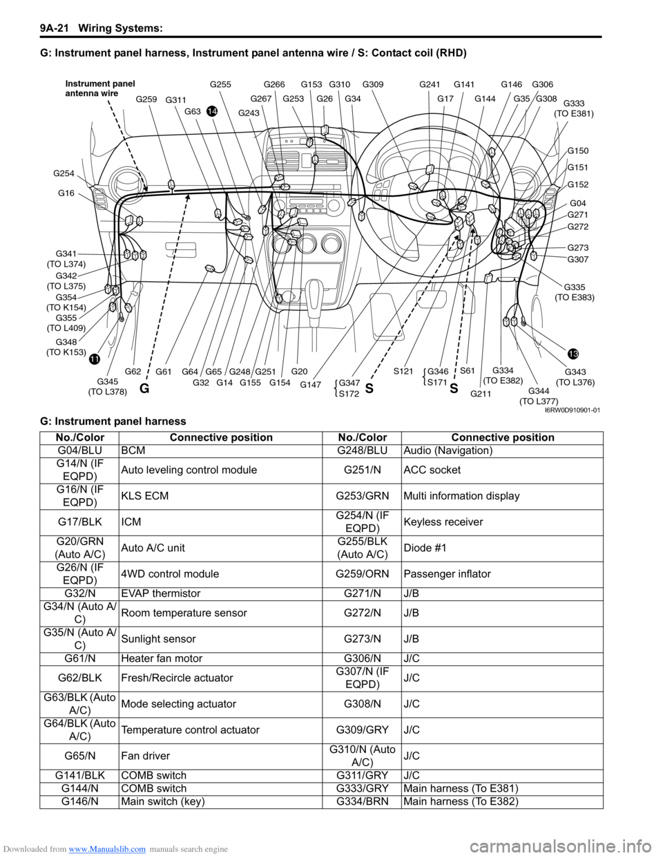
Downloaded from www.Manualslib.com manuals search engine 9A-21 Wiring Systems:
G: Instrument panel harness, Instrument panel antenna wire / S: Contact coil (RHD)
G: Instrument panel harness
G146G141G309
G34G26G253
G266G255
G144
G241
G17
G310G153
G248
G311
G61
G259
1311
14
G16
G341
(TO L374)
G354
(TO K154)
G342
(TO L375)
G348
(TO K153)
G254
G152
G04
G271
G272
G307
G211
G343
(TO L376)
G344
(TO L377) G147G345
(TO L378)
G334
(TO E382)
G333
(TO E381)
G20
S121S61
G32 G155 G154
G63
G62G65G64G273
G151
G150
G308
G306
G35
G251
G347
S172
G346
S171
GSS
Instrument panel
antenna wire
G243
G267
G14
G355
(TO L409)G335
(TO E383)
I6RW0D910901-01
No./Color Connective position No./Color Connective position
G04/BLU BCM G248/BLU Audio (Navigation)
G14/N (IF
EQPD)Auto leveling control module G251/N ACC socket
G16/N (IF
EQPD)KLS ECM G253/GRN Multi information display
G17/BLK ICMG254/N (IF
EQPD)Keyless receiver
G20/GRN
(Auto A/C)Auto A/C unitG255/BLK
(Auto A/C)Diode #1
G26/N (IF
EQPD)4WD control module G259/ORN Passenger inflator
G32/N EVAP thermistor G271/N J/B
G34/N (Auto A/
C)Room temperature sensor G272/N J/B
G35/N (Auto A/
C)Sunlight sensor G273/N J/B
G61/N Heater fan motor G306/N J/C
G62/BLK Fresh/Recircle actuatorG307/N (IF
EQPD)J/C
G63/BLK (Auto
A/C)Mode selecting actuator G308/N J/C
G64/BLK (Auto
A/C)Temperature control actuator G309/GRY J/C
G65/N Fan driverG310/N (Auto
A/C)J/C
G141/BLK COMB switch G311/GRY J/C
G144/N COMB switch G333/GRY Main harness (To E381)
G146/N Main switch (key) G334/BRN Main harness (To E382)
Page 1189 of 1556
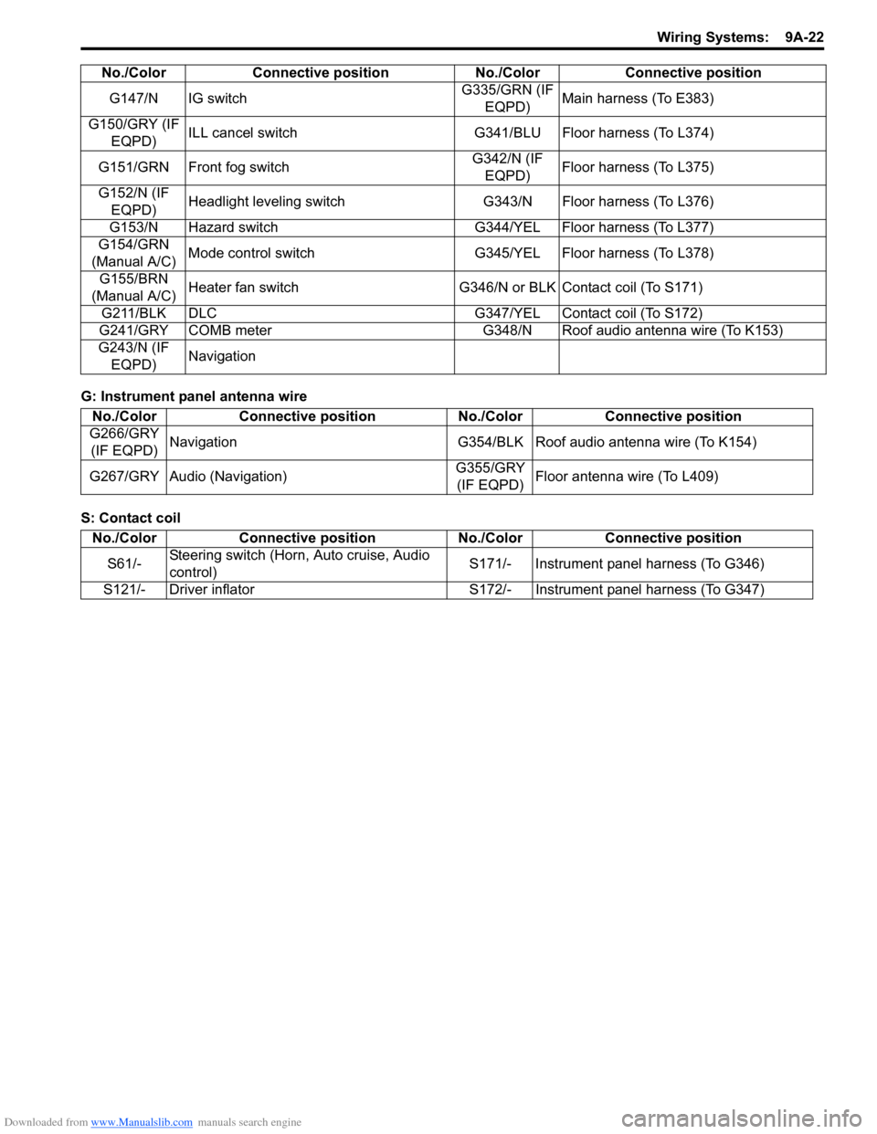
Downloaded from www.Manualslib.com manuals search engine Wiring Systems: 9A-22
G: Instrument panel antenna wire
S: Contact coilG147/N IG switchG335/GRN (IF
EQPD)Main harness (To E383)
G150/GRY (IF
EQPD)ILL cancel switch G341/BLU Floor harness (To L374)
G151/GRN Front fog switchG342/N (IF
EQPD)Floor harness (To L375)
G152/N (IF
EQPD)Headlight leveling switch G343/N Floor harness (To L376)
G153/N Hazard switch G344/YEL Floor harness (To L377)
G154/GRN
(Manual A/C)Mode control switch G345/YEL Floor harness (To L378)
G155/BRN
(Manual A/C)Heater fan switch G346/N or BLK Contact coil (To S171)
G211/BLK DLC G347/YEL Contact coil (To S172)
G241/GRY COMB meter G348/N Roof audio antenna wire (To K153)
G243/N (IF
EQPD)Navigation No./Color Connective position No./Color Connective position
No./Color Connective position No./Color Connective position
G266/GRY
(IF EQPD)Navigation G354/BLK Roof audio antenna wire (To K154)
G267/GRY Audio (Navigation)G355/GRY
(IF EQPD)Floor antenna wire (To L409)
No./Color Connective position No./Color Connective position
S61/-Steering switch (Horn, Auto cruise, Audio
control)S171/- Instrument panel harness (To G346)
S121/- Driver inflator S172/- Instrument panel harness (To G347)
Page 1190 of 1556
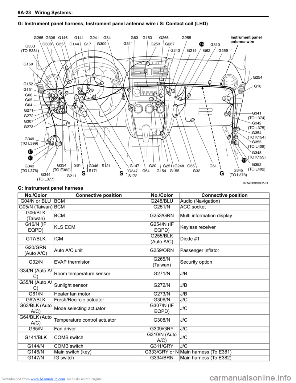
Downloaded from www.Manualslib.com manuals search engine 9A-23 Wiring Systems:
G: Instrument panel harness, Instrument panel antenna wire / S: Contact coil (LHD)
G: Instrument panel harness
G146G141
G309
G34
G253
G266G255
G144
G241
G17G311
G153 G63
G248
G310
G61
G259G243
G267
G355
(TO L409)
1311
14
G16
G341
(TO L374)
G354
(TO K154)
G342
(TO L375)
G348
(TO K153)
G352
(TO L402)
G254
G04
G271
G272
G307
12
G211
G343
(TO L376)G349
(TO L399)
G344
(TO L377)G147G345
(TO L378)
G334
(TO E382)
G333
(TO E381)
G20
S121S61
G32 G155 G154 G64
G62G214
G65 G273
G151
G152 G150
G05 G06
G308
G306 G265
G35
G251
G347
S172
G346
S171
G S S
Instrument panel
antenna wire
I6RW0D910902-01
No./Color Connective position No./Color Connective position
G04/N or BLU BCM G248/BLU Audio (Navigation)
G05/N (Taiwan) BCM G251/N ACC socket
G06/BLK
(Taiwan)BCM G253/GRN Multi information display
G16/N (IF
EQPD)KLS ECMG254/N (IF
EQPD)Keyless receiver
G17/BLK ICMG255/BLK
(Auto A/C)Diode #1
G20/GRN
(Auto A/C)Auto A/C unit G259/ORN Passenger inflator
G32/N EVAP thermistorG265/N
(Taiwan)Security option
G34/N (Auto A/
C)Room temperature sensor G271/N J/B
G35/N (Auto A/
C)Sunlight sensor G272/N J/B
G61/N Heater fan motor G273/N J/B
G62/BLK Fresh/Recircle actuator G306/N J/C
G63/BLK (Auto
A/C)Mode selecting actuatorG307/N (IF
EQPD)J/C
G64/BLK (Auto
A/C)Temperature control actuator G308/N J/C
G65/N Fan driver G309/GRY J/C
G141/BLK COMB switchG310/N (Auto
A/C)J/C
G144/N COMB switch G311/GRY J/C
G146/N Main switch (key) G333/GRY or N Main harness (To E381)
G147/N IG switch G334/BRN Main harness (To E382)
Page 1191 of 1556
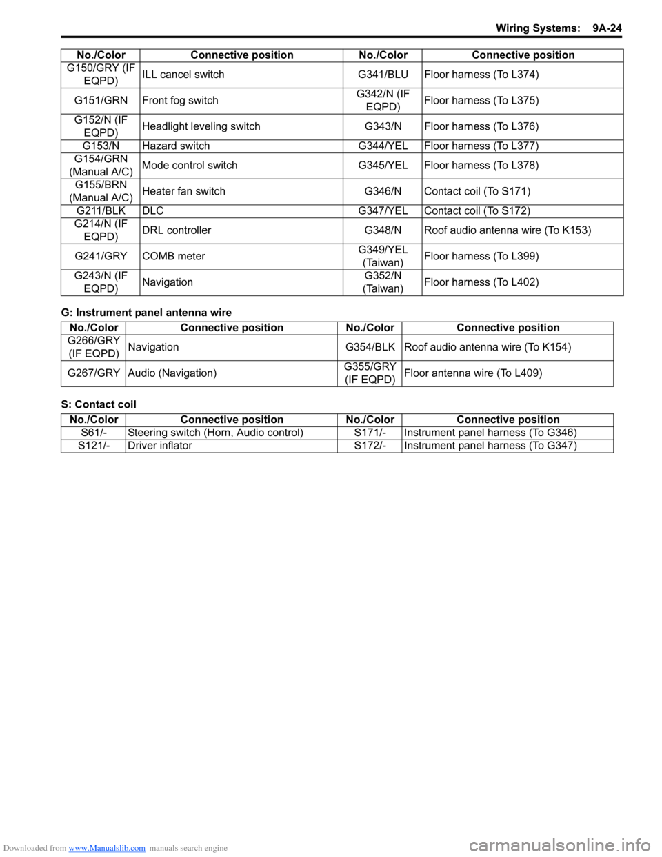
Downloaded from www.Manualslib.com manuals search engine Wiring Systems: 9A-24
G: Instrument panel antenna wire
S: Contact coilG150/GRY (IF
EQPD)ILL cancel switch G341/BLU Floor harness (To L374)
G151/GRN Front fog switchG342/N (IF
EQPD)Floor harness (To L375)
G152/N (IF
EQPD)Headlight leveling switch G343/N Floor harness (To L376)
G153/N Hazard switch G344/YEL Floor harness (To L377)
G154/GRN
(Manual A/C)Mode control switch G345/YEL Floor harness (To L378)
G155/BRN
(Manual A/C)Heater fan switch G346/N Contact coil (To S171)
G211/BLK DLC G347/YEL Contact coil (To S172)
G214/N (IF
EQPD)DRL controller G348/N Roof audio antenna wire (To K153)
G241/GRY COMB meterG349/YEL
(Taiwan)Floor harness (To L399)
G243/N (IF
EQPD)NavigationG352/N
(Taiwan)Floor harness (To L402) No./Color Connective position No./Color Connective position
No./Color Connective position No./Color Connective position
G266/GRY
(IF EQPD)Navigation G354/BLK Roof audio antenna wire (To K154)
G267/GRY Audio (Navigation)G355/GRY
(IF EQPD)Floor antenna wire (To L409)
No./Color Connective position No./Color Connective position
S61/- Steering switch (Horn, Audio control)S171/- Instrument panel harness (To G346)
S121/- Driver inflator S172/- Instrument panel harness (To G347)