2006 SUZUKI SX4 ad blue
[x] Cancel search: ad bluePage 804 of 1556

Downloaded from www.Manualslib.com manuals search engine 5A-156 Automatic Transmission/Transaxle:
68) Install new O-rings to each accumulator piston and
apply A/T fluid to them.
Accumulator O-ring dimension
NOTE
Make sure that O-rings are not twisted or
caught when installing.
69) Install B1, C1, C2 accumulator pistons and springs.
Accumulator piston identification
Accumulator spring identification
70) After applying A/T fluid to cooler check valve (1) and
spring (2), install them to transaxle case (3).
71) After applying A/T fluid to new governor apply No.1
gasket (1), install it to transaxle case. O-ring nameInside
diameterSection
diameter
Large B1 accumulator O-ring (2)
Large C1 accumulator O-ring (2)
Large C2 accumulator O-ring (2)
– Above three O-rings are same.29.4 mm
(1.16 in.)2.6 mm
(0.10 in.)
Small B1 accumulator O-ring (4)19.7 mm
(0.78 in.)2.6 mm
(0.10 in.)
Small C1 accumulator O-ring (6)
Small C2 accumulator O-ring (6)
– Above two O-rings are same.21.8 mm
(0.86 in.)2.6 mm
(0.10 in.)
Piston nameIdentification as
embossed letters on
piston
B1 accumulator piston (3) SB-1
C1 accumulator piston (5) SC-1
C2 accumulator piston (8) SC-2
Spring nameColor of identification
paint
B1 accumulator No.2
spring (1)Pink
C1 accumulator No.2
spring (7)Blue
C2 accumulator No.2
spring (9)Light green
I2RH0B510318-01
I2RH0B510319-01
I2RH0B510320-01
Page 827 of 1556

Downloaded from www.Manualslib.com manuals search engine Manual Transmission/Transaxle: 5B-15
Gear Shift and Select Shaft Assembly
Disassembly and Reassembly
S6RW0D5206013
1) Push spring pins out using 2.8 – 3.0 mm (0.11 – 0.12
in.) commercially available spring pin remover and
specified spring pin removers as shown bellow.
Special tool
(A): 09922–85811 4.5 mm
(B): 09925–78210 6.0 mm
2) Inspect component parts for wear, distortion or
damage. If any detect is found, replace detective
part with new one.
NOTE
• When driving in spring pins, prevent shaft
from being bent by supporting it with wood
block.
• Assemble 5th & reverse gear shift cam
with its pit and spring pin aligned.
• Make sure to select an appropriate spring
by identifying the painted colors to keep
gear shifting performance as designed.
– Low speed select spring - Light blue
– Reverse select spring - Pink
1. E-ring 8. Spring pin
2. Washer 9. Gear shift & select shaft
3. Reverse select spring 10. 5th & reverse gear shift cam
4. Gear shift interlock plate 11. Cam guide return spring
5. Ball 12. 5th & reverse gear shift cam guide
6. Gear shift interlock spring 13. Low speed select spring
7. Gear shift & select lever 14. Spring pin remover
I6RW0C520002-01
Page 970 of 1556

Downloaded from www.Manualslib.com manuals search engine 7B-30 Air Conditioning System: Manual Type
A/C System Relay InspectionS6RW0D7216017
NOTE
Do not use blue relay for the substitute of
white relay because internal durability of a
blue relay is different from the durability of a
white relay.
1) Disconnect negative (–) cable from battery.
2) Remove compressor relay (1) or condenser cooling
fan relay (2) from main fuse box (3).
3) Check that there is no continuity between terminal
“c” and “d”. If there is continuity, replace relay.
4) Connect battery positive (+) terminal to terminal “b”
of relay and battery negative (–) terminal to terminal
“a” of relay, and then check continuity between
terminal “c” and “d”. If there is no continuity, replace
relay.
Compressor Drive Belt Inspection and
Adjustment
S6RW0D7216018
Inspection
• Check compressor drive belt (1) for wear, crack,
deformation and cleanliness. If any defect is found,
replace the belt with new one referring to
“Compressor Drive Belt Removal and Installation”.
• Check compressor drive belt tension by measuring
how much it deflects when pushed intermediate point
between magnet clutch pulley (6) and crankshaft
pulley (3) with about 100 N (10 kg) force after rotating
crankshaft pulley 360°. If belt tension is out of
specification, adjust belt tension referring to
“Adjustment”.
Compressor drive belt tension
“a”
: 7 – 8 mm (0.28 – 0.31 in.)
NOTE
When replacing drive belt, adjust drive belt
tension to the following specifications.
New compressor drive belt tension “a”
: 6 – 7 mm (0.24 – 0.28 in.)
Adjustment
1) Loosen tension pulley nut (4).
2) Adjust belt tension by tighten or loosen tension
pulley adjusting bolt (5).
3) Tighten tension pulley nut.
4) Rotate the crankshaft pulley 360°, and then recheck
belt tension.
3
1
2
“a”
“b”“c”
“d”
I5RW0B721023-01
2. Tension pulley
I5RW0A721033-01
Page 1525 of 1556

Downloaded from www.Manualslib.com manuals search engine Keyless Start System: 10E-3
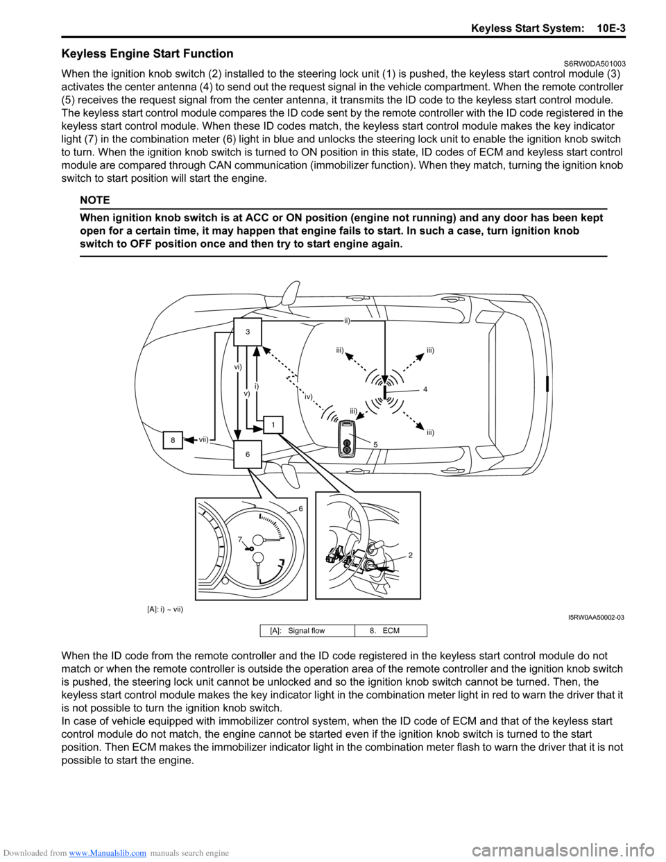
Keyless Engine Start FunctionS6RW0DA501003
When the ignition knob switch (2) installed to the steering lock unit (1) is pushed, the keyless start control module (3)
activates the center antenna (4) to send out the request signal in the vehicle compartment. When the remote controller
(5) receives the request signal from the center antenna, it transmits the ID code to the keyless start control module.
The keyless start control module compares the ID code sent by the remote controller with the ID code registered in the
keyless start control module. When these ID codes match, the keyless start control module makes the key indicator
light (7) in the combination meter (6) light in blue and unlocks the steering lock unit to enable the ignition knob switch
to turn. When the ignition knob switch is turned to ON position in this state, ID codes of ECM and keyless start control
module are compared through CAN communication (immobilizer function). When they match, turning the ignition knob
switch to start position will start the engine.
NOTE
When ignition knob switch is at ACC or ON position (engine not running) and any door has been kept
open for a certain time, it may happen that engine fails to start. In such a case, turn ignition knob
switch to OFF position once and then try to start engine again.
When the ID code from the remote controller and the ID code registered in the keyless start control module do not
match or when the remote controller is outside the operation area of the remote controller and the ignition knob switch
is pushed, the steering lock unit cannot be unlocked and so the ignition knob switch cannot be turned. Then, the
keyless start control module makes the key indicator light in the combination meter light in red to warn the driver that it
is not possible to turn the ignition knob switch.
In case of vehicle equipped with immobilizer control system, when the ID code of ECM and that of the keyless start
control module do not match, the engine cannot be started even if the ignition knob switch is turned to the start
position. Then ECM makes the immobilizer indicator light in the combination meter flash to warn the driver that it is not
possible to start the engine.
[A]: i) ~ vii)
83
1
6ii)
iii) iii)
iii) iii) iv) i)
v) vi)
vii)
76
2
4
5
I5RW0AA50002-03
[A]: Signal flow 8. ECM
Page 1532 of 1556

Downloaded from www.Manualslib.com manuals search engine 10E-10 Keyless Start System:
Customer Questionnaire (Example)S6RW0DA504005
Key Indicator Light CheckS6RW0DA504006
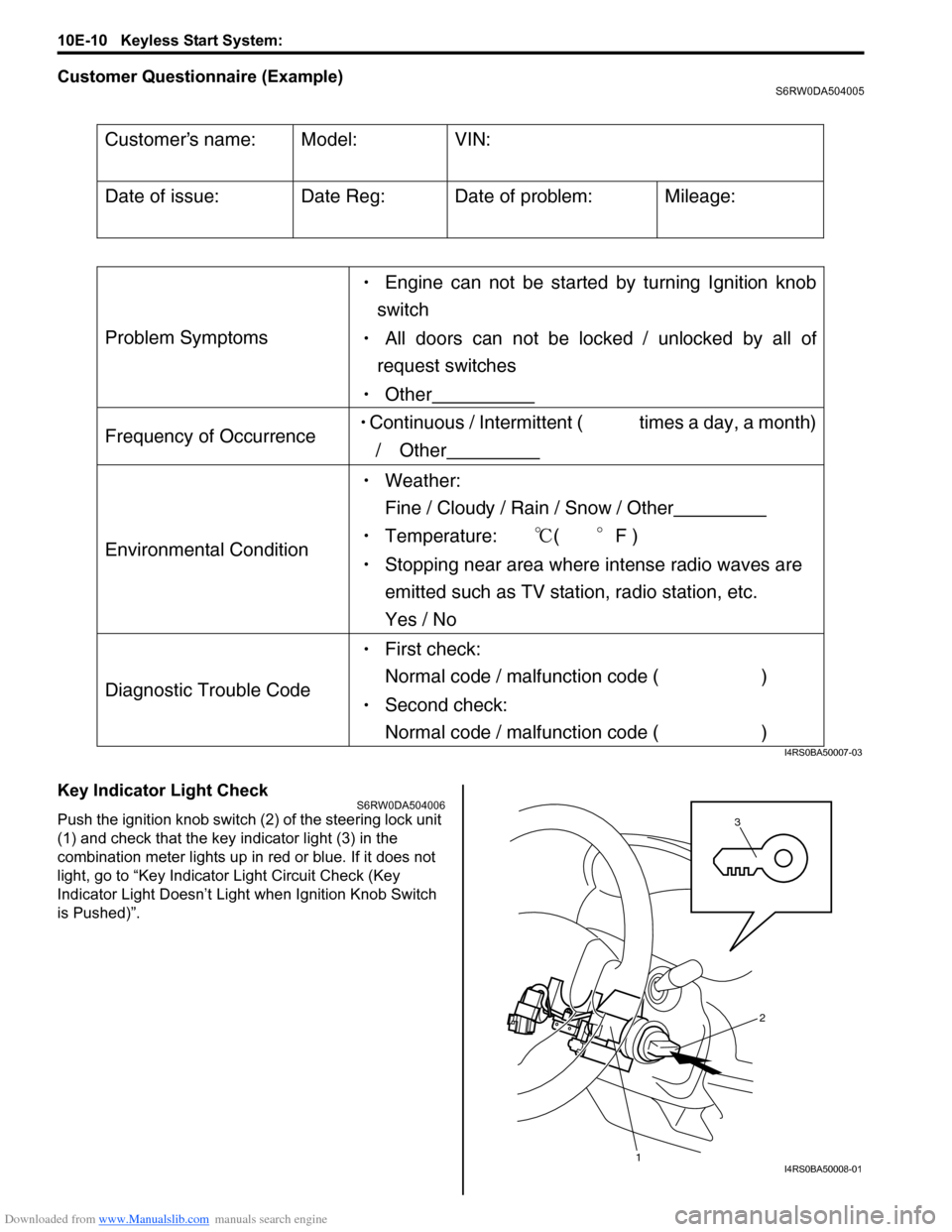
Push the ignition knob switch (2) of the steering lock unit
(1) and check that the key indicator light (3) in the
combination meter lights up in red or blue. If it does not
light, go to “Key Indicator Light Circuit Check (Key
Indicator Light Doesn’t Light when Ignition Knob Switch
is Pushed)”.
Customers name:
Model:
VIN:
Date of issue:
Date Reg:
Date of problem:
Mileage:
Problem Symptoms
Engine can not be started by turning Ignition knob
switch
All doors can not be locked / unlocked by all of
request switches
Other
Frequency of Occurrence Continuous / Intermittent ( times a day, a month)
/ Other
Environmental Condition
Weather:
Fine / Cloudy / Rain / Snow / Other
Temperature: (F )
Stopping near area where intense radio waves are
emitted such as TV station, radio station, etc.
Yes / No
Diagnostic Trouble Code
First check:
Normal code / malfunction code ( )
Second check:
Normal code / malfunction code ( )
I4RS0BA50007-03
3
1
2
I4RS0BA50008-01
Page 1536 of 1556

Downloaded from www.Manualslib.com manuals search engine 10E-14 Keyless Start System:
Keyless Start System Operation InspectionS6RW0DA504011
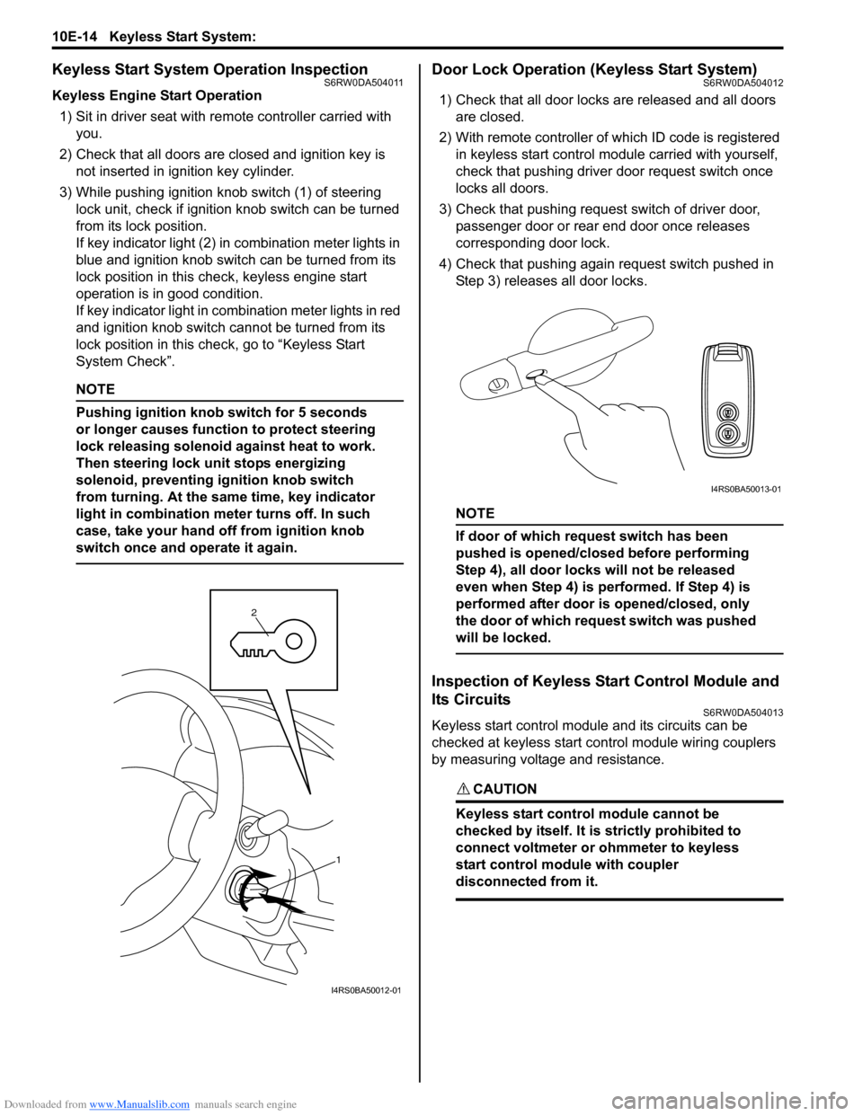
Keyless Engine Start Operation
1) Sit in driver seat with remote controller carried with
you.
2) Check that all doors are closed and ignition key is
not inserted in ignition key cylinder.
3) While pushing ignition knob switch (1) of steering
lock unit, check if ignition knob switch can be turned
from its lock position.
If key indicator light (2) in combination meter lights in
blue and ignition knob switch can be turned from its
lock position in this check, keyless engine start
operation is in good condition.
If key indicator light in combination meter lights in red
and ignition knob switch cannot be turned from its
lock position in this check, go to “Keyless Start
System Check”.
NOTE
Pushing ignition knob switch for 5 seconds
or longer causes function to protect steering
lock releasing solenoid against heat to work.
Then steering lock unit stops energizing
solenoid, preventing ignition knob switch
from turning. At the same time, key indicator
light in combination meter turns off. In such
case, take your hand off from ignition knob
switch once and operate it again.
Door Lock Operation (Keyless Start System)S6RW0DA504012
1) Check that all door locks are released and all doors
are closed.
2) With remote controller of which ID code is registered
in keyless start control module carried with yourself,
check that pushing driver door request switch once
locks all doors.
3) Check that pushing request switch of driver door,
passenger door or rear end door once releases
corresponding door lock.
4) Check that pushing again request switch pushed in
Step 3) releases all door locks.
NOTE
If door of which request switch has been
pushed is opened/closed before performing
Step 4), all door locks will not be released
even when Step 4) is performed. If Step 4) is
performed after door is opened/closed, only
the door of which request switch was pushed
will be locked.
Inspection of Keyless Start Control Module and
Its Circuits
S6RW0DA504013
Keyless start control module and its circuits can be
checked at keyless start control module wiring couplers
by measuring voltage and resistance.
CAUTION!
Keyless start control module cannot be
checked by itself. It is strictly prohibited to
connect voltmeter or ohmmeter to keyless
start control module with coupler
disconnected from it.
1 2
I4RS0BA50012-01
I4RS0BA50013-01
Page 1544 of 1556

Downloaded from www.Manualslib.com manuals search engine 10E-22 Keyless Start System:
Description
When the ignition knob switch is pushed, the key indicator light lights up in blue if you carry the remote controller
registered in the keyless start control module and it lights in red if you carry the remote controller which has not been
registered in the keyless start control module or if you carry no remote controller.
Troubleshooting
Step Action Yes No
1Combination meter power and ground circuit check
1) Turn ignition switch to ON position.
Do warning lights in combination meter other than key
indicator light light up?Go to Step 2. Check main fuse, circuit
fuse, combination meter
power and ground
circuit.
2Keyless start control module power and ground circuit
check
1) Check keyless start control module power and ground
circuit for condition referring to “Keyless Start Control
Module Power and Ground Circuit Check”.
Is it in good condition?Go to Step 3. Repair circuit.
3Steering lock unit ignition knob switch check
1) Check ignition knob switch of steering lock unit for
operation referring to “Steering Lock Unit Inspection”.
Is it in good condition?Go to Step 4. Replace steering lock
unit.
4Wire harness check
1) Turn ignition switch to OFF position.
2) Disconnect connectors from keyless start control
module, steering lock unit and combination meter.
3) Check for open, short and high resistance in following
circuits.
• Ignition knob switch signal circuit
• Keyless start control module and combination meter
CAN communication circuit
Is each circuit in good condition?Go to Step 5. Repair circuit.
5Keyless start system operation check
1) With remote controller of which ID code is registered in
keyless start control module carried with you, try to turn
ignition knob switch.
Can it be turned to any position other than “LOCK” position?Replace combination
meter.Substitute a known-
good keyless start
control module and
recheck.