2006 SUZUKI SX4 Ecm diagram
[x] Cancel search: Ecm diagramPage 1250 of 1556
Downloaded from www.Manualslib.com manuals search engine 9A-83 Wiring Systems:
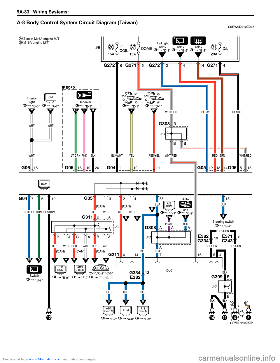
A-8 Body Control System Circuit Diagram (Taiwan)S6RW0D910E043
1G053
WHTRED
2
G211
4
6
14
WHTRED
PNKLT GRN
G05
DLC
4
111412
BLK
BLKBLK
B
B
J/C
G309
18
BLK/WHT
G041
WHT/RED
13
1920
Receiver
35
BLU
15
BLU
BLUBLU
BLUBLU
BLU
WHTWHT
"F-2""F-3"
P/S
Cont.MABS
Cont.M
"B-9"
KLS
ECM
"A-7"
ICM
RW
B
BB
E382
G334E371
C34319
G334
E38212
8
BLK/ORN
5
4
J/B
15ADOME
37
20AD/L
31
15AIG
COIL
20
G271 G2715G27212
BLK/RED
5 4
G2726
WHT/RED
WHT/RED
BLK/ORN
716
B
B
B
J/C
G308
BLK/ORN
A
AA
J/C
G308
B
BA
A
WHTREDWHTRED
RW
BA
J/C
G311
"F-2,"B-9" "C-1","C-2","C-3""B-2" Switch
7G04612
GRNBLU/BLKBLK/ORN
BB
"B-7" Steering switch unit Auto
"E-2""F-1"BB
PPL/WHTA
PW
G
BPLg
WHT
G06G06
BLU/WHT
12 4
RED
13 14
BRN
14G0515
WW"B-5"
Interior
light
"D-5"
Tail light
relay
"D-1"
RW
BCM
BLK
BLU
"A-6"
TCM
B
(CAN)
(CAN) (CAN)
"F-2"
ABS
Cont.M
A/B
SDM
WHTRED
RW
BA
(CAN)(CAN) IF EQPD
"D-1"
YEL
1011
relay
"B-2"
RYY
RED/YEL
"D-1"
relay
"B-3"
Except M16A engine M/T
M16A engine M/T A
A
5
B
B
I6RW0C910955-01
Page 1270 of 1556

Downloaded from www.Manualslib.com manuals search engine 9A-103 Wiring Systems:
B-9 Keyless Start System Circuit DiagramS6RW0D910E018
G271
KLS
ECM
BCM
WHT/RED
WHT/REDWHT/REDWHT/RED
BLU/YEL
WHTRED
WHTRED
ORN
BLU/YEL
"A-8"
W
WR
R
G1614 3420
1819
BLK/ORN
BLK/ORN
9
5
J/B
15ADOME
37
G2728 10ABACK
21
11 15AACC2
24
B
B
BB
J/C J/C
G308BG307
B
A
A
J/C
BLU/WHT
BLU/WHT
C
C
J/C
G307
Main switch
(Key switch)
STEARING
LOCK PUSH
SWITCH
G146456
1
O1223
4
2
BRN29
BRN/YEL
301011
RED/BLK
RED/BLK
B
B
J/C
Rear end
door
request
switch
G306
15ORN
ORN
ORN
1BLK/YEL
WHT/RED
378
STEARING
LOCK UNIT
Door antenna
L375
G34219
J215
L379J15317
2
L391
O2321 12
BLU
BLU
BLU
2
9
18
WHT/BLK
WHT/BLK6
Inside
antenna
6
12
GRN
GRN
5
16
LT GRN
LT GRN8
Luggage
antenna
5
12
GRN/WHT
GRN/WHT
7
15
BLK/YEL
BLK/YEL
BLK/YEL
23
Door antenna
18
J216
L380J154 L294 L293
WHT/GRN
WHT/GRN4
Rear end
antenna
7
12
RED/BLU
RED/BLU
3
17
L292
1712
WHT/BLU
WHT/BLU
WHT/BLU
24
8
18
G307
A
A
J/C
B
BG311
A
A
J/C
G309
13
YEL
YEL
YEL
BLK
BLKBLK
32
J862
1
Request
switch
13
15
BLU/RED
BLU/RED
BLU/RED
36
2321
J32
Actuator
state
switch
14
L380
J21616
7
PNK/BLK
PNK/BLK
PNK/BLK
BLK/ORNBLK/ORN
BLK/ORN
BLK/ORN
37
16
J216
L380
J852
1
Request
switch
3
15
PPL
PPL
PPL
16
J31
Actuator
state
switch
4
L379
J215 G342
L37516
O231
L390213
GRY/BLU
GRY/BLU
GRY/BLU
BLKBLK
BLK
A
A
J/C
L348
33
17
BLK
20
J215
L379
(CAN)
(CAN)
RHD
LHD AB
10
5AB
8
7AB
5
10AB
7
8AB
I6RW0C910972-01
Page 1290 of 1556
Downloaded from www.Manualslib.com manuals search engine 9A-123 Wiring Systems:
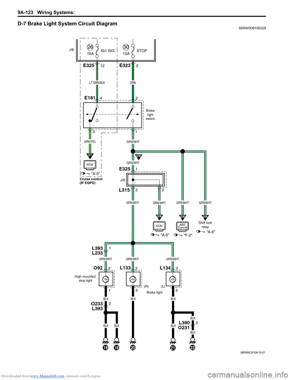
D-7 Brake Light System Circuit DiagramS6RW0D910E028
Brake
light
switch
Shift lock
relay
(R)
Brake light
GRNLT GRN/BLK
BLK
(L)
E181
L134
GRN/WHT
GRN/WHT
GRN/WHTGRN/WHT
5
L315
E325
J/B
"F-2"
ABS
Cont.M
GRN/WHT
2 2 1
"A-5"
ECM
21
GW
GW
GRN/YEL
"A-5"
ECM
GY
GW
42
31
J/B
L1332
52
1
GRN/WHT
"A-6"
GW
O92
High mounted
stop light
201918
BLKBLK
BLKBLKBLK
23
BLK
BLK
2
GRN/WHTGRN/WHTGRN/WHT
E3232
L393
L2331
O233
L3932
L390
O2312 15A
30STOP
E32512 10A
26IG1 SIG
Cruise control
(IF EQPD)
I6RW0C910A15-01
Page 1296 of 1556
Downloaded from www.Manualslib.com manuals search engine 9A-129 Wiring Systems:
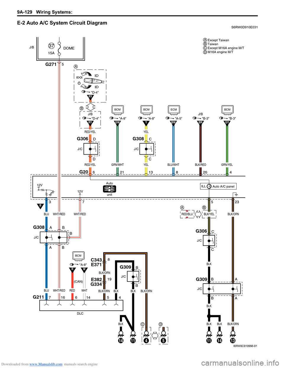
E-2 Auto A/C System Circuit DiagramS6RW0D910E031
Except Taiwan
Taiwan
Except M16A engine M/T
M16A engine M/T ABCD
G20
523 6
12V
BLK
BLK
BLK
BLKBLK/ORN
RED/YEL
26
BLK/RED
RED/YEL
G271
ILL
Auto A/C panel Auto
unit
13
YEL
"A-8"Y"B-3"BR
37
BLUWHT/REDWHT/RED
BLUWHT/RED
BLK/ORNBLK/YEL
12V
REDWHT
8
BLU/WHT
"A-5"BW
4
GRN/YEL
"B-3"GY
J/C
AG308
A
B
B
B
J/CJ/B
21
GRN/WHT
"A-8"GW"D-4"RY
J/B
DG306
D
5
DOME
15A37J/B
J/C
G309AB
B
A
E382
G33419
C343
E3718
BLK/ORN
BLK/ORN
BLK/ORN
716614 54
DLC
RW
B
"A-8"
BCM
BCMBCMECMBCM
(CAN)
G211
J/C
G309
BLKBLK
B
B
J/C
G306C
C
YEL
J/C
CG308
C
111411
BLK
14134
B
RY"D-4"
A
C
5
D
B
RED/BLU
A
I6RW0C910998-01
Page 1301 of 1556

Downloaded from www.Manualslib.com manuals search engine Wiring Systems: 9A-134
F-2 Anti-Lock Brake System Circuit DiagramS6RW0D910E034
2326
24
25
72
13E08
BLK
30A
ABS
SOL
40A
ABS
MOT11
WHT/REDWHT/BLU
GRN/WHT
8
BLK
R
RED
W
WHT
REDWHT
REDWHT
"A-8"
"A-5"
J/B10AABS
28
E3259
GRN/ORN
9
L315
L338
3
2
GRN/YEL
GRN/ORN
6
GW"D-7"
Brake light
switch
Individual circuit
fuse box (No.1)
1
GRN/BLK
GRN/YEL
3
G sensor
L371
E38715
G333
E38112
14
RED
R
112
WHT
W
B
BG311
A
A
RW
J/C
(CAN)(CAN)
Taiwan
(CAN)
9
IF EQPD
GRN/BLK
ABS
Cont.M
BCM
ECM
I6RW0C910A03-01
Page 1471 of 1556
Downloaded from www.Manualslib.com manuals search engine Table of Contents 10- i
10
Section 10
CONTENTS
Control Systems
Precautions ............................................... 10-1
Precautions........................................................... 10-1
Precautions for Control Systems......................... 10-1
Body Electrical Control System ........... 10B-1
Precautions......................................................... 10B-1
Precautions in Diagnosing Trouble ................... 10B-1
General Description ........................................... 10B-1
BCM General Description ................................. 10B-1
CAN Communication System Description......... 10B-1
Theft Deterrent Light ......................................... 10B-2
Security Alarm Description (If Equipped) .......... 10B-2
Schematic and Routing Diagram ...................... 10B-3
Body Electrical Control System Wiring Circuit
Diagram .......................................................... 10B-3
Connector Layout Diagram of BCM and
Junction Block ................................................. 10B-6
Component Location ......................................... 10B-7
BCM and Related System Component
Location .......................................................... 10B-7
Diagnostic Information and Procedures .......... 10B-8
BCM Self-Diagnosis Function ........................... 10B-8
Body Electrical Control System Check.............. 10B-9
Scan Tool Data ............................................... 10B-11
DTC Table ....................................................... 10B-13
DTC Check ..................................................... 10B-14
DTC Clearance ............................................... 10B-15
BCM Power Circuit and Ground Circuit Check 10B-16
DTC B1133 (DTC No. 1133): Battery Voltage
Too High ....................................................... 10B-17
DTC B1141 / DTC B1142 (No. 1141 / No.
1142) Outside Air Temperature (Ambient
Temp.) Sensor Circuit Malfunction ................ 10B-18
DTC B1150 (No. 1150): Air Bag
Communication Circuit Malfunction .............. 10B-19
DTC B1157 (No. 1157) Air Bag Deployment
Signal Input ................................................... 10B-20
DTC B1170 (No. 1170): EEPROM Access
Error .............................................................. 10B-20
DTC U0073 (No. 0073): Control Module
Communication Bus Off ................................ 10B-20
DTC U0100 (No. 0100): Lost Communication
with ECM....................................................... 10B-20DTC U0101 (No. 0101): Lost Communication
with TCM ....................................................... 10B-20
DTC U0155 (No. 0155): Lost Communication
with Instrument Panel Cluster (IPC) Control
Module .......................................................... 10B-20
DTC U1144 (No. 1144): Lost Communication
with Keyless Start Control Module ................ 10B-20
Inspection of BCM and Its Circuits .................. 10B-21
Repair Instructions ..........................................10B-28
BCM (Included in Junction Block) Removal
and Installation .............................................. 10B-28
Security Alarm Mode Selection Procedure (If
Equipped) ...................................................... 10B-29
Outside Air Temperature Sensor Removal
and Installation .............................................. 10B-29
Outside Air Temperature Sensor Inspection ... 10B-29
Special Tools and Equipment .........................10B-29
Special Tool .................................................... 10B-29
Immobilizer Control System ................. 10C-1
Precautions.........................................................10C-1
Precautions in Diagnosing Troubles .................10C-1
Precaution in Replacing ECM ...........................10C-1
Precaution in Replacing Ignition Key ................10C-1
Precautions in Handling Immobilizer Control
System ............................................................10C-1
General Description ...........................................10C-2
Immobilizer Control System Introduction ..........10C-2
On-Board Diagnostic System Description
(Self-diagnosis Function)................................10C-2
Schematic and Routing Diagram ......................10C-3
Immobilizer Control System Wiring Circuit
Diagram...........................................................10C-3
Component Location .........................................10C-5
Immobilizer Control System Components
Location...........................................................10C-5
Diagnostic Information and Procedures ..........10C-5
Immobilizer Control System Check ...................10C-5
DTC Check........................................................10C-6
DTC Clearance .................................................10C-6
DTC Table .........................................................10C-7
Scan Tool Data .................................................10C-8
Immobilizer Indicator Light Does Not Come
ON with Ignition Switch ON and Engine Stop ..10C-9
Page 1472 of 1556
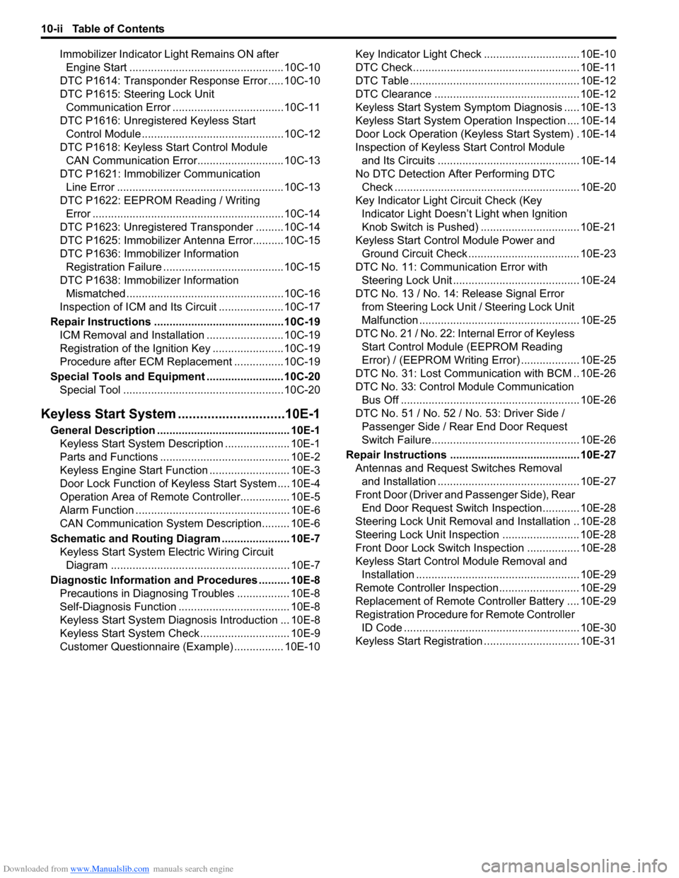
Downloaded from www.Manualslib.com manuals search engine 10-ii Table of Contents
Immobilizer Indicator Light Remains ON after
Engine Start ..................................................10C-10
DTC P1614: Transponder Response Error .....10C-10
DTC P1615: Steering Lock Unit
Communication Error ....................................10C-11
DTC P1616: Unregistered Keyless Start
Control Module ..............................................10C-12
DTC P1618: Keyless Start Control Module
CAN Communication Error............................10C-13
DTC P1621: Immobilizer Communication
Line Error ......................................................10C-13
DTC P1622: EEPROM Reading / Writing
Error ..............................................................10C-14
DTC P1623: Unregistered Transponder .........10C-14
DTC P1625: Immobilizer Antenna Error..........10C-15
DTC P1636: Immobilizer Information
Registration Failure .......................................10C-15
DTC P1638: Immobilizer Information
Mismatched ...................................................10C-16
Inspection of ICM and Its Circuit .....................10C-17
Repair Instructions ..........................................10C-19
ICM Removal and Installation .........................10C-19
Registration of the Ignition Key .......................10C-19
Procedure after ECM Replacement ................10C-19
Special Tools and Equipment .........................10C-20
Special Tool ....................................................10C-20
Keyless Start System .............................10E-1
General Description ........................................... 10E-1
Keyless Start System Description ..................... 10E-1
Parts and Functions .......................................... 10E-2
Keyless Engine Start Function .......................... 10E-3
Door Lock Function of Keyless Start System .... 10E-4
Operation Area of Remote Controller................ 10E-5
Alarm Function .................................................. 10E-6
CAN Communication System Description......... 10E-6
Schematic and Routing Diagram ...................... 10E-7
Keyless Start System Electric Wiring Circuit
Diagram .......................................................... 10E-7
Diagnostic Information and Procedures .......... 10E-8
Precautions in Diagnosing Troubles ................. 10E-8
Self-Diagnosis Function .................................... 10E-8
Keyless Start System Diagnosis Introduction ... 10E-8
Keyless Start System Check ............................. 10E-9
Customer Questionnaire (Example) ................ 10E-10Key Indicator Light Check ............................... 10E-10
DTC Check...................................................... 10E-11
DTC Table ....................................................... 10E-12
DTC Clearance ............................................... 10E-12
Keyless Start System Symptom Diagnosis ..... 10E-13
Keyless Start System Operation Inspection .... 10E-14
Door Lock Operation (Keyless Start System) . 10E-14
Inspection of Keyless Start Control Module
and Its Circuits .............................................. 10E-14
No DTC Detection After Performing DTC
Check ............................................................ 10E-20
Key Indicator Light Circuit Check (Key
Indicator Light Doesn’t Light when Ignition
Knob Switch is Pushed) ................................ 10E-21
Keyless Start Control Module Power and
Ground Circuit Check .................................... 10E-23
DTC No. 11: Communication Error with
Steering Lock Unit ......................................... 10E-24
DTC No. 13 / No. 14: Release Signal Error
from Steering Lock Unit / Steering Lock Unit
Malfunction .................................................... 10E-25
DTC No. 21 / No. 22: Internal Error of Keyless
Start Control Module (EEPROM Reading
Error) / (EEPROM Writing Error) ................... 10E-25
DTC No. 31: Lost Communication with BCM .. 10E-26
DTC No. 33: Control Module Communication
Bus Off .......................................................... 10E-26
DTC No. 51 / No. 52 / No. 53: Driver Side /
Passenger Side / Rear End Door Request
Switch Failure................................................ 10E-26
Repair Instructions .......................................... 10E-27
Antennas and Request Switches Removal
and Installation .............................................. 10E-27
Front Door (Driver and Passenger Side), Rear
End Door Request Switch Inspection............ 10E-28
Steering Lock Unit Removal and Installation .. 10E-28
Steering Lock Unit Inspection ......................... 10E-28
Front Door Lock Switch Inspection ................. 10E-28
Keyless Start Control Module Removal and
Installation ..................................................... 10E-29
Remote Controller Inspection.......................... 10E-29
Replacement of Remote Controller Battery .... 10E-29
Registration Procedure for Remote Controller
ID Code ......................................................... 10E-30
Keyless Start Registration ............................... 10E-31
Page 1493 of 1556
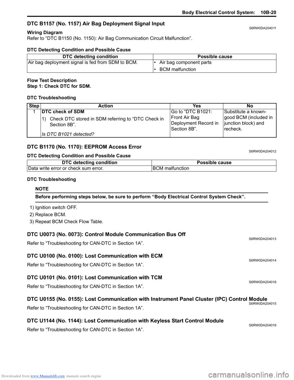
Downloaded from www.Manualslib.com manuals search engine Body Electrical Control System: 10B-20
DTC B1157 (No. 1157) Air Bag Deployment Signal InputS6RW0DA204011
Wiring Diagram
Refer to “DTC B1150 (No. 1150): Air Bag Communication Circuit Malfunction”.
DTC Detecting Condition and Possible Cause
Flow Test Description
Step 1: Check DTC for SDM.
DTC Troubleshooting
DTC B1170 (No. 1170): EEPROM Access ErrorS6RW0DA204012
DTC Detecting Condition and Possible Cause
DTC Troubleshooting
NOTE
Before performing steps below, be sure to perform “Body Electrical Control System Check”.
1) Ignition switch OFF.
2) Replace BCM.
3) Repeat BCM Check Flow Table.
DTC U0073 (No. 0073): Control Module Communication Bus OffS6RW0DA204013
Refer to “Troubleshooting for CAN-DTC in Section 1A”.
DTC U0100 (No. 0100): Lost Communication with ECMS6RW0DA204014
Refer to “Troubleshooting for CAN-DTC in Section 1A”.
DTC U0101 (No. 0101): Lost Communication with TCMS6RW0DA204018
Refer to “Troubleshooting for CAN-DTC in Section 1A”.
DTC U0155 (No. 0155): Lost Communication with Instrument Panel Cluster (IPC) Control ModuleS6RW0DA204015
Refer to “Troubleshooting for CAN-DTC in Section 1A”.
DTC U1144 (No. 1144): Lost Communication with Keyless Start Control ModuleS6RW0DA204016
Refer to “Troubleshooting for CAN-DTC in Section 1A”. DTC detecting condition Possible cause
Air bag deployment signal is fed from SDM to BCM. • Air bag component parts
• BCM malfunction
Step Action Yes No
1DTC check of SDM
1) Check DTC stored in SDM referring to “DTC Check in
Section 8B”.
Is DTC B1021 detected?Go to “DTC B1021:
Front Air Bag
Deployment Record in
Section 8B”.Substitute a known-
good BCM (included in
junction block) and
recheck.
DTC detecting condition Possible cause
Data write error or check sum error. BCM malfunction