Page 1238 of 1556
Downloaded from www.Manualslib.com manuals search engine 9A-71 Wiring Systems:
TCM
WHTRED
717C06
124C01 E01145457195526C016513
ECM
WHT
ABS
Cont.M
APP sensor Throttle position sensor
Throttle sensor
SUB
open close open close open close
open close
MAIN SUB MAIN
Throttle
motor
REDBLUGRNBRNWHTYELREDBLKWHTGRNREDYELBLU
E08
3
18
1
12E1911
6C482
156435234
RW
RW
4142405443454434365135375250E01 C01
(CAN)
(CAN)
BLKGRY
GRN/WHTGRN/YELBRN
B
P/S
Cont.M
"F-3"
RED/BLU
GWGY
IG COIL
#2 IG COIL
#1
BW
Heater fan
switch"A-3"
"E-1"
RB
"E-2"
ORNGRY/RED
GRY/REDRED/BLU
EVAP thermistor
1
3G32
8
ORN
WHT/BLKBLU/WHTORN
E382
G334
BW
Auto
Unit
A/C
pressure
sensorE36
C343
E37110
2
3
BLU/WHTORN
915
WHT/BLKBLU/WHT
Auto A/C
Manual A/C
1
8915
3
I6RW0C910944-03
Page 1242 of 1556
Downloaded from www.Manualslib.com manuals search engine 9A-75 Wiring Systems:
TCM
WHTRED
717C06
4944C0114E013641351227C01212050
ECM
WHT
ABS
Cont.M
APP sensor Throttle position sensor
Throttle sensor
SUB
open close open close open close
open close
MAIN SUB MAIN
Throttle
motor
REDBLUGRNBRNWHTYELREDBLKWHTGRNREDYELBLU
E08
4
19
1
12E1911
6C481
256435234
RW
RW
33414054534544535251565554E01 C01
(CAN)
(CAN)
WHTBLK
GRN/WHTGRN/YELBRN
B
P/S
Cont.M
"F-3"
RED/BLU
GWGY
IG COIL
#2 IG COIL
#1
BW
Mode control
switch"A-3"
"E-1"
19
GRN/BLK
GB
IG COIL
#3
18
GRN
G
IG COIL
#4
RB
"E-2"
ORNGRY/REDRED/BLU
GRY/REDRED/BLU
EVAP thermistor
1
3G32
8
ORN
WHT/BLKBLU/WHTORN
E382
G334
BW
Auto
Unit
A/C
pressure
sensorE36
C343
E3711011
2
3
BLU/WHTORN
915
89
15
WHT/BLKBLU/WHT
Auto A/C
Manual A/C
1
I6RW0C910947-03
Page 1244 of 1556

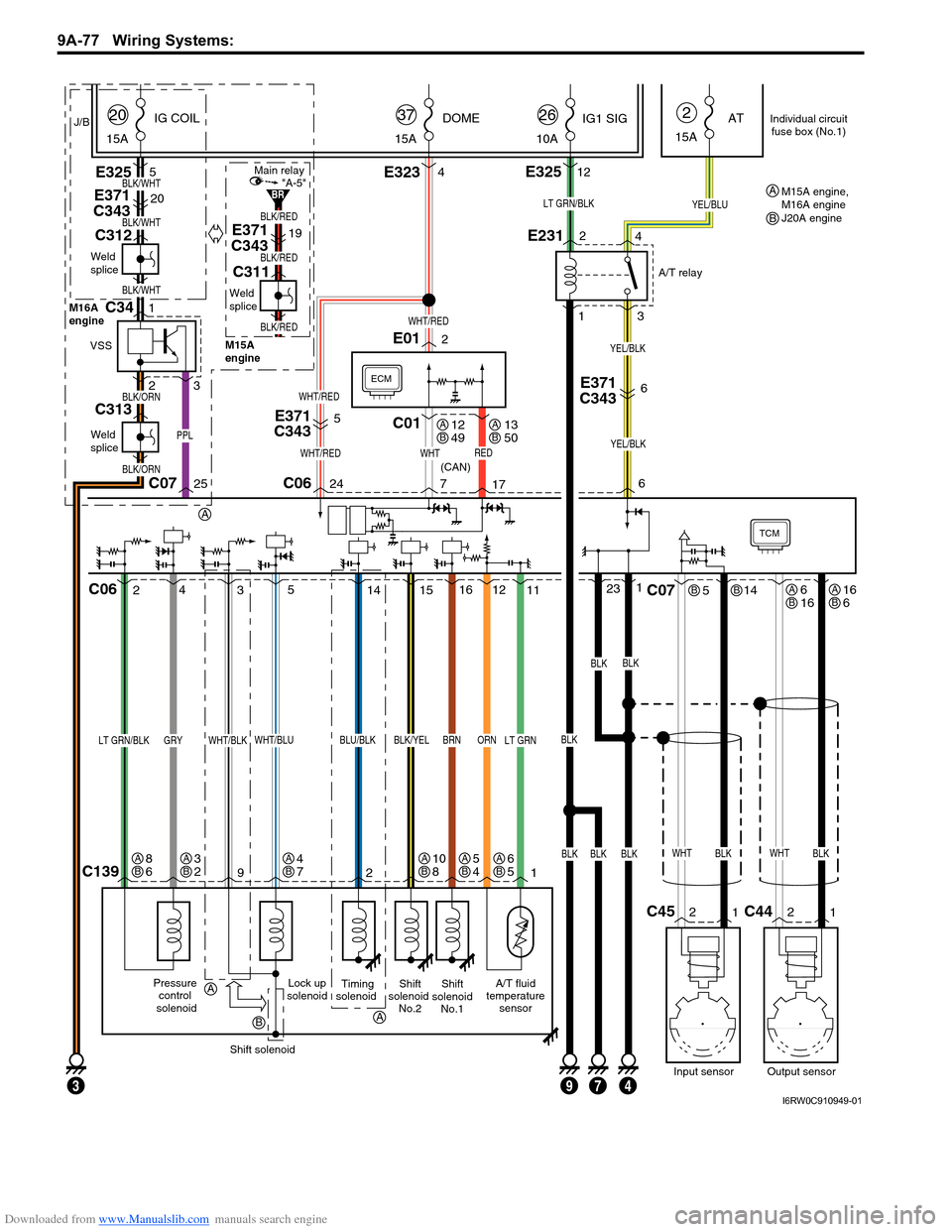
Downloaded from www.Manualslib.com manuals search engine 9A-77 Wiring Systems:
TCM
Lock up
solenoidA/T fluid
temperature
sensorShift
solenoid
No.2Shift
solenoid
No.1
11 12
C1391 2 9
BLK/YELBRNORN
15 4
25
WHT/BLU
Pressure
control
solenoid
LT GRN/BLKGRY
Shift solenoid
LT GRN
ECM
WHTREDWHT/RED
PPL
WHT/RED
BLK/WHT
BLK/RED
BLK/RED
BLK/RED
BLK/WHT
BLK/WHT
5
E371
C343
E371
C34320
E371
C34319
C01
BLKBLKBLK
BLKBLK
E3234E3255
WHT/RED
24 C0625C07717
23116
E012
J/B
15ADOME
37
15AIG COIL
20
15AAT
2
6
3
WHT/BLK
LT GRN/BLK
Timing
solenoid
BLU/BLK
14
WHTBLK
514
2
1C45
Input sensor
C07
WHTBLK
2
1C44
Output sensor
C06
E231
1
3 2
4
YEL/BLU
10AIG1 SIG
26
E32512
BLK
A/T relay
(CAN)
YEL/BLK
7934
E371
C3436
YEL/BLK
Individual circuit
fuse box (No.1)
12
49AB13
50AB
6
16ABBB16
6AB
6
5AB5
4AB4
7AB3
2AB8
6AB10
8AB
A
A
A
B
Weld
splice
M16A
engine
M15A
engine
C312
Weld
splice
C311
BLK/ORN
BLK/ORN
Weld
splice
C313
VSS
1C34
23
"A-5"Main relay
BRM15A engine,
M16A engine
J20A engine A
B
I6RW0C910949-01
Page 1247 of 1556
Downloaded from www.Manualslib.com manuals search engine Wiring Systems: 9A-80
15 7
"D-5"
16 BBG0410
BLU/YEL
BLU/YEL
J/C
G308
G146
1 47 4
Main switch
(Key switch)
RHD Flasher relay
DOME
G2715 15A
37ACC MTR
15A23
228
1
12
HORN
-HAZ
15A39
11
10A
22
WHT/RED
WHT/RED
YEL/REDYEL/BLK
1E37
2
Ambient
temperature
sensor
"B-5" Switch
614
1617125
RED/BLUBRN/YELLT GRN/BLKBRNGRY/WHTGRY/RED
Parking
brake
switchSeat
belt
switch
"C-3"
RBBY
115
RED/BLK
BB
Oil
pressure
switchBrake
fluid
level
switch
GRB
L01 L01E04
10E048
LgBBGWGR
Main switch
"B-5"
Sub switch
"B-5"
Front door
switch
Front door
switch
"D-5"
BRBR
BLK/BLUBLK/RED
BLK/REDBLK/REDBLK/RED
J/B
FF
Rear door
switch
"D-5"
BR
DD
J/CJ/C
L346
L347
AA
J/C
G307
BCM
GRY
J/B side connector (BCM) A
A
I6RW0C910952-02
Page 1251 of 1556
Downloaded from www.Manualslib.com manuals search engine Wiring Systems: 9A-84
38 39
"D-5""D-1"
BLK/BLU
3 AA BBG042
BLU/YEL
BLU/YEL
J/C
G307
1G265
J/C
G308
G146
1 4
Main switch
(Key switch)
DOME
G2715 15A
37ACC
G2725 15A
23
WHT/REDWHT/BLK
WHT/RED
YEL/RED
YEL/RED
YEL/BLK
YEL/BLK
1E37
2
Ambient
temperature
sensor
"B-5" Switch
840
37362726
RED/BLUBRN/YELLT GRN/BLKBRNGRY/WHTGRY/RED
Parking
brake
switchSeat
belt
switch
"C-3"
RBBY
97
RED/BLK
BB
GR
Oil
pressure
switchBrake
fluid
level
switch
Security
option
GRB
G05G0617
PNK
G04
24
GRY/RED
9G0521
LgBBGWGR
Main switch
"B-5"
Sub switch
"B-5"
Front door
switch
"D-3"Switch
Front door
switch
"D-5"
BRBR
BLK/RED
R
12
RED
BLK/BLUBLK/RED
BLK/REDBLK/REDBLK/RED
J/B
FF
Rear door
switch
"D-5"
BR
DD
J/CJ/C
L346
L347
BCM
GRY
E381
G33334
G343
L3761511
I6RW0C910956-01
Page 1273 of 1556
Downloaded from www.Manualslib.com manuals search engine Wiring Systems: 9A-106
C-3 Combination Meter Circuit Diagram (Warning Light)S6RW0D910E021
J/BMTR
10A22
31
Stepper motor and
LED output driver
Voltage regulator
Micro controller
G2716
RED/BLK
516
YB
YEL/BLK
"F-1"
CAN
High Low
WHTWHTRED
RW
10G2419
7
L01
G05
RED/BLUBRN/YEL
L1671
Parking
brake
switch
1
2
A
A
16
BLK/ORN
BLK/ORN
J/C
L348B
B
J/C
G309
Seat
belt
switch
Oil
pressure
switch
J/B
13
Y
YEL
"D-4"
ILL cancel
switch
E371
C3437
G343
L37693G333
E38156
GRY
GRY
1C162
RED/BLK
RED/BLUBRN/YELGRYRED/BLK
E1831
Brake
fluid
level
switch
2
71114
BLK
BLK
BLK
9
BLKBLK
W
WHTRED
1
2
A
AB
B
J/C
G311
RBGBYRB
BCM
"A-10"
4WD
Cont.M
Interface circuit
RED
6
R"A-10"
4WD
Cont.M
(CAN) (CAN) (CAN)
IF EQPD
Except Taiwan
Taiwan
Without seat heater
With seat heater A
A
B
L170
L281C
D
G04
G05A
BE04
G05A
B
BCD
B
6
8AB14
40AB11
9AB5
7AB2
3AB4
1AB
I6RW0D910915-01
Page 1329 of 1556

Downloaded from www.Manualslib.com manuals search engine Lighting Systems: 9B-10
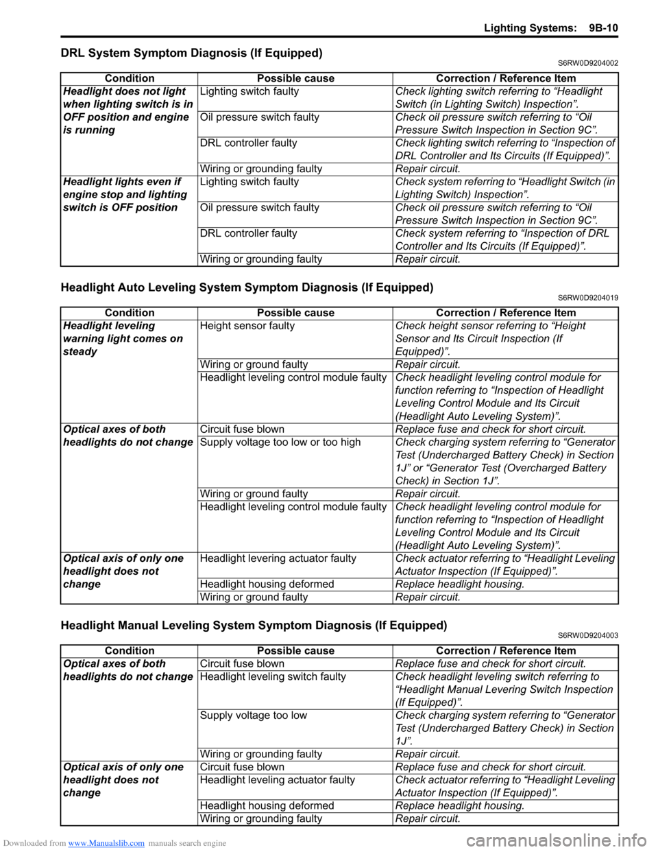
DRL System Symptom Diagnosis (If Equipped)S6RW0D9204002
Headlight Auto Leveling System Symptom Diagnosis (If Equipped)S6RW0D9204019
Headlight Manual Leveling System Symptom Diagnosis (If Equipped)S6RW0D9204003
Condition Possible cause Correction / Reference Item
Headlight does not light
when lighting switch is in
OFF position and engine
is runningLighting switch faultyCheck lighting switch referring to “Headlight
Switch (in Lighting Switch) Inspection”.
Oil pressure switch faultyCheck oil pressure switch referring to “Oil
Pressure Switch Inspection in Section 9C”.
DRL controller faultyCheck lighting switch referring to “Inspection of
DRL Controller and Its Circuits (If Equipped)”.
Wiring or grounding faultyRepair circuit.
Headlight lights even if
engine stop and lighting
switch is OFF positionLighting switch faultyCheck system referring to “Headlight Switch (in
Lighting Switch) Inspection”.
Oil pressure switch faultyCheck oil pressure switch referring to “Oil
Pressure Switch Inspection in Section 9C”.
DRL controller faultyCheck system referring to “Inspection of DRL
Controller and Its Circuits (If Equipped)”.
Wiring or grounding faultyRepair circuit.
Condition Possible cause Correction / Reference Item
Headlight leveling
warning light comes on
steadyHeight sensor faultyCheck height sensor referring to “Height
Sensor and Its Circuit Inspection (If
Equipped)”.
Wiring or ground faultyRepair circuit.
Headlight leveling control module faultyCheck headlight leveling control module for
function referring to “Inspection of Headlight
Leveling Control Module and Its Circuit
(Headlight Auto Leveling System)”.
Optical axes of both
headlights do not changeCircuit fuse blownReplace fuse and check for short circuit.
Supply voltage too low or too highCheck charging system referring to “Generator
Test (Undercharged Battery Check) in Section
1J” or “Generator Test (Overcharged Battery
Check) in Section 1J”.
Wiring or ground faultyRepair circuit.
Headlight leveling control module faultyCheck headlight leveling control module for
function referring to “Inspection of Headlight
Leveling Control Module and Its Circuit
(Headlight Auto Leveling System)”.
Optical axis of only one
headlight does not
changeHeadlight levering actuator faultyCheck actuator referring to “Headlight Leveling
Actuator Inspection (If Equipped)”.
Headlight housing deformedReplace headlight housing.
Wiring or ground faultyRepair circuit.
Condition Possible cause Correction / Reference Item
Optical axes of both
headlights do not changeCircuit fuse blownReplace fuse and check for short circuit.
Headlight leveling switch faultyCheck headlight leveling switch referring to
“Headlight Manual Levering Switch Inspection
(If Equipped)”.
Supply voltage too lowCheck charging system referring to “Generator
Test (Undercharged Battery Check) in Section
1J”.
Wiring or grounding faultyRepair circuit.
Optical axis of only one
headlight does not
changeCircuit fuse blownReplace fuse and check for short circuit.
Headlight leveling actuator faultyCheck actuator referring to “Headlight Leveling
Actuator Inspection (If Equipped)”.
Headlight housing deformedReplace headlight housing.
Wiring or grounding faultyRepair circuit.
Page 1332 of 1556

Downloaded from www.Manualslib.com manuals search engine 9B-13 Lighting Systems:
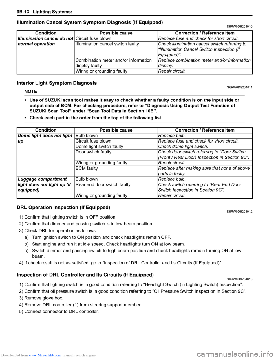
Illumination Cancel System Symptom Diagnosis (If Equipped)S6RW0D9204010
Interior Light Symptom DiagnosisS6RW0D9204011
NOTE
• Use of SUZUKI scan tool makes it easy to check whether a faulty condition is on the input side or
output side of BCM. For checking procedure, refer to “Diagnosis Using Output Test Function of
SUZUKI Scan Tool” under “Scan Tool Data in Section 10B”.
• Check each part in the order from the top of the following list.
DRL Operation Inspection (If Equipped)S6RW0D9204012
1) Confirm that lighting switch is in OFF position.
2) Confirm that dimmer and passing switch is in low beam position.
3) Check DRL for operation as follows.
a) Turn ignition switch to ON position and check headlights remain OFF.
b) Start engine and run it at idle speed. Check headlights turn ON at low beam.
c) Switch dimmer and passing switch to high beam position and check headlights remain turning ON at low
beam.
4) If check result is not as satisfied, go to “Inspection of DRL Controller and Its Circuits (If Equipped)”.
Inspection of DRL Controller and Its Circuits (If Equipped)S6RW0D9204013
1) Confirm that lighting switch is in good condition referring to “Headlight Switch (in Lighting Switch) Inspection”.
2) Confirm that oil pressure switch is in good condition referring to “Oil Pressure Switch Inspection in Section 9C”.
3) Remove glove box.
4) Remove DRL controller (1) from steering support member.
5) Connect connector to DRL controller.Condition Possible cause Correction / Reference Item
Illumination cancel do not
normal operationCircuit fuse blownReplace fuse and check for short circuit.
Illumination cancel switch faultyCheck illumination cancel switch referring to
“Illumination Cancel Switch Inspection (If
Equipped)”.
Combination meter and/or information
display faultyReplace combination meter and/or information
display.
Wiring or grounding faultyRepair circuit.
Condition Possible cause Correction / Reference Item
Dome light does not light
upBulb blownReplace bulb.
Circuit fuse blownReplace fuse and check for short circuit.
Dome light switch faultyCheck dome light switch.
Door switch faultyCheck door switch referring to “Door Switch
(Front / Rear Door) Inspection in Section 9C”.
Wiring or grounding faultyRepair circuit.
BCM faultyReplace after making sure that none of above
parts is faulty.
Luggage compartment
light does not light up (if
equipped)Bulb blownReplace bulb.
Rear end door switch faultyCheck switch referring to “Rear End Door
Switch Inspection in Section 9C”.
Wiring or grounding faultyRepair circuit.