2006 SUZUKI SX4 battery
[x] Cancel search: batteryPage 423 of 1556

Downloaded from www.Manualslib.com manuals search engine Charging System: 1J-9
Generator Dismounting and RemountingS6RW0D1A06003
1) Disconnect negative cable at battery.
2) Remove right side drive shaft referring to “Front Drive Shaft Assembly Removal and Installation in Section 3A”
3) Dismount in numerical order as shown in figure.
4) Reverse dismounting procedure for remounting.
I6RW0D1A0004-01
1. “B” terminal nut 5. Generator pivot bolt : 25 N⋅m (2.5 kgf-m, 18.0 lb-ft)
2. “B” terminal wire 6. Generator drive belt : 50 N⋅m (5.0 kgf-m, 36.0 lb-ft)
3. Connector 7. Generator
4. Generator bracket bolt : 5.0 N⋅m (0.5 kg⋅m, 4.0 lb-ft)
Page 427 of 1556

Downloaded from www.Manualslib.com manuals search engine Charging System: 1J-13
Specifications
Charging System SpecificationsS6RW0D1A07003
Battery
NOTE
The battery used in each vehicle is one of the following two types, depending on specification.
Battery
: 46B24R (40.6AH/5HR), 55B24R (42.5AH/5HR) 12V
Generator
Tightening Torque SpecificationsS6RW0D1A07004
NOTE
The specified tightening torque is also described in the following.
“Generator Dismounting and Remounting”
“Generator Components”
Reference:
For the tightening torque of fastener not specified in this section, refer to “Fasteners Information in Section 0A”. Battery type 46B24R 55B24R
Rated capacity AH/5HR, 12 Volts 40.6 42.5
Electrolyte L (US / lmp pt.) — 2.8 (5.92 / 4.93)
Type 70 A type
Rated voltage 12 V
Nominal output 70 A
Permissible max. speed 18,000 r/min.
No-load speed 1020 r/min. (rpm)
Regulated voltage 14.2 – 14.8 V (Hi), 12.5 – 13.1 V (Lo)
Exposed brush length Standard: 10.5 mm (0.41 in.)
Limit: 1.5 mm (0.05 in.)
Permissible ambient temperature –30 to 90 °C (–22 to 194 °F)
Polarity Negative ground
Rotation Clockwise viewed from pulley side
Fastening partTightening torque
Note
N⋅mkgf-mlb-ft
Generator bracket bolt 25 2.5 18.0�)
Generator pivot bolt 50 5.0 36.0�)
Generator adjusting bolt
Tighten 7.0 0.7 5.0by the specified
procedure. �)
Page 430 of 1556

Downloaded from www.Manualslib.com manuals search engine 1K-3 Exhaust System:
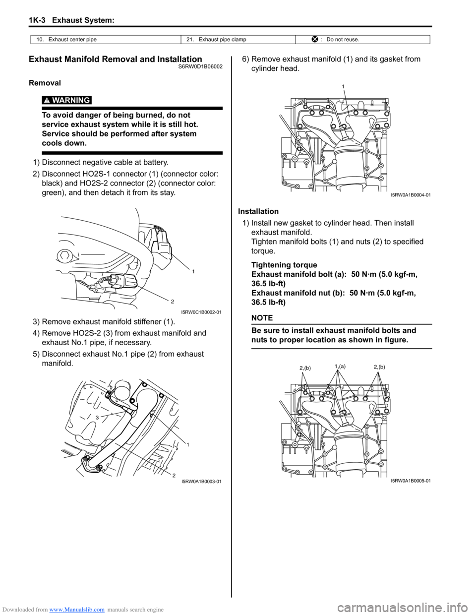
Exhaust Manifold Removal and InstallationS6RW0D1B06002
Removal
WARNING!
To avoid danger of being burned, do not
service exhaust system while it is still hot.
Service should be performed after system
cools down.
1) Disconnect negative cable at battery.
2) Disconnect HO2S-1 connector (1) (connector color:
black) and HO2S-2 connector (2) (connector color:
green), and then detach it from its stay.
3) Remove exhaust manifold stiffener (1).
4) Remove HO2S-2 (3) from exhaust manifold and
exhaust No.1 pipe, if necessary.
5) Disconnect exhaust No.1 pipe (2) from exhaust
manifold.6) Remove exhaust manifold (1) and its gasket from
cylinder head.
Installation
1) Install new gasket to cylinder head. Then install
exhaust manifold.
Tighten manifold bolts (1) and nuts (2) to specified
torque.
Tightening torque
Exhaust manifold bolt (a): 50 N·m (5.0 kgf-m,
36.5 lb-ft)
Exhaust manifold nut (b): 50 N·m (5.0 kgf-m,
36.5 lb-ft)
NOTE
Be sure to install exhaust manifold bolts and
nuts to proper location as shown in figure.
10. Exhaust center pipe 21. Exhaust pipe clamp : Do not reuse.
2
1
I5RW0C1B0002-01
2 3
1
I5RW0A1B0003-01
1
I5RW0A1B0004-01
1,(a)2,(b)2,(b)
I5RW0A1B0005-01
Page 431 of 1556

Downloaded from www.Manualslib.com manuals search engine Exhaust System: 1K-4
2) Install new seal ring and connect exhaust No.1 pipe
(1) to exhaust manifold.
Tighten pipe fasteners to specified torque.
Tightening torque
Exhaust No.1 pipe bolt (a): 50 N·m (5.0 kgf-m,
36.5 lb-ft)
3) Install exhaust manifold stiffener (2).
Tighten exhaust manifold stiffener bolts to specified
torque.
Tightening torque
Exhaust manifold stiffener bolt (b): 50 N·m (5.0
kgf-m, 36.5 lb-ft)
4) Install new seal ring and connect exhaust No.1 pipe
(1) to exhaust No.2 pipe. Tighten pipe fasteners to
specified torque.
Tightening torque
Exhaust No.2 pipe bolt (c): 43 N·m (4.3 kgf-m,
31.0 lb-ft)
5) Install HO2S-2 (3) and tighten HO2S-2 bracket bolt
(4) referring to “Exhaust System Components”, if
removed.
NOTE
Be sure to identify HO2S-1 and HO2S-2 by its
connector color referring to “Exhaust System
Components”.
6) Connect HO2S-1 connector (1) (connector color:
black) and HO2S-2 connector (2) (connector color:
green), and then fit coupler to bracket securely.
7) Connect negative cable at battery.
8) Check exhaust system for exhaust gas leakage.
Exhaust Pipe and Muffler Removal and
Installation
S6RW0D1B06003
For replacement of exhaust pipe, be sure to hoist vehicle
and observe WARNING under “Exhaust System
Components” and the following.
CAUTION!
Exhaust manifold have three way catalytic
converter in it, it should not be exposed to
any impulse.
Be careful not to drop it or hit it against
something.
• Tighten bolts and nuts to specified torque when
reassembling. Refer to “Exhaust System
Components”.
• After installation, start engine and check each joint of
exhaust system for leakage.
1 (c)3 4
(a)
(b)
2
I5RW0A1B0006-01
2
1
I5RW0C1B0002-01
Page 455 of 1556

Downloaded from www.Manualslib.com manuals search engine Front Suspension: 2B-18
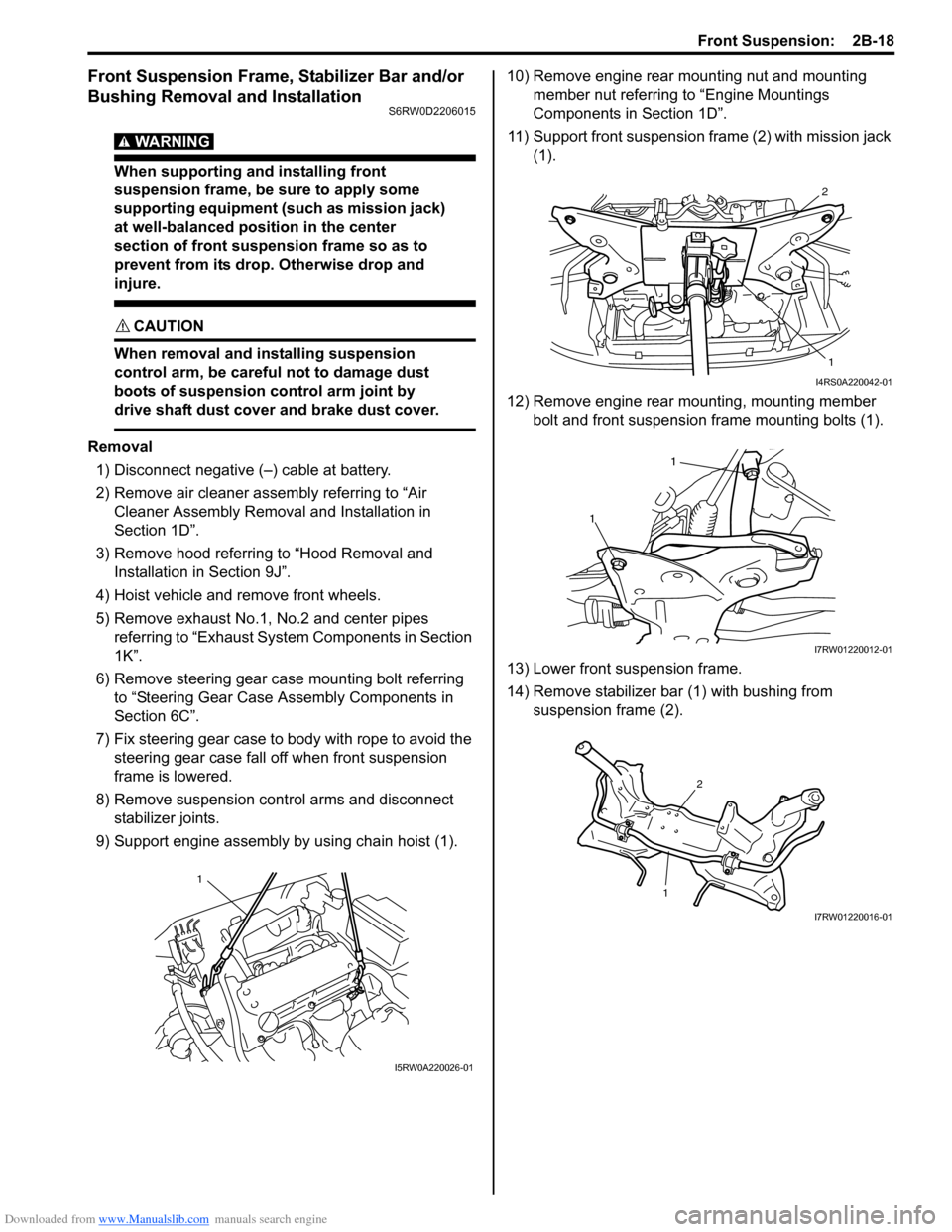
Front Suspension Frame, Stabilizer Bar and/or
Bushing Removal and Installation
S6RW0D2206015
WARNING!
When supporting and installing front
suspension frame, be sure to apply some
supporting equipment (such as mission jack)
at well-balanced position in the center
section of front suspension frame so as to
prevent from its drop. Otherwise drop and
injure.
CAUTION!
When removal and installing suspension
control arm, be careful not to damage dust
boots of suspension control arm joint by
drive shaft dust cover and brake dust cover.
Removal
1) Disconnect negative (–) cable at battery.
2) Remove air cleaner assembly referring to “Air
Cleaner Assembly Removal and Installation in
Section 1D”.
3) Remove hood referring to “Hood Removal and
Installation in Section 9J”.
4) Hoist vehicle and remove front wheels.
5) Remove exhaust No.1, No.2 and center pipes
referring to “Exhaust System Components in Section
1K”.
6) Remove steering gear case mounting bolt referring
to “Steering Gear Case Assembly Components in
Section 6C”.
7) Fix steering gear case to body with rope to avoid the
steering gear case fall off when front suspension
frame is lowered.
8) Remove suspension control arms and disconnect
stabilizer joints.
9) Support engine assembly by using chain hoist (1).10) Remove engine rear mounting nut and mounting
member nut referring to “Engine Mountings
Components in Section 1D”.
11) Support front suspension frame (2) with mission jack
(1).
12) Remove engine rear mounting, mounting member
bolt and front suspension frame mounting bolts (1).
13) Lower front suspension frame.
14) Remove stabilizer bar (1) with bushing from
suspension frame (2).
1
I5RW0A220026-01
2
1
I4RS0A220042-01
1
1
I7RW01220012-01
12
I7RW01220016-01
Page 457 of 1556

Downloaded from www.Manualslib.com manuals search engine Front Suspension: 2B-20
12) Install exhaust No.1, No.2 and center pipe referring
to “Exhaust System Components in Section 1K”.
13) Install wheel and tighten nut to specified torque.
Tightening torque
Wheel nut: 85 N·m (8.5 kgf-m, 61.5 lb-ft)
14) Install air cleaner assembly referring to “Air Cleaner
Assembly Removal and Installation in Section 1D”.
15) Install hood referring to “Hood Removal and
Installation in Section 9J”.
16) Lower hoist and vehicle in unloaded condition,
tighten suspension control arm bolts to specified
torque.
Tightening torque
Suspension control arm bolt: 95 N·m (9.5 kgf-m,
69.0 lb-ft)
17) Connect negative (–) cable at battery.
18) Confirm front wheel alignment referring to “Front
Wheel Alignment Inspection and Adjustment”.
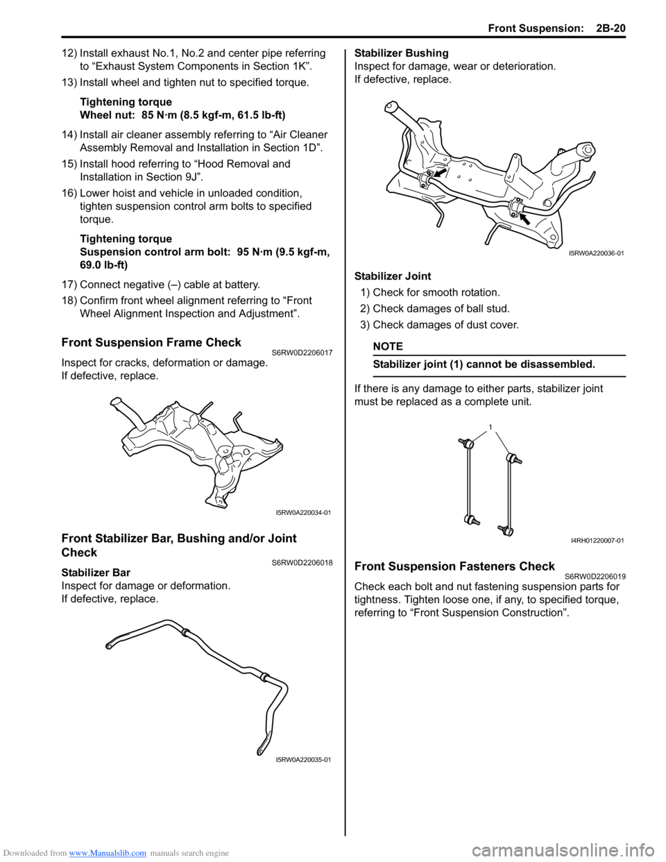
Front Suspension Frame CheckS6RW0D2206017
Inspect for cracks, deformation or damage.
If defective, replace.
Front Stabilizer Bar, Bushing and/or Joint
Check
S6RW0D2206018
Stabilizer Bar
Inspect for damage or deformation.
If defective, replace.Stabilizer Bushing
Inspect for damage, wear or deterioration.
If defective, replace.
Stabilizer Joint
1) Check for smooth rotation.
2) Check damages of ball stud.
3) Check damages of dust cover.
NOTE
Stabilizer joint (1) cannot be disassembled.
If there is any damage to either parts, stabilizer joint
must be replaced as a complete unit.
Front Suspension Fasteners CheckS6RW0D2206019
Check each bolt and nut fastening suspension parts for
tightness. Tighten loose one, if any, to specified torque,
referring to “Front Suspension Construction”.
I5RW0A220034-01
I5RW0A220035-01
I5RW0A220036-01
1
I4RH01220007-01
Page 498 of 1556

Downloaded from www.Manualslib.com manuals search engine 3B-1 Differential:
Driveline / Axle
Differential
Precautions
Precaution for Rear Differential Oil LeakageS6RW0D3200001
Whenever vehicle is hoisted for any other service work than oil change, also be sure to check for oil leakage.
Precautions in Diagnosing TroubleS6RW0D3200002
• Do not disconnect the following parts before confirming diagnostic information (DTC, etc.) stored in 4WD control
module memory. These actions will erase memorized information in 4WD control module memory.
– Disconnection of coupler from 4WD control module
– Disconnection of battery cable from battery
– Disconnection of ground wire harness of 4WD control module
– Disconnect main fuse from fuse box
• Diagnostic information stored in 4WD control module memory can be cleared as well as checked by using SUZUKI
scan tool. Before using scan tool, read its Operator’s (Instruction) Manual carefully to have good understanding as
to what functions are available and how to use it.
• Be sure to read “Precautions for Electrical Circuit Service:” before inspection and observe what is written there.
Page 508 of 1556

Downloaded from www.Manualslib.com manuals search engine 3B-11 Differential:
Visual InspectionS6RW0D3204004
Check the following parts and systems visually.
DTC CheckS6RW0D3204005
1) Turn ignition switch to OFF position.
2) Connect SUZUKI scan tool to data link connector
(DLC) (1) located on underside of instrument panel.
Special tool
(A): SUZUKI scan tool
3) Turn ignition switch to ON position.
4) Read DTC according to instructions displayed on
SUZUKI scan tool and print it or write it down. Refer
to SUZUKI scan tool operator’s manual for further
details.
If communication between SUZUKI scan tool and
4WD control module is not possible, check if
SUZUKI scan tool is communicable by connecting it
to 4WD control module in another vehicle. If
communication is possible in this case, SUZUKI
scan tool is in good condition. Then check data link
connector and serial data line (circuit) in the vehicle
with which communication was not possible.
5) After completing the check, turn ignition switch OFF
and disconnect SUZUKI scan tool from data link
connector (DLC).
DTC ClearanceS6RW0D3204006
1) Turn ignition switch to OFF position.
2) Connect SUZUKI scan tool to data link connector
(DLC) (1) located on underside of instrument panel.
Special tool
(A): SUZUKI scan tool
3) Turn ignition switch to ON position.
4) Erase DTC according to instructions displayed on
SUZUKI scan tool. Refer to SUZUKI scan tool
operator’s manual for further details.
5) After completing clearance, turn ignition switch OFF
and disconnect SUZUKI scan tool from data link
connector (DLC).
6) Perform “DTC Check” and confirm that NO CODES
is displayed.
NOTE
DTC stored in 4WD control module memory
are also cleared in the following cases. Be
careful not to clear them before keeping their
record.
• When power to 4WD control module is cut
off (by disconnecting battery cable,
removing fuse or disconnecting 4WD
control module connectors).
• When the same malfunction (DTC) is not
detected again during 40 engine warm-up
cycles.
Inspection Item Referring
• Rear differential oil ---- level, leakage “Rear Differential Oil Change”
• Transfer gear oil ---- level, leakage “Transfer Oil Change in Section 3C”
• Manual transmission oil ---- level, leakage “Manual Transaxle Oil Change in Section 5B”
• Rear differential mounting(s) ---- wear and looseness
• Fuses ---- burning
• Battery ---- fluid level, corrosion of terminal “Battery Inspection in Section 1J”
• Connectors of electric wire harness ---- disconnection,
friction“Intermittent and Poor Connection Inspection in Section
00”
• Other parts that can be checked visually
1(A)I5RW0A320008-011(A)I5RW0A320008-01