2006 SUZUKI SWIFT reversing
[x] Cancel search: reversingPage 422 of 1496
Downloaded from www.Manualslib.com manuals search engine 1J-12 Charging System:
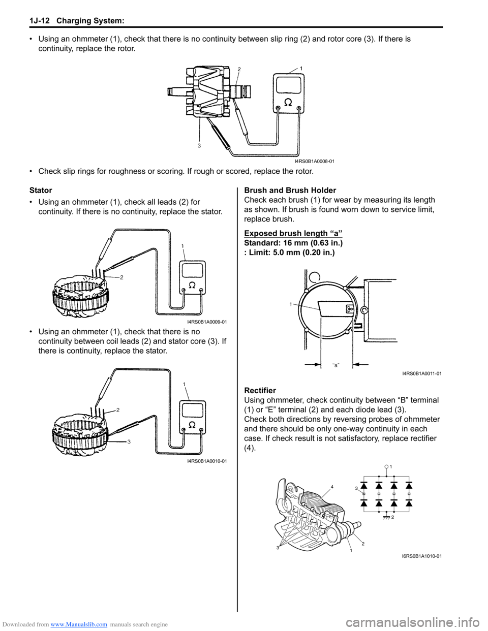
• Using an ohmmeter (1), check that there is no continuity between slip ring (2) and rotor core (3). If there is
continuity, replace the rotor.
• Check slip rings for roughness or scoring. If rough or scored, replace the rotor.
Stator
• Using an ohmmeter (1), check all leads (2) for continuity. If there is no co ntinuity, replace the stator.
• Using an ohmmeter (1), check that there is no continuity between coil leads (2) and stator core (3). If
there is continuity, replace the stator. Brush and Brush Holder
Check each brush (1) for wear by measuring its length
as shown. If brush is found worn down to service limit,
replace brush.
Exposed brush length “a”
Standard: 16 mm (0.63 in.)
: Limit: 5.0 mm (0.20 in.)
Rectifier
Using ohmmeter, check continuity between “B” terminal
(1) or “E” terminal (2) and each diode lead (3).
Check both directions by reversing probes of ohmmeter
and there should be only one-way continuity in each
case. If check result is not satisfactory, replace rectifier
(4).
I4RS0B1A0008-01
I4RS0B1A0009-01
I4RS0B1A0010-01
I4RS0B1A0011-01
1
1
3 3
2
2
4
I6RS0B1A1010-01
Page 438 of 1496
Downloaded from www.Manualslib.com manuals search engine 2B-5 Front Suspension:
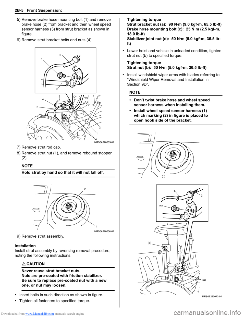
5) Remove brake hose mounting bolt (1) and remove brake hose (2) from bracket and then wheel speed
sensor harness (3) from strut bracket as shown in
figure.
6) Remove strut bracket bolts and nuts (4).
7) Remove strut rod cap.
8) Remove strut nut (1), and remove rebound stopper (2).
NOTE
Hold strut by hand so th at it will not fall off.
9) Remove strut assembly.
Installation
Install strut assembly by reversing removal procedure,
noting the following instructions.
CAUTION!
Never reuse strut bracket nuts.
Nuts are pre-coated with friction stabilizer.
Be sure to replace pre-coated nut with a new
one, or nut may loosen.
• Insert bolts in such direction as shown in figure.
• Tighten all fasteners to specified torque. Tightening torque
Strut bracket nut (a): 90 N·m (9.0 kgf-m, 65.5 lb-ft)
Brake hose mounting bolt (c): 25 N·m (2.5 kgf-m,
18.0 lb-ft)
Stabilizer joint nut (d): 50 N·m (5.0 kgf-m, 36.5 lb-
ft)
• Lower hoist and vehicle in unloaded condition, tighten strut nut (b) to specified torque.
Tightening torque
Strut nut (b): 50 N·m (5.0 kgf-m, 36.5 lb-ft)
• Install windshield wiper arms with blades referring to
“Windshield Wiper Removal and Installation in
Section 9D”.
NOTE
• Don’t twist brake hose and wheel speed sensor harness when installing them.
• Install wheel speed sensor harness (1) which marking (2) in figure is placed to
open hook side of the bracket.
1 3
2
2
1
4
4
3
I4RS0A220005-01
2
1
I4RS0A220006-01
(d) (a)
(b)
(c)
1
2
I4RS0B220012-01
Page 465 of 1496
Downloaded from www.Manualslib.com manuals search engine Rear Suspension: 2C-11
Installation
Install wheel hub by reversing removal procedure noting
the following instructions.
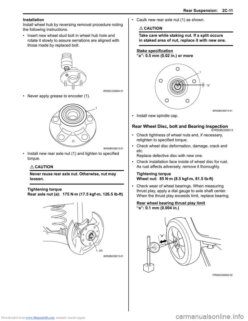
• Insert new wheel stud bolt in wheel hub hole and rotate it slowly to assure serrations are aligned with
those made by replaced bolt.
• Never apply grease to encoder (1).
• Install new rear axle nut (1) and tighten to specified torque.
CAUTION!
Never reuse rear axle nut. Otherwise, nut may
loosen.
Tightening torque
Rear axle nut (a): 175 N·m (17.5 kgf-m, 126.5 lb-ft) • Caulk new rear axle nut (1) as shown.
CAUTION!
Take care while staking nut. If a split occurs
in staked area of nut,
replace it with new one.
Stake specification
“a”: 0.5 mm (0.02 in.) or more
• Install new spindle cap.
Rear Wheel Disc, bolt and Bearing InspectionS7RS0B2306013
• Check tightness of wheel nuts and, if necessary, retighten to specified torque.
• Check wheel disc deformation, damage, crack and etc.
Replace defective disc with new one.
• Check installation face insi de of wheel disc for rust.
As rust affects adversely, remove it thoroughly.
Tightening torque
Wheel nut: 85 N·m (8.5 kgf-m, 61.5 lb-ft)
• Check wear of wheel bearings. When measuring thrust play, apply a dial gauge to axle shaft center.
When the thrust play exce eds limit, replace bearing.
Rear wheel bearing thrust play
limit
“a”: 0.1 mm (0.004 in.)
I6RS0C230004-01
1
I6RS0B230012-01
1, (a)
I6RS0B230013-01
1
“a”
I6RS0B230014-01
I7RS0A230002-02
Page 483 of 1496
Downloaded from www.Manualslib.com manuals search engine Drive Shaft / Axle: 3A-5
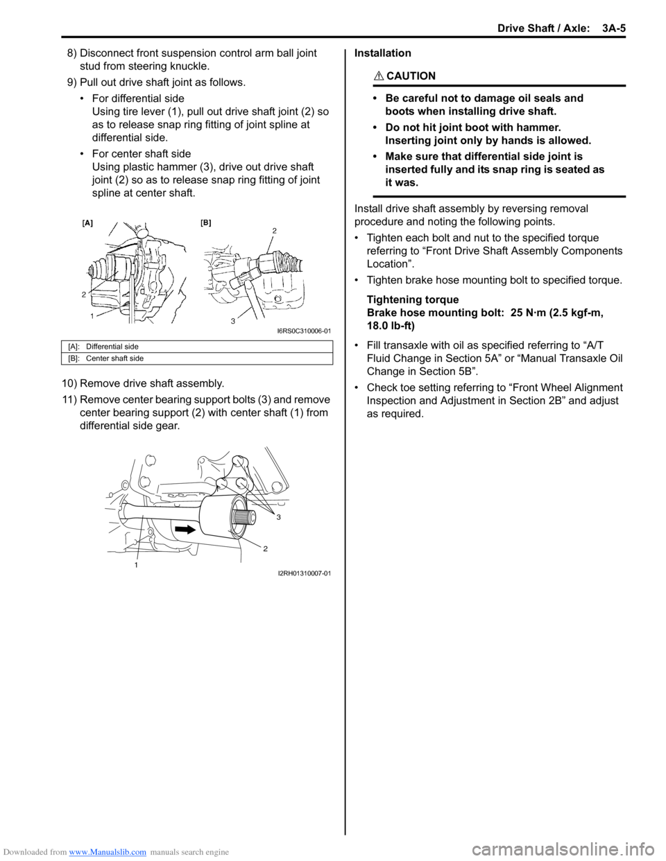
8) Disconnect front suspension control arm ball joint
stud from steering knuckle.
9) Pull out drive shaft joint as follows. • For differential sideUsing tire lever (1), pull out drive shaft joint (2) so
as to release snap ring fitting of joint spline at
differential side.
• For center shaft side Using plastic hammer (3), drive out drive shaft
joint (2) so as to release snap ring fitting of joint
spline at center shaft.
10) Remove drive shaft assembly. 11) Remove center bearing support bolts (3) and remove center bearing support (2) with center shaft (1) from
differential side gear. Installation
CAUTION!
• Be careful not to damage oil seals and
boots when installing drive shaft.
• Do not hit joint boot with hammer. Inserting joint only by hands is allowed.
• Make sure that differential side joint is inserted fully and its snap ring is seated as
it was.
Install drive shaft assemb ly by reversing removal
procedure and noting the following points.
• Tighten each bolt and nut to the specified torque referring to “Front Drive Shaft Assembly Components
Location”.
• Tighten brake hose mounting bolt to specified torque.
Tightening torque
Brake hose mounting bolt: 25 N·m (2.5 kgf-m,
18.0 lb-ft)
• Fill transaxle with oil as sp ecified referring to “A/T
Fluid Change in Section 5A” or “Manual Transaxle Oil
Change in Section 5B”.
• Check toe setting referring to “Front Wheel Alignment Inspection and Adjustment in Section 2B” and adjust
as required.
[A]: Differential side
[B]: Center shaft side
I6RS0C310006-01
3
2
1I2RH01310007-01
Page 492 of 1496
Downloaded from www.Manualslib.com manuals search engine 3A-14 Drive Shaft / Axle:
Center Shaft and Center Bearing Support
Disassembly and Reassembly
S7RS0B3106005
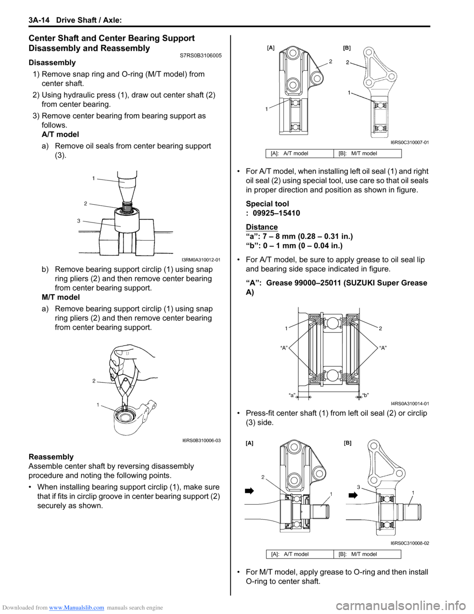
Disassembly1) Remove snap ring and O-ring (M/T model) from center shaft.
2) Using hydraulic press (1), draw out center shaft (2) from center bearing.
3) Remove center bearing from bearing support as follows.
A/T model
a) Remove oil seals from center bearing support (3).
b) Remove bearing support circlip (1) using snap ring pliers (2) and then remove center bearing
from center bearing support.
M/T model
a) Remove bearing support circlip (1) using snap ring pliers (2) and then remove center bearing
from center bearing support.
Reassembly
Assemble center shaft by reversing disassembly
procedure and noting the following points.
• When installing bearing support circlip (1), make sure
that if fits in circlip groove in center bearing support (2)
securely as shown. • For A/T model, when installing
left oil seal (1) and right
oil seal (2) using special tool, use care so that oil seals
in proper direction and position as shown in figure.
Special tool
: 09925–15410
Distance
“a”: 7 – 8 mm (0.28 – 0.31 in.)
“b”: 0 – 1 mm (0 – 0.04 in.)
• For A/T model, be sure to apply grease to oil seal lip and bearing side space indicated in figure.
“A”: Grease 99000–25011 (SUZUKI Super Grease
A)
• Press-fit center shaft (1) from left oil seal (2) or circlip
(3) side.
• For M/T model, apply grease to O-ring and then install O-ring to center shaft.
I3RM0A310012-01
I6RS0B310006-03
[A]: A/T model [B]: M/T model
[A]: A/T model [B]: M/T model
I6RS0C310007-01
12
“A” “A”
“a” “b”
I4RS0A310014-01
I6RS0C310008-02
Page 538 of 1496
Downloaded from www.Manualslib.com manuals search engine 4D-3 Parking Brake:
6) Release parking brake lever and then make sure that there is no drag in rear wheel.
If there is, repeats go to step 2).
7) Make sure that the number of notch is between 4 and 9 when operating parking brake lever.
8) If the number of notch is not between 4 and 9, replace parking brake cable and/or inspect rear
brake caliper.
Parking brake stroke
When lever is pulled up at 200 N (20kg, 44lbs) : 4
to 9 notches
Parking Brake Cable Removal and InstallationS7RS0B4406002
Removal
NOTE
When it is necessary to remove both right
and left parking brake cables, repeat below
steps 2) and 5) on right and left wheels.
1) Hoist vehicle.
2) Remove wheel.
3) Disconnect parking brake cable from equalizer (parking brake lever) and clamps.
4) Disconnect parking brake cable from lever referring to “Rear Disc Brake Caliper Removal and Installation
in Section 4C”.
5) Remove parking brake cable and parking cable bracket.
Installation
Install it by reversing removal procedure, noting the
following points.
• Install clamps properly referring to “Parking Brake Cable Construction”.
• Tighten bolts and nuts to specified torque referring to “Parking Brake Cable Construction”.
Tightening torque
Parking brake lever bolt: 25 N·m (2.5 kgf-m, 18.0
lb-ft)
Parking cable clamp bolt: 11 N·m (1.1 kgf-m, 8.0
lb-ft)
Parking cable bracket bolt: 25 N·m (2.5 kgf-m,
18.0 lb-ft)
• Adjust parking brake cable. Refer to “Parking Brake Inspection and Adjustment”.
• Check brake disc for dragging and brake system for proper performance. Brake test should be performed.
Parking Brake Lever Removal and InstallationS7RS0B4406003
Removal
1) Remove console box.
2) Block vehicle wheels and release parking brake lever.
3) Disconnect lead wire of parking brake switch at coupler.
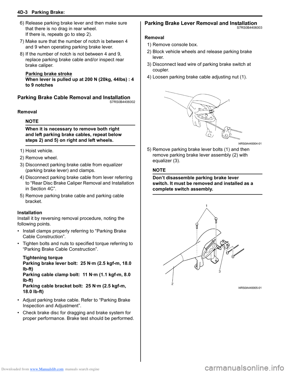
4) Loosen parking brake cable adjusting nut (1).
5) Remove parking brake lever bolts (1) and then remove parking brake lever assembly (2) with
equalizer (3).
NOTE
Don’t disassemble parking brake lever
switch. It must be removed and installed as a
complete switch assembly.
I4RS0A440004-01
I4RS0A440005-01
Page 569 of 1496
Downloaded from www.Manualslib.com manuals search engine ABS: 4E-30
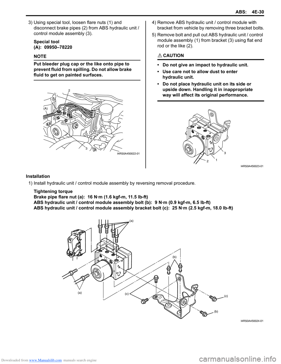
3) Using special tool, loosen flare nuts (1) and disconnect brake pipes (2) from ABS hydraulic unit /
control module assembly (3).
Special tool
(A): 09950–78220
NOTE
Put bleeder plug cap or the like onto pipe to
prevent fluid from spilli ng. Do not allow brake
fluid to get on painted surfaces.
4) Remove ABS hydraulic unit / control module with
bracket from vehicle by removing three bracket bolts.
5) Remove bolt and pull out ABS hydraulic unit / control module assembly (1) from bracket (3) using flat end
rod or the like (2).
CAUTION!
• Do not give an impact to hydraulic unit.
• Use care not to allow dust to enter hydraulic unit.
• Do not place hydraulic unit on its side or upside down. Handling it in inappropriate
way will affect its original performance.
Installation
1) Install hydraulic unit / control module assembly by reversing removal procedure.
Tightening torque
Brake pipe flare nut (a): 16 N·m (1.6 kgf-m, 11.5 lb-ft)
ABS hydraulic unit / control module assembly bolt (b): 9 N·m (0.9 kgf-m, 6.5 lb-ft)
ABS hydraulic unit / control module assembly bracket bolt (c): 25 N·m (2.5 kgf-m, 18.0 lb-ft)
3
2
1
(A)
I4RS0A450022-01
1
3
2
I4RS0A450023-01
(a) (a)(c)
(c)
(b)
(b)
I4RS0A450024-01
Page 571 of 1496
Downloaded from www.Manualslib.com manuals search engine ABS: 4E-32
Front Wheel Speed Sensor Removal and
Installation
S7RS0B4506006
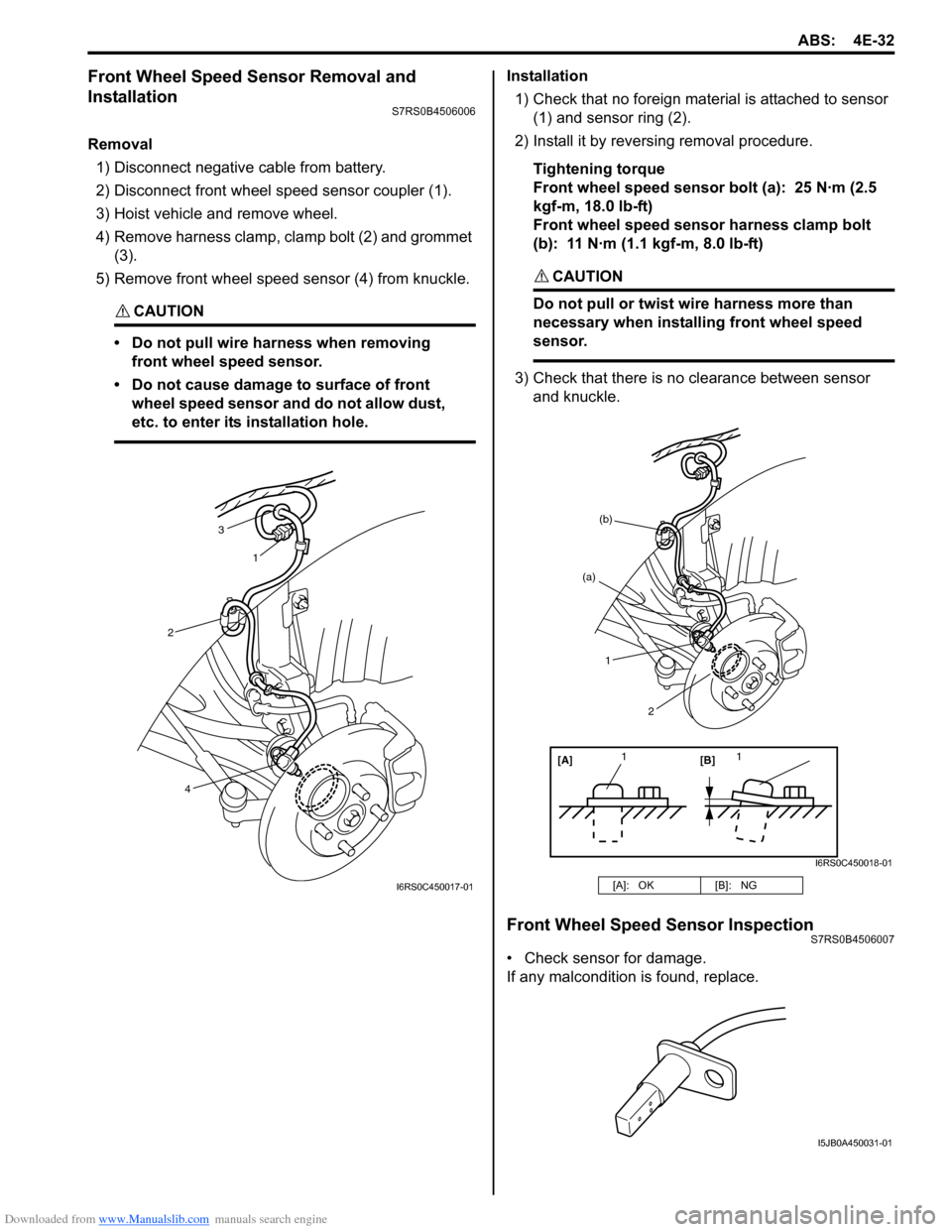
Removal1) Disconnect negative cable from battery.
2) Disconnect front wheel speed sensor coupler (1).
3) Hoist vehicle and remove wheel.
4) Remove harness clamp, clamp bolt (2) and grommet (3).
5) Remove front wheel speed sensor (4) from knuckle.
CAUTION!
• Do not pull wire ha rness when removing
front wheel speed sensor.
• Do not cause damage to surface of front wheel speed sensor and do not allow dust,
etc. to enter its installation hole.
Installation
1) Check that no foreign material is attached to sensor (1) and sensor ring (2).
2) Install it by reversing removal procedure.
Tightening torque
Front wheel speed sensor bolt (a): 25 N·m (2.5
kgf-m, 18.0 lb-ft)
Front wheel speed sensor harness clamp bolt
(b): 11 N·m (1.1 kgf-m, 8.0 lb-ft)
CAUTION!
Do not pull or twist wire harness more than
necessary when installing front wheel speed
sensor.
3) Check that there is no clearance between sensor
and knuckle.
Front Wheel Speed Sensor InspectionS7RS0B4506007
• Check sensor for damage.
If any malcondition is found, replace.
3
1
2
4
I6RS0C450017-01[A]: OK [B]: NG
[A][B]
11
(a)
(b)
1
2
I6RS0C450018-01
I5JB0A450031-01