2006 SUZUKI SWIFT Ground point
[x] Cancel search: Ground pointPage 22 of 1496
Downloaded from www.Manualslib.com manuals search engine 0A-1 General Information:
General Information
General Information
General Description
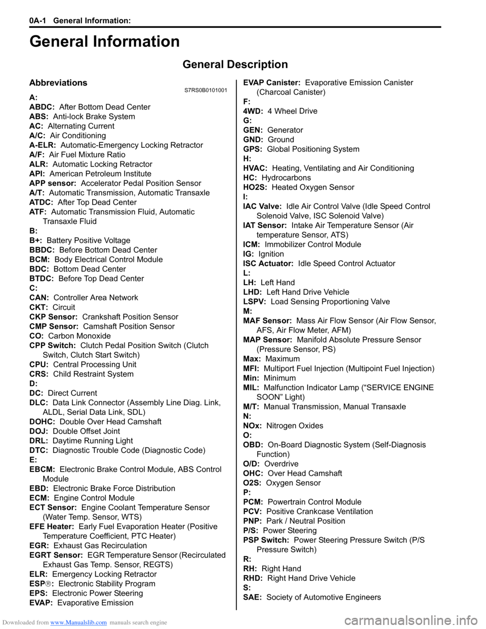
AbbreviationsS7RS0B0101001
A:
ABDC: After Bottom Dead Center
ABS: Anti-lock Brake System
AC: Alternating Current
A/C: Air Conditioning
A-ELR: Automatic-Emergency Locking Retractor
A/F: Air Fuel Mixture Ratio
ALR: Automatic Locking Retractor
API: American Petroleum Institute
APP sensor: Accelerator Pedal Position Sensor
A/T: Automatic Transmission , Automatic Transaxle
AT D C : After Top Dead Center
ATF: Automatic Transmission Fluid, Automatic
Transaxle Fluid
B:
B+: Battery Positive Voltage
BBDC: Before Bottom Dead Center
BCM: Body Electrical Control Module
BDC: Bottom Dead Center
BTDC: Before Top Dead Center
C:
CAN: Controller Area Network
CKT: Circuit
CKP Sensor: Crankshaft Position Sensor
CMP Sensor: Camshaft Position Sensor
CO: Carbon Monoxide
CPP Switch: Clutch Pedal Position Switch (Clutch
Switch, Clutch Start Switch)
CPU: Central Processing Unit
CRS: Child Restraint System
D:
DC: Direct Current
DLC: Data Link Connector (Assembly Line Diag. Link,
ALDL, Serial Data Link, SDL)
DOHC: Double Over Head Camshaft
DOJ: Double Offset Joint
DRL: Daytime Running Light
DTC: Diagnostic Trouble Code (Diagnostic Code)
E:
EBCM: Electronic Brake Cont rol Module, ABS Control
Module
EBD: Electronic Brake Force Distribution
ECM: Engine Control Module
ECT Sensor: Engine Coolant Temperature Sensor (Water Temp. Sensor, WTS)
EFE Heater: Early Fuel Evaporation Heater (Positive
Temperature Coefficient, PTC Heater)
EGR: Exhaust Gas Recirculation
EGRT Sensor: EGR Temperature Sensor (Recirculated
Exhaust Gas Temp. Sensor, REGTS)
ELR: Emergency Locking Retractor
ESP ®: Electronic Stability Program
EPS: Electronic Power Steering
EVAP: Evaporative Emission EVAP Canister:
Evaporative Emission Canister
(Charcoal Canister)
F:
4WD: 4 Wheel
Drive
G:
GEN: Generator
GND: Ground
GPS: Global Positioning System
H:
HVAC: Heating, Ventilating and Air Conditioning
HC: Hydrocarbons
HO2S: Heated Oxygen Sensor
I:
IAC Valve: Idle Air Control Valve (Idle Speed Control
Solenoid Valve, ISC Solenoid Valve)
IAT Sensor: Intake Air Temperature Sensor (Air
temperature Sensor, ATS)
ICM: Immobilizer Control Module
IG: Ignition
ISC Actuator: Idle Speed Control Actuator
L:
LH: Left Hand
LHD: Left Hand Drive Vehicle
LSPV: Load Sensing Proportioning Valve
M:
MAF Sensor: Mass Air Flow Sensor (Air Flow Sensor, AFS, Air Flow Meter, AFM)
MAP Sensor: Manifold Absolute Pressure Sensor
(Pressure Sensor, PS)
Max: Maximum
MFI: Multiport Fuel Injection (Mu ltipoint Fuel Injection)
Min: Minimum
MIL: Malfunction Indicator Lamp (“SERVICE ENGINE
SOON” Light)
M/T: Manual Transmission, Manual Transaxle
N:
NOx: Nitrogen Oxides
O:
OBD: On-Board Diagnostic System (Self-Diagnosis
Function)
O/D: Overdrive
OHC: Over Head Camshaft
O2S: Oxygen Sensor
P:
PCM: Powertrain Control Module
PCV: Positive Crankcase Ventilation
PNP: Park / Neutral Position
P/S: Power Steering
PSP Switch: Power Steering Pressure Switch (P/S
Pressure Switch)
R:
RH: Right Hand
RHD: Right Hand Drive Vehicle
S:
SAE: Society of Automotive Engineers
Page 26 of 1496

Downloaded from www.Manualslib.com manuals search engine 0A-5 General Information:
Vehicle Lifting PointsS7RS0B0101005
WARNING!
• Before applying hoist to underbody, always take vehicle balance throughout service into
consideration. Vehicle balance on hoist may change depending on what part to be removed.
• Before lifting up the vehicle, check to be sure that end of hoist arm is not in contact with brake pipe,
fuel pipe, bracket or any other part.
• When using frame contact hoist, apply hoist as shown (right and left at the same position). Lift up
the vehicle till 4 tires are a little off the ground and make sure that the vehicle will not fall off by
trying to move vehicle body in both ways. Work can be started only after this confirmation.
• Make absolutely sure to lock hoist after vehicle is hoisted up.
When Using Frame Contact Hoist
1
:2
:3
4
4
I4RS0A010001-01
1. Vehicle front
3. Floor jack position
2. Support position for frame contact hoist and safety stand 4. Body mounting stay
Page 40 of 1496
Downloaded from www.Manualslib.com manuals search engine 0B-10 Maintenance and Lubrication:
Steering System InspectionS7RS0B0206024
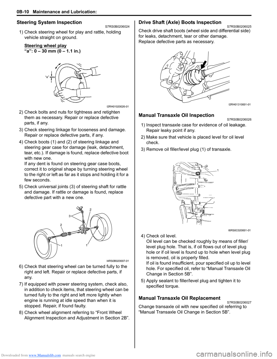
1) Check steering wheel for play and rattle, holding vehicle straight on ground.
Steering wheel play
“a”: 0 – 30 mm (0 – 1.1 in.)
2) Check bolts and nuts for tightness and retighten them as necessary. Repair or replace defective
parts, if any.
3) Check steering linkage for looseness and damage. Repair or replace defective parts, if any.
4) Check boots (1) and (2) of steering linkage and steering gear case for damage (leak, detachment,
tear, etc.). If damage is fo und, replace defective boot
with new one.
If any dent is found on steering gear case boots,
correct it to original shape by turning steering wheel
to the right or left as far as it stops and holding it for a
few seconds.
5) Check universal joints (3) of steering shaft for rattle and damage. If rattle or damage is found, replace
defective part with a new one.
6) Check that steering wheel can be turned fully to the
right and left. Repair or replace defective parts, if
any.
7) If equipped with power steering system, check also, in addition to check items, that steering wheel can be
turned fully to the right and left more lightly when
engine is running at idle speed than when it is
stopped. Repair, if found faulty.
8) Check wheel alignment referring to “Front Wheel Alignment Inspection and Adjustment in Section 2B”.
Drive Shaft (Axle) Boots InspectionS7RS0B0206025
Check drive shaft boots (wheel side and differential side)
for leaks, detachment, tear or other damage.
Replace defective parts as necessary.
Manual Transaxle Oil InspectionS7RS0B0206026
1) Inspect transaxle case for evidence of oil leakage. Repair leaky point if any.
2) Make sure that vehicle is placed level for oil level
check.
3) Remove oil filler/leve l plug (1) of transaxle.
4) Check oil level. Oil level can be checked roughly by means of filler/
level plug hole. That is, if oil flows out of level plug
hole or if oil level is found up to hole when level plug
is removed, oil is properly filled.
If oil is found insufficient, po ur specified oil up to level
hole. For specified oil, refe r to “Manual Transaxle Oil
Change in Section 5B”.
5) Apply sealant to filler/leve l plug and tighten it to
specified torque.
Manual Transaxle Oil ReplacementS7RS0B0206027
Change transaxle oil with new specified oil referring to
“Manual Transaxle Oil Change in Section 5B”.
I2RH01020026-01
2
3
2
1
1
I4RS0B020007-01
I2RH01310001-01
I6RS0C020001-01
Page 245 of 1496
Downloaded from www.Manualslib.com manuals search engine Engine General Information and Diagnosis: 1A-195
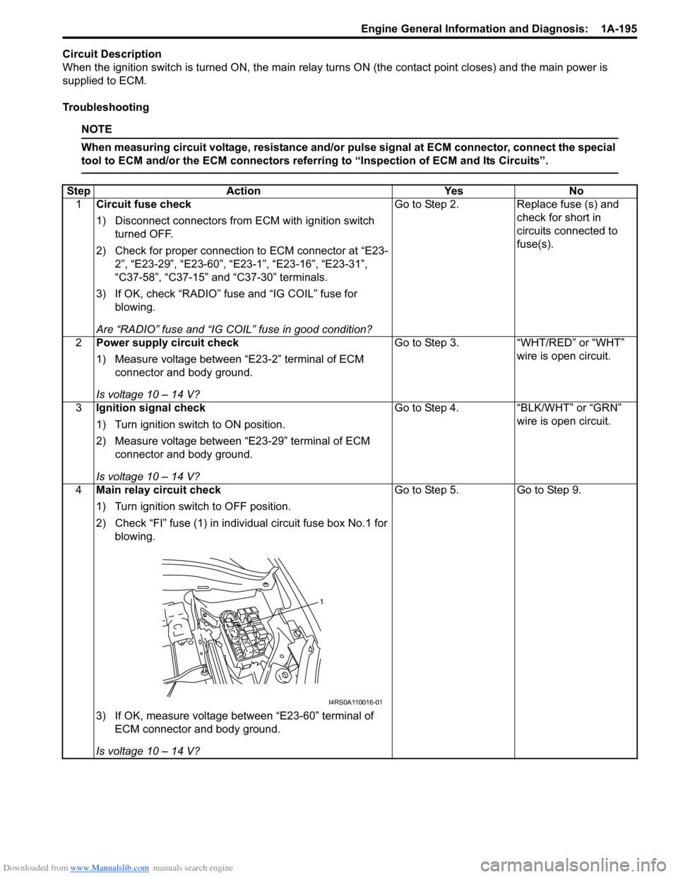
Circuit Description
When the ignition switch is turned ON, the main relay turns ON (the contact point closes) and the main power is
supplied to ECM.
Troubleshooting
NOTE
When measuring circuit voltage, resistance and/or pulse signal at ECM connector, connect the special
tool to ECM and/or the ECM connectors referri ng to “Inspection of ECM and Its Circuits”.
StepAction YesNo
1 Circuit fuse check
1) Disconnect connectors from ECM with ignition switch
turned OFF.
2) Check for proper connection to ECM connector at “E23- 2”, “E23-29”, “E23-60”, “E23-1”, “E23-16”, “E23-31”,
“C37-58”, “C37-15” and “C37-30” terminals.
3) If OK, check “RADIO” fuse and “IG COIL” fuse for blowing.
Are “RADIO” fuse and “IG COIL” fuse in good condition? Go to Step 2.
Replace fuse (s) and
check for short in
circuits connected to
fuse(s).
2 Power supply circuit check
1) Measure voltage between “E23-2” terminal of ECM
connector and body ground.
Is voltage 10 – 14 V? Go to Step 3.
“WHT/RED” or “WHT”
wire is open circuit.
3 Ignition signal check
1) Turn ignition switch to ON position.
2) Measure voltage between “E23-29” terminal of ECM
connector and body ground.
Is voltage 10 – 14 V? Go to Step 4.
“BLK/WHT” or “GRN”
wire is open circuit.
4 Main relay circuit check
1) Turn ignition switch to OFF position.
2) Check “FI” fuse (1) in indivi dual circuit fuse box No.1 for
blowing.
3) If OK, measure voltage between “E23-60” terminal of ECM connector and body ground.
Is voltage 10 – 14 V? Go to Step 5.
Go to Step 9.
1
I4RS0A110016-01
Page 403 of 1496
Downloaded from www.Manualslib.com manuals search engine Starting System: 1I-2
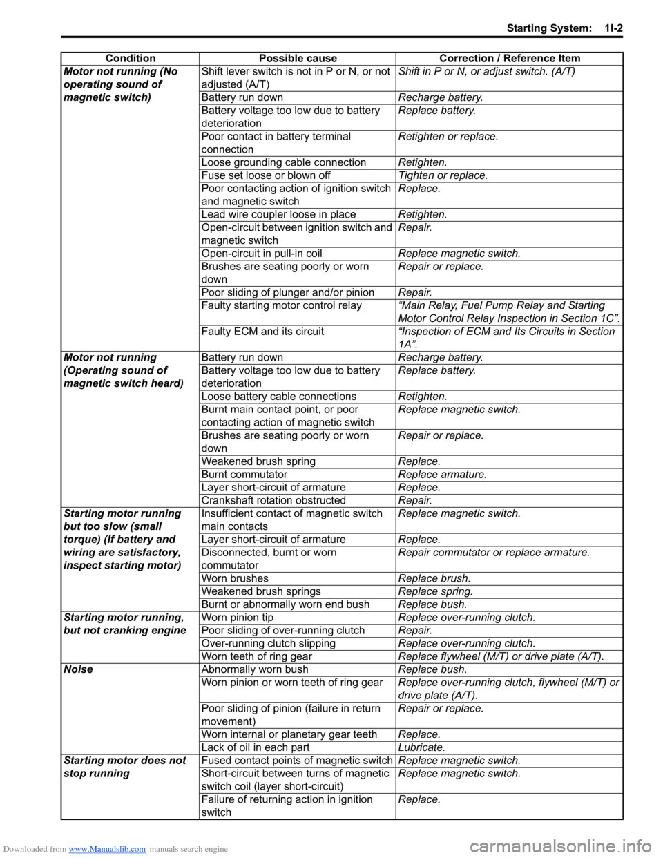
ConditionPossible cause Correction / Reference Item
Motor not running (No
operating sound of
magnetic switch) Shift lever switch is not in P or N, or not
adjusted (A/T)
Shift in P or N, or
adjust switch. (A/T)
Battery run down Recharge battery.
Battery voltage too low due to battery
deterioration Replace battery.
Poor contact in battery terminal
connection Retighten or replace.
Loose grounding cable connection Retighten.
Fuse set loose or blown off Tighten or replace.
Poor contacting action of ignition switch
and magnetic switch Replace.
Lead wire coupler loose in place Retighten.
Open-circuit between ignition switch and
magnetic switch Repair.
Open-circuit in pull-in coil Replace magnetic switch.
Brushes are seating poorly or worn
down Repair or replace.
Poor sliding of plunger and/or pinion Repair.
Faulty starting motor control relay “Main Relay, Fuel Pump Relay and Starting
Motor Control Relay Inspection in Section 1C”.
Faulty ECM and its circuit “Inspection of ECM and Its Circuits in Section
1A”.
Motor not running
(Operating sound of
magnetic switch heard) Battery run down
Recharge battery.
Battery voltage too low due to battery
deterioration Replace battery.
Loose battery cable connections Retighten.
Burnt main contact point, or poor
contacting action of magnetic switch Replace magnetic switch.
Brushes are seating poorly or worn
down Repair or replace.
Weakened brush spring Replace.
Burnt commutator Replace armature.
Layer short-circuit of armature Replace.
Crankshaft rotation obstructed Repair.
Starting motor running
but too slow (small
torque) (If battery and
wiring are satisfactory,
inspect starting motor) Insufficient contact
of magnetic switch
main contacts Replace magnetic switch.
Layer short-circuit of armature Replace.
Disconnected, burnt or worn
commutator Repair commutator or replace armature.
Worn brushes Replace brush.
Weakened brush springs Replace spring.
Burnt or abnormally worn end bush Replace bush.
Starting motor running,
but not cranking engine Worn pinion tip
Replace over-running clutch.
Poor sliding of over-running clutch Repair.
Over-running clutch slipping Replace over-running clutch.
Worn teeth of ring gear Replace flywheel (M/T) or drive plate (A/T).
Noise Abnormally worn bush Replace bush.
Worn pinion or worn teeth of ring gear Replace over-running clutch, flywheel (M/T) or
drive plate (A/T).
Poor sliding of pinion (failure in return
movement) Repair or replace.
Worn internal or planetary gear teeth Replace.
Lack of oil in each part Lubricate.
Starting motor does not
stop running Fused contact points of magnetic switch
Replace magnetic switch.
Short-circuit between turns of magnetic
switch coil (layer short-circuit) Replace magnetic switch.
Failure of returning action in ignition
switch Replace.
Page 408 of 1496
Downloaded from www.Manualslib.com manuals search engine 1I-7 Starting System:
Spring
Inspect brush springs for wear, damage or other
abnormal conditions. Replace if necessary.
Brush spring tension
Standard: 2.2 kg (4.85 lb)
Limit: 0.6 kg (1.33 lb)
Brush Holder
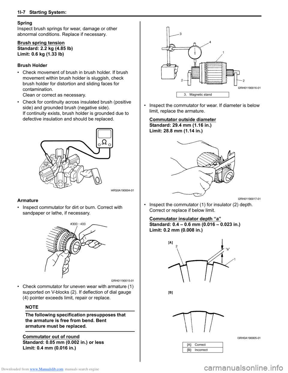
• Check movement of brush in brush holder. If brush movement within brush holder is sluggish, check
brush holder for distortion and sliding faces for
contamination.
Clean or correct as necessary.
• Check for continuity across insulated brush (positive side) and grounded brush (negative side).
If continuity exists, brus h holder is grounded due to
defective insulation and should be replaced.
Armature
• Inspect commutator for dirt or burn. Correct with sandpaper or lathe, if necessary.
• Check commutator for uneven wear with armature (1) supported on V-blocks (2). If deflection of dial gauge
(4) pointer exceeds limit, repair or replace.
NOTE
The following specification presupposes that
the armature is free from bend. Bent
armature must be replaced.
Commutator out of round
Standard: 0.05 mm (0.002 in.) or less
Limit: 0.4 mm (0.016 in.) • Inspect the commutator for wear. If diameter is below
limit, replace the armature.
Commutator outside diameter
Standard: 29.4 mm (1.16 in.)
Limit: 28.8 mm (1.14 in.)
• Inspect the commutator (1) for insulator (2) depth. Correct or replace if below limit.
Commutator insulator depth “a”
Standard: 0.4 – 0.6 mm (0.016 – 0.023 in.)
Limit: 0.2 mm (0.008 in.)
I4RS0A190004-01
I2RH01190015-01
3. Magnetic stand
[A]: Correct
[B]: Incorrect
I2RH01190016-01
I2RH01190017-01
I3RH0A190005-01
Page 409 of 1496

Downloaded from www.Manualslib.com manuals search engine Starting System: 1I-8
• Check the commutator and armature core. If there is
continuity, the armature is grounded and must be
replaced.
• Check for continuity between segments. If there is no continuity at any test point , there is an open circuit
and the armature must be replaced.
Gears
Inspect the internal gear and the planetary gears for
wear, damage or other abnorma l conditions. Replace if
necessary. Pinion and Over-Running Clutch
• Inspect the pinion for wear, damage or other abnormal
conditions.
Check that clutch locks up when turned in direction of
drive and rotates smoothly in reverse direction.
Replace if necessary.
• Inspect the spline teeth for wear or damage. Replace if necessary.
Inspect the pinion for smooth movement.
Front Housing Bush
Inspect the bush for wear or damage. Replace if
necessary.
I2RH01190019-01
I2RH01190020-01
I2RH01190021-01
I2RH01190022-01
I2RH01190023-01
I2RH01190024-01
Page 558 of 1496
Downloaded from www.Manualslib.com manuals search engine 4E-19 ABS:
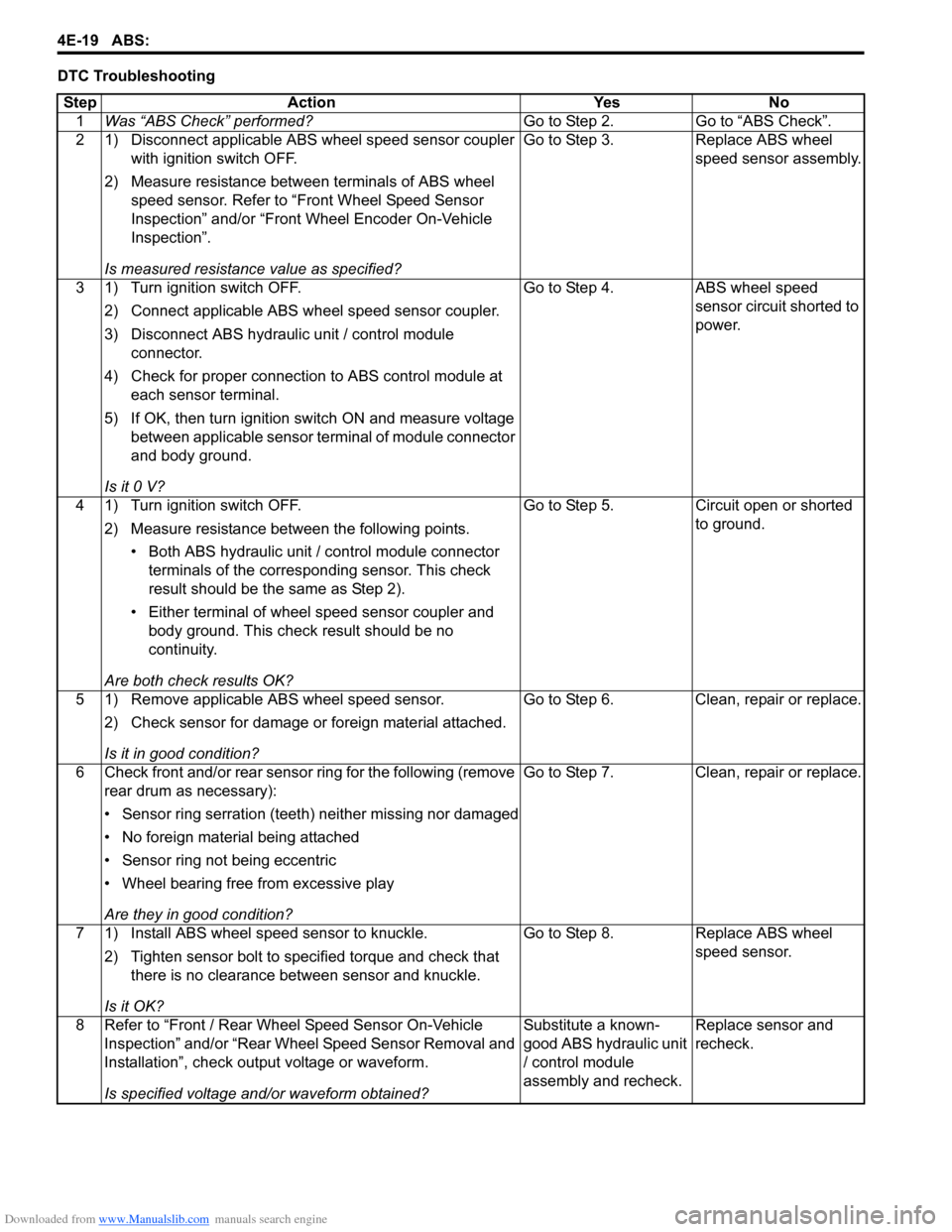
DTC TroubleshootingStep Action Yes No 1 Was “ABS Check” performed? Go to Step 2. Go to “ABS Check”.
2 1) Disconnect applicable ABS wheel speed sensor coupler with ignition switch OFF.
2) Measure resistance betw een terminals of ABS wheel
speed sensor. Refer to “Front Wheel Speed Sensor
Inspection” and/or “Front Wheel Encoder On-Vehicle
Inspection”.
Is measured resistance value as specified? Go to Step 3. Replace ABS wheel
speed sensor assembly.
3 1) Turn ignition switch OFF. 2) Connect applicable ABS wh eel speed sensor coupler.
3) Disconnect ABS hydraulic unit / control module connector.
4) Check for proper connection to ABS control module at each sensor terminal.
5) If OK, then turn ignition switch ON and measure voltage between applicable sensor terminal of module connector
and body ground.
Is it 0 V? Go to Step 4. ABS wheel speed
sensor circuit shorted to
power.
4 1) Turn ignition switch OFF. 2) Measure resistance between the following points.• Both ABS hydraulic unit / control module connector terminals of the correspo nding sensor. This check
result should be the same as Step 2).
• Either terminal of wheel speed sensor coupler and body ground. This check result should be no
continuity.
Are both check results OK? Go to Step 5. Circuit open or shorted
to ground.
5 1) Remove applicable ABS wheel speed sensor. 2) Check sensor for damage or foreign material attached.
Is it in good condition? Go to Step 6. Clean, repair or replace.
6 Check front and/or rear sensor ring for the following (remove rear drum as necessary):
• Sensor ring serration (teeth) neither missing nor damaged
• No foreign material being attached
• Sensor ring not being eccentric
• Wheel bearing free from excessive play
Are they in good condition? Go to Step 7. Clean, repair or replace.
7 1) Install ABS wheel speed sensor to knuckle. 2) Tighten sensor bolt to specified torque and check that there is no clearance between sensor and knuckle.
Is it OK? Go to Step 8. Replace ABS wheel
speed sensor.
8 Refer to “Front / Rear Wheel Speed Sensor On-Vehicle Inspection” and/or “Rear Wheel Speed Sensor Removal and
Installation”, check output voltage or waveform.
Is specified voltage and/or waveform obtained? Substitute a known-
good ABS hydraulic unit
/ control module
assembly and recheck.
Replace sensor and
recheck.