Page 387 of 1496

Downloaded from www.Manualslib.com manuals search engine Fuel System: 1G-12
Fuel Tank Inlet Valve InspectionS7RS0B1706012
WARNING!
Before starting the following procedure, be
sure to observe “Precautions on Fuel System
Service” in order to reduce the risk or fire
and personal injury.
Check fuel tank inlet valve for the following.
If any damage or malfunction is found, replace.
•Damage
• Smooth opening and closing
Fuel Tank Removal and InstallationS7RS0B1706013
WARNING!
Before starting the following procedure, be
sure to observe “Precautions on Fuel System
Service” in order to reduce the risk or fire
and personal injury.
Removal1) Relieve fuel pressure in fuel feed line according to
“Fuel Pressure Relief Procedure”.
2) Disconnect negative cable at battery.
3) Hoist vehicle.
4) Remove exhaust center pipe.
5) Disconnect fuel filler hose and breather hose from
filler neck referring to “Fue l Tank Inlet Valve Removal
and Installation”.
6) Due to absence of fuel tank drain plug, drain fuel tank by pumping fuel out through fuel tank filler.
Use hand operated pump device to drain fuel tank.
CAUTION!
• Do not force pump hose into fuel tank, or pump hose may damage fuel tank inlet
valve.
• Never store fuel in an open container due to possibility of fire or explosion.
7) Disconnect fuel pipe joint and fuel hoses (1) from fuel pipes (2) referring to “Fuel Hose Disconnecting
and Reconnecting”.
8) Support fuel tank (1) with jack (2) and remove its mounting bolts.
9) Lower fuel tank a little as to disconnect wire harness at connector (1) and ground wire (2), then remove
fuel tank.
I2RH0B170019-01
12
I4RS0A170008-01
12
I4RS0A170009-01
1
2
I6RS0C170005-02
Page 388 of 1496

Downloaded from www.Manualslib.com manuals search engine 1G-13 Fuel System:
Installation
CAUTION!
• When connecting joint, clean outside surfaces of pipe where joint is to be
inserted, push joint into pipe till joint lock
clicks and check to ensure that pipes are
connected securely, or fuel leak may
occur.
• Never let the fuel hoses touch the ABS sensor harness (if equipped).
1) If parts have been removed from fuel tank, install them before installing fuel tank to vehicle.
2) Raise fuel tank (1) with jack (2) and connect fuel pump connector (3), ground wire (4) and clamp wire
harness.
Tightening torque
Ground wire bolt (a): 11 N·m (1.1 kgf-m, 8.0 lb-ft)
3) Install fuel tank to vehicle. Tightening torque
Fuel tank bolt (b): 45 N·m (4.5 kgf-m, 33.0 lb-ft) 4) Connect fuel filler hose (1
) and breather hose (2) to
filler neck (3) as shown in figure, and clamp them
securely.
Tightening torque
Fuel filler hose clamp (a): 2 N·m (0.2 kgf-m, 1.5
lb-ft)
5) Connect fuel feed hose (1) and vapor hose (2) to each pipe as shown in figure, and clamp them
securely.
6) Install exhaust center pipe referring to “Exhaust Pipe and Muffler Removal and Installation in Section 1K”.
7) Connect negative cable at battery.
8) With engine OFF, turn ignition switch to ON position and check for fuel leaks.
Fuel Tank InspectionS7RS0B1706014
After removing fuel tank, check hoses and pipes
connected to fuel tank for leaks, loose connections,
deterioration or damage. Also check fuel pump
assembly gaskets for leaks, visually inspect fuel tank for
leaks and damage.
Replace any damaged or malconditioned parts.
(b)(b)
1
2
3
4
(a)
I6RS0C170006-02
1
2
(a)
3
I4RS0A170012-01
1
2
I4RS0A170013-01
Page 392 of 1496

Downloaded from www.Manualslib.com manuals search engine 1G-17 Fuel System:
Special Tools and Equipment
Special ToolS7RS0B1708001
09912–5761009912–58421
Injector checking tool plate Checking tool set
�) This kit includes the
following items. 1. Tool body
and washer, 2. Body plug, 3.
Body attachment-1, 4.
Holder, 5. Return hose and
clamp, 6. Body attachment-2
and washer, 7. Hose
attachment-1, 8. Hose
attachment-2�)
09912–58432 09912–58442
Fuel pressure gauge hose Fuel pressure gauge
This tool is included in fuel
pressure gauge set (09912-
58413). �) This tool is included in fuel
pressure gauge set (09912-
58413).
�)
09912–58490 09919–47020
3-way joint & hose Quick joint remover
�)�)
09930–88530 SUZUKI scan tool
Injector test lead —
�) This kit includes following
items. 1. Tech 2, 2. PCMCIA
card, 3. DLC cable, 4. SAE
16/19 adapter, 5. Cigarette
cable, 6. DLC loop back
adapter, 7. Battery power
cable, 8. RS232 cable, 9.
RS232 adapter, 10. RS232
loop back connector, 11.
Storage case, 12.�)
Page 394 of 1496

Downloaded from www.Manualslib.com manuals search engine 1H-2 Ignition System:
Schematic and Routing Diagram
Ignition System Wiring Circuit DiagramS7RS0B1802001
E23-60
E23-29 12V 5V
5V
E23-1
E23-16
BLK/WHT
BLK/RED
BLK/RED BLK/RED
BLK/YELBLK/YEL
BLK/YEL
GRN
BLKWHT
WHT
BRN/WHT
BLK/ORN
BLK
BLK
C37-20
BLK/RED
PNK
5V
C37-21
BLK/WHT
7
3 4
1
12 5
6
2
11
8
9
10
GRN/YEL
GRN/WHT
C37-6
C37-5 5V
5V
RED/YEL
C37-58
C37-15
C37-30
E23
C37
34
1819
567
1011
17
20
47 46
495051
2122
52 16
25 9
24
14
29
55
57 54 53
59
60 58 2
262728
15
30
56 4832 31
34353637
40
42 39 38
44
45 43 41 331
1213
238
34
1819
567
1011
17
20
47 46
495051
2122
52 16
25 9
24
14
29
55
57 54 53
59
60 58 2
262728
15
30
56 4832 31
34353637
40
42 39 38
44
45 43 41 331
1213
238
13
14
15
16
17
50A50A80A
BLK/ORN
E23-31 BLK
I4RS0B180001-01
1. Ignition switch 7. No.1 spark plug 13. Individual circuit fuse box
No.1
2. Main relay 8. No.2 spark plug 14. “IG ACC” fuse
3. Ignition coil assembly for No.1 and No.4 spark plugs 9. No.3 spark plug 15. “FI” fuse
4. Ignition coil assembly for No.2 and No.3 spark plugs 10. No.4 spark plug 16. Junction block assembly
5. CMP sensor 11. Sensed information (MAP sensor, ECT sensor, MAF and IAT
sensor, TP sensor, Knock sensor, VSS, Electric load signal,
Engine start signal) 17. “IG COIL” fuse
6. CKP sensor 12. Battery fuse box
Page 395 of 1496
Downloaded from www.Manualslib.com manuals search engine Ignition System: 1H-3
Component Location
Ignition System Components LocationS7RS0B1803001
NOTE
The figure shows left-hand steering vehicle. For right-hand steering vehicle, parts with (*) are installed
at the opposite side.
16*
1
2
14
7
5 12 11
410
6
89
3 13*
15
17
I6RS0C180001-01
1. ECM 7. ECT sensor13. Data link connector
2. Ignition coil assembly for No.1 and No.4 spark plugs 8. MAF and IAT sensor 14. Battery fuse box
3. Ignition coil assembly for No.2 and No.3 spark plugs 9. Electric throttle body 15. Relay box
4. CMP sensor 10. Wheel speed sensor (VSS) 16. Junction block assembly
5. CKP sensor 11. High-tension cords
6. MAP sensor 12. Knock sensor
Page 400 of 1496

Downloaded from www.Manualslib.com manuals search engine 1H-8 Ignition System:
Ignition Coil Assembly (Including ignitor)
Removal and Installation
S7RS0B1806005
Removal1) Disconnect negative (–) cable at battery.
2) Remove air cleaner assembly with air intake pipe and cylinder head upper cover.
3) Disconnect ignition coil coupler.
4) Disconnect high-tension cord (3) from ignition coil assembly (2).
5) Remove ignition coil bolts (1) and then pull out ignition coil assembly.
Installation 1) Install ignition coil assembly (2).
2) Tighten ignition coil bolts (1) to specified torque, and then connect igni tion coil coupler.
Tightening torque
Ignition coil bolt (a): 10 N·m (1.0 kgf-m, 7.5 lb-ft)
3) Install high-tension cord (3) to ignition coil assembly while gripping its cap.
4) Install cylinder head upper cover and air cleaner assembly with air intake pipe.
5) Connect negative (–) cable to battery.
Ignition Coil Assembly (Including ignitor)
Inspection
S7RS0B1806006
Measure secondary coil for resistance.
If resistance is out of specification, replace ignition coil
assembly.
Secondary coil resistance
7.5 – 10.3 k Ω at 20 °C, 68 ° F
Ignition Timing InspectionS7RS0B1806007
NOTE
• Ignition timing is not adjustable. If ignition
timing is out of specification, check
system related parts.
• Before starting engine, place transmission gear shift lever in “Neutral” (shift selector
lever to “P” range for A/T model), and set
parking brake.
1) Connect scan tool to DLC (1) with ignition switch OFF.
Special tool
(A): SUZUKI scan tool
2) Start engine and warm it up to normal operating temperature.
3) Make sure that all of electrical loads except ignition are switched off.
4) Check to be sure that idle speed is within specification referring to “Idle Speed and IAC
Throttle Valve Opening Inspection in Section 1A”
5) Fix ignition timing by using “Fixed Spark” of “Misc Test” mode on scan tool.
I2RH0B180006-01
I3RM0A180004-01
I2RH0B180007-01
(A)
1
I4RS0B180003-01
Page 401 of 1496

Downloaded from www.Manualslib.com manuals search engine Ignition System: 1H-9
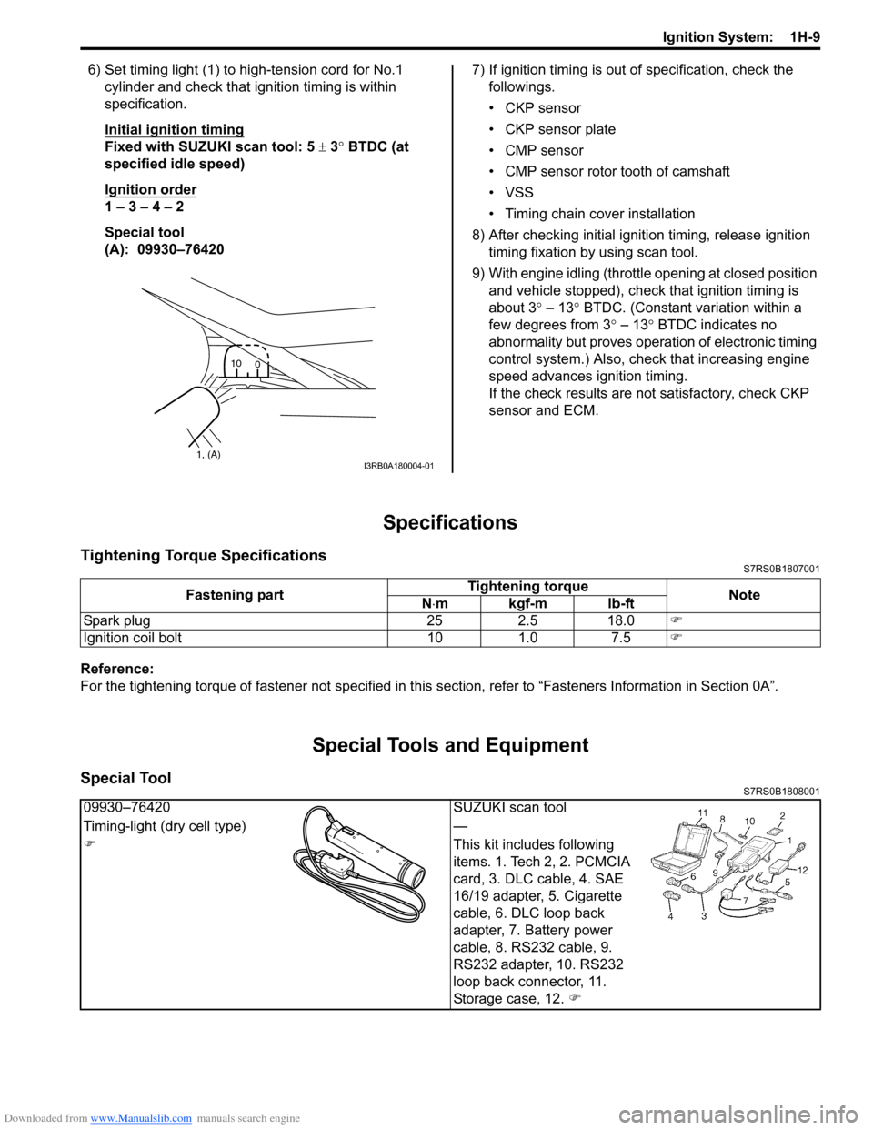
6) Set timing light (1) to high-tension cord for No.1 cylinder and check that ignition timing is within
specification.
Initial ignition timing
Fixed with SUZUKI scan tool: 5 ± 3° BTDC (at
specified idle speed)
Ignition order
1 – 3 – 4 – 2
Special tool
(A): 09930–76420 7) If ignition timing is out
of specification, check the
followings.
• CKP sensor
• CKP sensor plate
• CMP sensor
• CMP sensor rotor tooth of camshaft
• VSS
• Timing chain cover installation
8) After checking initial igniti on timing, release ignition
timing fixation by using scan tool.
9) With engine idling (throttl e opening at closed position
and vehicle stopped), check that ignition timing is
about 3 ° – 13° BTDC. (Constant variation within a
few degrees from 3 ° – 13° BTDC indicates no
abnormality but proves operation of electronic timing
control system.) Also, check that increasing engine
speed advances ignition timing.
If the check results are not satisfactory, check CKP
sensor and ECM.
Specifications
Tightening Torque SpecificationsS7RS0B1807001
Reference:
For the tightening torque of fastener not specified in this section, refer to “Fasteners Information in Section 0A”.
Special Tools and Equipment
Special ToolS7RS0B1808001
1, (A)10
0I3RB0A180004-01
Fastening part Tightening torque
Note
N ⋅mkgf-mlb-ft
Spark plug 25 2.5 18.0 �)
Ignition coil bolt 10 1.0 7.5 �)
09930–76420SUZUKI scan tool
Timing-light (dry cell type) —
�) This kit includes following
items. 1. Tech 2, 2. PCMCIA
card, 3. DLC cable, 4. SAE
16/19 adapter, 5. Cigarette
cable, 6. DLC loop back
adapter, 7. Battery power
cable, 8. RS232 cable, 9.
RS232 adapter, 10. RS232
loop back connector, 11.
Storage case, 12. �)
Page 402 of 1496

Downloaded from www.Manualslib.com manuals search engine 1I-1 Starting System:
Engine
Starting System
Schematic and Routing Diagram
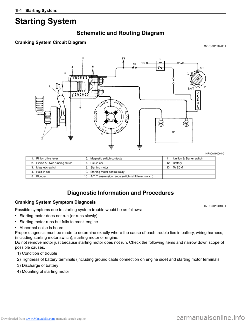
Cranking System Circuit DiagramS7RS0B1902001
Diagnostic Information and Procedures
Cranking System Symptom DiagnosisS7RS0B1904001
Possible symptoms due to starting system trouble would be as follows:
• Starting motor does not run (or runs slowly)
• Starting motor runs but fails to crank engine
• Abnormal noise is heard
Proper diagnosis must be made to determine exactly where the cause of each trouble lies in battery, wiring harness,
(including starting motor switch), starting motor or engine.
Do not remove motor just because starting motor does not run. Check the following items and narrow down scope of
possible causes.
1) Condition of trouble
2) Tightness of battery terminals (including ground cable connection on engine side) and starting motor terminals
3) Discharge of battery
4) Mounting of starting motor
I4RS0A190001-01
1. Pinion drive lever 6. Magnetic switch contacts 11. Ignition & Starter switch
2. Pinion & Over-running clutch 7. Pull-in coil 12. Battery
3. Magnetic switch 8. Starting motor 13. To ECM
4. Hold-in coil 9. Starting motor control relay
5. Plunger 10. A/T: Transmission range switch (shift lever switch)